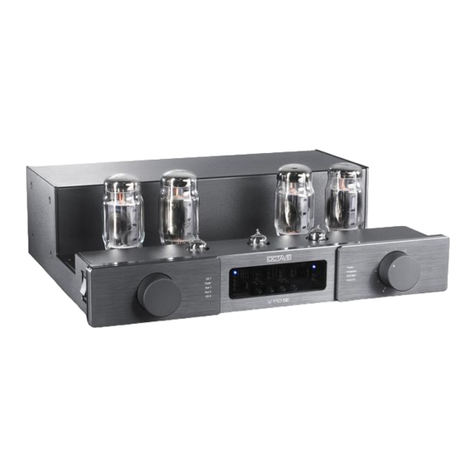
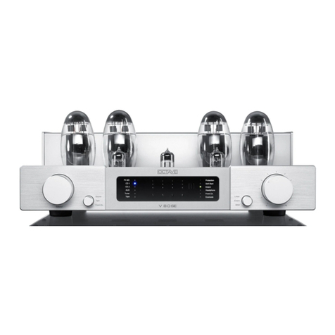
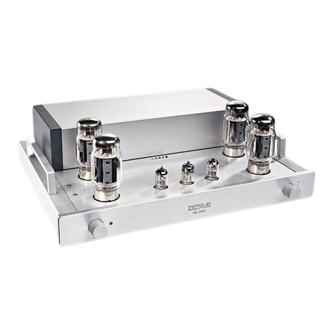
Octave V 50 MKII User manual

OWNER'S MANUAL
V
50 MKII

INTRODUCTION
Congratulations - and thank you for choosing OCTAVE!
V 50 MKII
You are about to enjoy the benefits of one of the world's most innovative and reliable amplifiers.
Look after it, and it will provide you many years of listening pleasure.
You will often hear people insist that tube amplifier design has not progressed for years. The
operating principles of tubes have been documented extensively and are well known to amplifier
designers. The same can, of course, be said for transistor amplifiers.
Nevertheless, there is still room for further development with both of these technologies. This is
both necessary and desirable. With tube amplifiers in particular, a general reluctance to depart
from the classic circuit designs has not done the technology any favours. Today's loudspeakers
and source equipment provide better performance than ever before, but also make greater
demands on amplifiers. Modern sound reproduction equipment delivers a level of performance at
a price that simply would not have been possible 20, or even 10, years ago.
These advances have been achieved through the application of cutting edge technology as it
becomes available and affordable.
Integrating these technologies into amplifier design demands a detailed knowledge of the inner
workings of amplifiers and an appreciation of the sonic ramifications of each modification.
We have specialized in tube amplification for the past 20 years, during which time we have
developed a number of innovative technologies that have made us one of the leaders in the field.
We hope you will enjoy many hours of wonderful music with your OCTAVE amplifier.
Andreas Hofmann
1

2

Contents
Page
Introduction
1. Description of the V 50 MKII......................................................... 4
2. Safety instructions ....................................................................... 5
2.1. Before you begin........................................................................... 5
2.2. Placement..................................................................................... 6
2.3. Warranty ....................................................................................... 6
3. Setting up...................................................................................... 7
4. Operation - The V 50 MKII front panel ......................................... 8
5. The connections - V 50 MKII rear panel ...................................... 9
6. Tubes
6.1. Removing the cover ..................................................................... 10
6.2. Tube layout .................................................................................. 10
6.3. Tube service life............................................................................ 11
6.4. Replacing tubes ........................................................................... 11
7. Phono MM/MC Option.................................................................. 12
7.1. The role of the phono amplifier..................................................... 12
7.2. Guidelines for connecting to the phono section ........................... 12
8. Option: External Black Box........................................................... 13
9. IR remote control ......................................................................... 15
10. Troubleshooting............................................................................ 16
11. Technical data .............................................................................. 17
12. Frequently Asked Questions......................................................... 18
3

1. DESCRIPTION OF THE V 50 MKII
A novelty in our range of products is the integrated amplifier V 50. Compact, highly efficient and
equipped with all features, it represents the minimum demand according to our philosophy of
sound reproduction.
Without our 15 years of experience in the field of preamplifiers as well as power amplifiers, it
would not have been possible to develop such a component. For example, a completely new
technology of power supplies and power transformers had to be developed to enable us, to put a
sensitive phono MM/MC input in such a powerful neighbourhoood. The bias of the amplifier
V 50 is regulated electronically and thereby secures a long lasting high-quality performance
and makes the V 50 very easy to handle. This kind of regulation - with the above described ad-
vantages - can nowadays not be found elsewhere.
The power amplifier delivers 2 x 50 Watt (basic version with 4 x EL 34) in AB-mode and is able to
drive even difficult loudspeakers. The auto-bias makes it possible to use the following tubes:
KT88, 6550 A, 6 L 6, 5881 (6 CA 7).
Construction of the V 50
The signal flow inside the OCTAVE V 50 is designed that noise or hum due to electromagnetic
interference is ruled out and the signal path is as short as possible.
The magnetic shielding inside the housing also suppresses feedback from the transformer to the
sensitive input stages.
OUTPUT INPUTS
Input
stages
Output stage
Output
transformers
Mains
transformer
Power supply
electronics
Magnetic
shielding
Signal flow
4

2. SAFETY INSTRUCTIONS
2.1. Before you begin
Before using your V 50 MK2, please remove the protective cover and install the output tubes
supplied with your amplifier in the appropriate sockets (see Removing the Cover and Tube Lay-
out). Replace the cover before switching on.
Operating the amplifier without its protective cover is dangerous and not recommended.
In case of emergency: disconnect the plug from the mains supply
Never use an amplifier that is damaged or faulty. Make sure that it cannot be used until it has
been repaired by a qualified service engineer.
Make sure that there is easy access to the IEC socket and power cord.
Do not open the case
There are dangerously high voltages and hot tubes inside this equipment. To avoid a burn or the
risk of electric shock, never allow anyone except qualified personnel to open the case or remove
the cover.
Servicing and maintenance
For reasons of safety, please ensure that servicing, repairs and other modifications to OCTAVE
equipment are carried out only by a qualified technician. Fuses should also only be changed by a
qualified technician. Always replace fuses with ones of the same type and rating. If your amplifier
requires servicing, please ship or take your equipment directly to OCTAVE or to one of our au-
thorized service centres.
Explanation of the warning symbols:
The exclamation point within an equilateral triangle is intended to alert
the user to important operating and maintenance instructions.
The lightning flash with arrowhead symbol within an equilateral triangle is
intended to alert the user to the presence of uninsulated 'dangerous volt-
ages' within the product's enclosure that may be sufficient to constitute a
risk of electric shock to persons.
Before connecting
Make sure that the voltage of your amplifier matches your electricity supply voltage.
Grounding
This amplifier is a protection class 1 device (with an earth conductor). To exclude the risk of elec-
tric shock in the event of a fault, the unit must be grounded. Use a three-core mains cable with a
three-pin plug (supplied).
Safety warning: hot tubes!
Warning: Remove the protective cover at your own risk. OCTAVE accepts no responsibility for
injuries caused by the removal of this cover.
5
2. SAFETY INSTRUCTIONS
2.2. Placement
1. Location
OCTAVE equipment is designed strictly for use in a dry domestic environment. Do not use it in
the open air or in damp environments!
Never place plants or liquid filled containers on your OCTAVE equipment. Take care that objects
do not fall or liquids are not spilled into the enclosure. Should this happen, remove the mains plug
immediately and have your amplifier checked by a qualified service technician.
Condensation may form if the amplifier is taken from a cold environment into a warm one. If you
do this, wait until the amplifier has reached room temperature and is dry before switching it on.
Avoid installing the unit close to sources of heat such as radiators or anywhere that it may be in
direct sunlight.
Do not operate the unit near flammable materials, gases or vapours. Avoid areas where there
may be heavy accumulations of dust or where the unit may be subject to mechanical vibration.
Place your OCTAVE amplifier on a stable, even surface.
2. Cover
Never operate the amplifier without the protective cover.
3. Ventilation
Make sure that your amplifier has a good flow of air around it. If you intend to install your equip-
ment in a cupboard or a shelf unit, ensure that there is at least a ten centimetre gap between the
ventilation slots and the walls all around the amplifier. The rear panel of cupboards should have
ventilation holes to prevent heat build up. Do not rest the equipment on a soft surface such as
carpet or foam sheeting.
2.3. Warranty
OCTAVE can only guarantee the safety, reliability and performance of this unit if modifications
and repairs are carried out by specialized personnel and if the amplifier is operated in accor-
dance with the instructions contained in this manual.
6

3. SETTING UP
1. In your own interest, please observe the safety precautions and positioning advice contained
in Chapter 2.
2. Before setting up your OCTAVE amplifier, switch off all the other equipment that you intend to
connect to it. This will avoid problems that may arise when you plug this equipment in.
3. Connect the cables from your signal sources such as CD player, tuner, etc. to the appropriate
inputs on the amplifier. When connecting recording devices, be careful to connect the re-
cording and replay inputs and outputs correctly.
4. Connect your loudspeakers to your OCTAVE amplifier, making sure that you observe the cor-
rect polarity (positive on the amplifier to positive on the speakers).
5. Check that the amplifier is switched off before connecting the power cable to the wall socket.
Before connecting the optional, outboard Black Box, ensure that it is switched off. (see Chap-
ter 8, Black Box)
6. Now switch the amplifier on using the power (on/off) switch (see Chapter 4, Operation)
After switch-on, the ‘Wait’ LED will illuminate in addition to the normal power LED. The ampli-
fier is ready for use as soon as this LED goes out.
7. Check that the volume control is not set at maximum before playing music through
the amplifier.
8. Switch the other components on in any order.
7

4. OPERATION
The V 50 MKII front panel
Main Power Switch
c
d
e
f
g
LED ON The amplifier is ready to operate
LED OFF This LED burns, if the electronic-overload-protection is activated. It
turns off the power amplifier in case of overmodulation, short circuit
of the loudspeaker outputs and tube damages. To start the amplifier
again, you have to switch it off by the main power switch. After the
elimination of the cause it has to be switched on again.
Input Selector
The selected input is shown by the LED-chain:
IN1 Line amplifier input
With a phono-board the IN 1 is the MC input
IN2 Second line amplifier input
With a phono-board the IN 2 is the MM input
CD Playback CD
TUNER Playback Tuner or DSR
TAPE Playback Tape or DAT
STAND BY The stand-by-mode reduces the bias of the tubes to 10%. This op-
erational mode has to be kept for approximately 2 hours to burn in
new tubes
Metal-Cover Is used to cool the tubes and also to offer a view on the tubes
Volume Control
IR-Sensor For the optional usage of the remote control the infrared receiver is
located below the volume knob behind the cover. Therefore, this part
of the front panel should not be covered by anything.
8

5. CONNECTIONS
V 50 MKII rear panel
L
R
L
R
TAPETUNERCD
PLAYREC
MMMC
IN 2IN 1
PHONO
GROUND POWER RATING
230 V /50 Hz/550 VA
++
SPEAKER OUT
4 - 16 Ohm
RL
BLACK-BOX
ANSCHLUSS
ACHTUNG!
Black-Box nur bei
ausgeschaltetem
Gerät abtrennen
bzw. anschließen
THE INTEGRATED TUBE AMP
MODELL
SERIEN-NR.:
made in Germany
:
PHONO GROUND Ground connection for the turntable
c
d
e
f
g
h
i
j
CD CD input
TUNER Tuner or DSR input
TAPE REC Recording output for tape or DAT
TAPE PLAY Playback input for tape or DAT
IN 1 Line amplifier input
With a phono-board IN 1 is the MC-input
IN 2 Second line amplifier input
With a phono-board IN 2 is the MM-input
BLACK-BOX SOCKET The black-box is an external boost of the power supply
for the power amplifier. By using the black-box a higher
impulse power as well as a better dynamic behaviour
can
be achieved.
Caution! Before connecting or disconnecting the black-
box, the system has to be switched off by the mains
switch.
SPEAKER OUT Loudspeaker terminals
POWER CONNECTION AC input, IEC socket
9

6. TUBES
6.1. REMOVING THE COVER
1. For your own safety, switch the amplifier off and disconnect the mains power cord.
2. Release the 12 M4 socket head bolts of the cover.
3. Pull the cover upward.
6.2. TUBE LAYOUT
11
9
3
5
6
7
1
2
4
8
phono board
line board
arranged over
power supply
board (standing)
power amplifier
board
10
Tubes used also available under this description:
power tubes:
c+ dEL 34 left channel (6 CA 7)
e+ fEL 34 right channel (6 CA 7)
driver tubes
gECC 83 (E 83 CC / ECC 803 S /12 AX 7 A / 12 AX 7 WA)
h- lECC 82 - selected (E 82 CC / ECC 802 S / 12 AU 7 / 5814 A)
ECC 81 (E 81 CC / ECC 801 S / 12 AT 7 / 12 AT 7 WA)
(only used with version phono MM/MC)
10

6. TUBES
6.3. Tube service life
6.4. Replacing tubes
Thanks to the protection circuits and soft start electronics, the output tubes used in you
r
amplifier should achieve an average service life of 5 years.
The driver tubes can last for 10 years or more.
Because the tubes have different service lives, you will never have to renew the entire tube
complement at the same time.
Please note that some tubes need a long time (up to 300 hours) to achieve their optimum
sound quality.
Driver tubes
Replacement driver tubes require no adjustment.
Output tubes:
General procedure:
1. Switch-off the V 50, disconnect the AC mains plug and let the V 50 cool for 10
minutes.
2. Take off the top by unscrewing the fastening screws at the sides, on top and on
the rear.
3. Pull-off old tubes
Pull the tubes off the sockets with extremely care, without jamming the connec-
tions.
4. Put-in new tubes
When putting in new tubes, make sure, that all connection pins are straight-
faced. If this should not be the case, straighten the pins carefully by hand.
5. Cleaning information
It is not advisable to use cleanser and other substances to clean the tube-
sockets. Clean dirty sockets with compressed air and clean dirty contact pins at
tubes carefully with a wire brush.
6. General information
No adjustment works are necessary, when new tubes are installed. It may take
long to burn them in (up to approx. 300 hours), until they reach their sound po-
tential. It is possible, that the tubes may not prove faulty until approx. 100 hours
of use. Therefore, it is necessary to be especially careful when using untested
tubes. However, faulty or wrong tubes do usually not lead to defects in the inte-
grated tube amplifier.
11

7. PHONO MM/MC OPTION
7.1. The role of the phono
A record player is an electro-mechanical device. Music signals are "pressed" into the grooves
in the record, and these are physically tracked and read by the pickup cartridge. In order to
get the entire 20 Hz - 20 KHz frequency range into the grooves, the frequency response has
to be shaped by lowering the level of the low frequency information and raising the level of the
high frequency information. This predefined equalization curve is known as RIAA equalization.
A phono amplifier must exactly equalize for RIAA recording characteristic if it is to avoid col-
ouring the sound. Equalization accuracy must be within 0.5 dB over the entire frequency
range, with channel matching of at least 0.1 dB.
7.2. Guidelines for connecting to the phono section
1. Turn the function switch oon the front of the V 50 to the input IN 1 or IN 2, depending on
whether you want to connect a MM- or a MC-system.
IN 1 position MC: for real MC-systems, which have an output voltage <1 mV
IN 2 position MM: for moving-magnet-systems and MC-high-output-systems
2. Connect the cinch-circuits of the drive to the corresponding input IN 1 or IN 2 on the rear
panel of the V 50.
3. Connect the ground cable of the drive to the ground connection GND nof the V 50 according
to the operating instructions of the pick-up arm/cable producer (the ground cable is usually a
black wire with FCA-cinch-plugs)
ÎDepending on the pick-up arm-cable-wiring, there may be no additional ground
connection, as it may already be connected internally
ÎEspecially with MM-systems in connection with metal-pick-up-arms you have to
check, whether a ground connection is necessary or not
Explanation
Usually, the ground connection is connected to the pick-up arm or the head shell. This is nec-
essary to prevent hum-disturbances or broadcasting interferences. Therefore, in most cases
the ground connection is useful in order to stop these interferences.
However, some producers of MM-systems still connect the pick-up arm output with the chas-
sis, which means, they connect the pick-up arm with the conducting surface. This leads to
hum-disturbances caused by the double grounding of the ground cable. In this case, you have
to disconnect the carried ground cable. (Usually this is only the case with MM-systems)
12

8. OPTION: EXTERNAL BLACK BOX
What exactly is the Black Box?
The Black Box is a power supply upgrade. Its circuit incorporates additional reservoir capacitors
to improve power supply current delivery, counteract fluctuations in the supply voltage, and sup-
press low frequency mains supply 'noise'.
What does it do?
The sophisticated circuitry of the Black Box will always produce an improvement in sound quality.
The sound becomes more relaxed without losing pace; the subtle timbres of individual instru-
ments become more defined, and the soundstage gains more depth. The improved stabilization
of the power supply increases the amplifier's burst output capability, making loudspeaker effi-
ciency less critical. It also enables the amplifier to handle speakers with minimum impedances as
low as 2 ohms.
The outboard Black Box option is not available in all countries.
Black-Box
Indicator LED Hi
g
h-current plu
g
The LED lights up continuously when the power amplifier is on.
The LED goes out when the protection circuitry trips. This is normal, as the protection circuitry
cuts the power to the amplifier.
13

8. OPTION: EXTERNAL BLACK BOX
Specifications:
Capacity: Low-inductance, low ESR, high power electrolytics with
100 A current capacity (impulse current)
Dimensions: Width x height x depth = 170 x 97 x 257 mm
Weight: 3.1 kg
Connecting to the amplifier
Warning!! Before connecting the Black Box, switch the unit off using the power
switch and wait for 1 minute.
When inserting the connector, guide the anti-rotation lug carefully into the mat-
ing recess in the socket.
When you switch the amplifier on, the LED on the front panel of the Black Box
will illuminate.
Please note:
When the amplifier's electronic protection circuitry cuts in, this will cause the
LED on the Black Box to go out, as it interrupts the power to the amplifier.
Should you wish to disconnect the Black Box, switch the amplifier off first and
wait until the LED on the Black Box goes out before doing so.
14

9. IR REMOTE CONTROL
For volume
c
Front panel screws (Two M3 Philips countersunk screws)
d
Keypad
e
Battery compartment for two AA 1.5 V batteries
f
Volume button + button: louder; - button: quieter
g
Infrared transmitter
Point the transmitter at the amplifier. The remote will operate up to a distance of about 8
metres. (Please remember that infrared cannot penetrate solid objects. Make sure there is
a clear line of sight between the transmitter and the receiver).
CHANGING THE BATTERIES
1. Undo both of the M3 countersunk screws on the remote control keypad using a no. 1
Philips screwdriver.
2. Insert a small screwdriver in the slot at the side of the remote and ease the keypad up.
3. Take the battery compartment out of the unit and replace the batteries. Observe the
battery polarity markings.
4. Check the operation of the remote by pressing one of the buttons. Reassemble the unit.
15

10. TROUBLESHOOTING
Hum and crackling
Hum in an audio system is often caused by several system components being earthed indi-
vidually. It is particularly common with tuners, VCRs or satellite receivers where the earthed
aerial cables can cause a hum loop via the aerial input.
Tube power amplifiers are normally earthed, and the V 50 is no exception. However, remov-
ing the earth wire on your mains plugs is not a solution, You can isolate the aerial earth con-
nection with a special signal isolator. This device has no adverse affect on the sound or pic-
ture quality of tuners or TVs.
Check also that the phono plugs are a tight fit. Bend the outer earth contact inwards slightly
if necessary. Sometimes the internal pin in a phono plug may not be a tight enough fit, in
which case you should change either the interconnect cable or the socket.
Switching interference
Older fridges and 12 V halogen lamps can cause cracking through the loudspeakers when
they switch on and off.
Solution: The only solution is to use a single power socket board for your entire system and
to use a different power outlet in your listening room. However, it is not always
possible to eliminate the problem entirely.
Channels are not balanced
1
.
Damaged cables and poorly fitting phono plugs can create resistance in the signal path
enough to reduce the output level of one channel.
Solution: Try new cables or clean the plugs and sockets with isopropyl alcohol.
2.
A
tape or DAT machine connected to the REC Out may have a faulty Record input (o
r
faulty interconnect cable) causing the signal to overload. This can result in an imbal-
ance between the left and right channels.
Solution: Disconnect the tape/DAT machine
3. A faulty output tube can cause a drop in output in one channel and generate distortion
at higher output levels.
Solution: Locate the defective tube using the bias adjustment facility. Replace the
tube.
Increased hiss on one channel
An irregular hissing sound is a sign of a worn driver tube.
Solution: Replace the worn tube.
16

11. TECHNICAL DATA
Features
1. Electronic protection- and controlling-system: The V 50 is equipped with a current at make-
limitation. This protects the tubes against peak loads that occur, when the V 50 is turned on.
Heating and operating voltage are adjusted slowly to operating standards. The life of the tubes
is thereby prolonged tremendously. At the same time, the electronic protection controls the
power amplifier. In case of overmodulation, short circuit of the loudspeaker outputs or tube
damages, the power amplifier is turned-off. The loudspeakers and the electronic of the power
amplifier are therefore fail-safe.
2. Stand-by function of the power amplifier to bridge middle periods of not being used (max. 5
hours). Also important to burn in new tubes
3. Auto-bias electronic: The electronic adjusts automatically to the tubes used. Tolerances of the
tubes, due to age or supply fluctuations, are fully stabilized. This makes it possible to use vir-
tually every tube available on the market, without having to adjust it.
4. A newly developed 600 VA-power-transformer
5. New developed, completely low-noise phono and line stages
6. By connecting the optional black box as an external boost of the power supply, the power and
the dynamic of the power amplifier can be increased once again.
7. The front panel is mill-cutted of massive aluminium and can be produced on demand in spe-
cial anodised colours.
Technical data
Power amplifier section:
power output: 2 x 50 Watt, 4 Ohms
frequency response: 10 Hz - 50 kHz / 0 - 3 dB
distortion factor: <0,1 % with 5 Watt, 8 Ohms
signal to noise ratio: >90 dB
attenuation factor: 8
minimal load impedance: 2 Ohms
Phono section:
sensibility MC: 0,1 mV
input resistance 100 Ohms
sensibility MM 4 mV
input resistance MM 47 kOhms II 150 pF
General data:
power consumption: 100 Watt no-load operation, 250 Watt full modulation
50 Watt in stand-by mode
dimensions: 380x170x440 mm (width x height x depth)
weight: 23 kg
remote control for the volume infrared transmitter with 2 x 1,5 V, size AA
Notice: The information contained in the manual is subject to change without notice
17

12. Frequently Asked Questions
1. Can you operate the V 50 MK2 when no loudspeakers are connected?
Yes. The V 50 MK2, like all OCTAVE amplifiers, is fully protected against open circuit opera-
tion, i.e. the amplifier will come to no harm if it is operated without loudspeakers connected.
2. How do you recognize a faulty tube?
There are 3 different symptoms indicating a faulty tube:
1. Broken heater filament. The tube stops glowing
2. Defective cathode layer. The tube glows, but no current can flow.
3. Internal short circuit. Normally, the electronic protection cuts in and the red Off LED illu-
minates.
With faults 1 and 2, the amplifier will still operate, although the channel containing the faulty
tube will be quieter than normal. At low listening levels, the fault may not be obvious, but dis-
tortion will become evident at higher listening levels.
If fault 3 occurs, the protection circuits will normally switch the amplifier off. You may also
hear loud background noises just before it switches off, although these are not harmful to the
amplifier.
3. Is there a loss of sound quality as tubes age?
No. Tubes normally sound the same throughout their service life and our soft-start technol-
ogy contributes greatly to extending the service life of tubes. You can tell when an outpu
t
tube has reached the end of its useful life: it becomes impossible to adjust it correctly. Drive
r
tubes cannot be checked, but these will generally last for well over 10 years.
4. Does the V 50 MK2 have to have all tubes fitted?
In principle, the V 50 MK2 will also operate without tubes. It is sometimes useful to do this
when testing the operation of the switching functions such as the selector switch, remote
control, etc. Of course, it is not possible to play music under these circumstances.
For test purposes, a channel may also be used with a single output tube, although its powe
r
output will, of course, be reduced. The amplifier will come to no harm if it is operated con-
tinuously like this.
Operation without driver tubes is also possible for test purposes, although, for obvious rea-
sons, music playback is not possible.
5. What is the significance of loudspeaker impedance and efficiency?
The impedance and efficiency of modern loudspeakers is not an issue for OCTAVE amplifi-
ers. The often-quoted damping factor is not normally a guarantee that an amplifier will exer
t
tight control over the loudspeakers. In practice, speakers with a sensitivity of 85 dB and
higher are suitable for use with tube amplifiers. The high stability of the OCTAVE power am-
plifier technology even allows you to connect speakers that dip as low as 2 ohms.
18

OCTAVE Audio
Andreas Hofmann
Industriestr. 13
D - 76307 Karlsbad
T
Table of contents
Other Octave Amplifier manuals

Octave
Octave HP 300 MK2 User manual

Octave
Octave Black Box User manual

Octave
Octave JUBILEE Mono User manual

Octave
Octave V 70 Class A User manual

Octave
Octave HP 300 SE User manual

Octave
Octave HP 700 User manual

Octave
Octave V70 User manual

Octave
Octave Super Black Box User manual

Octave
Octave HP500MK3 User manual

Octave
Octave Phono EQ.2 User manual

Octave
Octave JUBILEE MONO SE User manual

Octave
Octave Phono Module User manual

Octave
Octave RE 280 MK2 User manual

Octave
Octave V 16 Single Ended User manual

Octave
Octave V 80 SE User manual

Octave
Octave V 110 SE User manual

Octave
Octave v70se User manual

Octave
Octave JUBILEE 300 B User manual

Octave
Octave JUBILEE Pre User manual

Octave
Octave RE 320 User manual