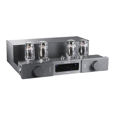
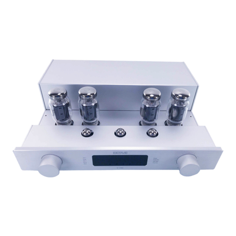
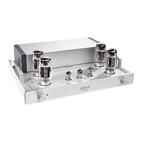
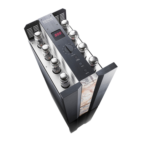
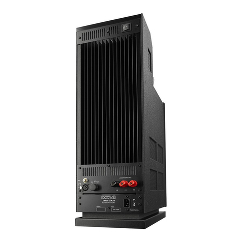
Octave JUBILEE Mono User manual

JUBILEE Mono

1
FOREWORD
I wish to personally thank you for choosing
OCTAVE products and congratulate you on
your purchase of your new
Jubilee mono power amplifier.
Here at our head office in Karlsbad, right on
the edge of the Black Forest, we have been
designing and building high quality, long-
lasting hi-fi equipment for over 20 years
that will – quite literally – provide you with
hours of musical pleasure for many years to
come.
Today's loudspeakers and high-resolution
source equipment continue to be very
demanding of amplifiers. As a result, achiev-
ing improved amplifier sound quality re-
quires greater levels of technical innovation
than ever before.
OCTAVE specializes in the ongoing devel-
opment of upgradeable circuit designs and
has earned a reputation over recent years
as a world leader in the field of high-end
tube amplifier design. Thanks to our years of
experience and our in-depth understanding
of amplifier technologies and their side ef-
fects, OCTAVE is able to achieve a musical
quality and degree of reliability that seemed
impossible or unaffordable only a few years
ago
I trust that you will enjoy many hours of wonderful music with your
OCTAVE amplifier.
Andreas Hofmann
Chief Designer and Owner of OCTAVE Audio

3
CONTENTS
Page
Foreword
1. Introduction .......................................................................................... 4
1.1. What makes OCTAVE amplifiers special............................................. 4
1.2. JUBILEE MONO product description ................................................... 5
2. Safety instructions................................................................................ 6
2.1. Before you begin .................................................................................. 6
2.2. Placement............................................................................................. 7
2.3. Bevore powering up.............................................................................. 7
3. Operating components ........................................................................ 8
3.1. JUBILEE MONO rear panel.................................................................. 8
3.2. JUBILEE MONO top control panel....................................................... 10
4. Getting started...................................................................................... 12
4.1. Unpack and check the contents ........................................................... 12
4.2. Removing the grille............................................................................... 12
4.3. Installing the power tubes .................................................................... 13
4.4. Recommended procedure.................................................................... 14
5. Bias measurement facility..................................................................... 16
5.1. How the bias works .............................................................................. 17
5.2. How to set the bias............................................................................... 17
6. The electronic protection system.......................................................... 18
6.1. How the protection system works......................................................... 18
6.2. Identifying defective tubes.................................................................... 18
7. Tubes.................................................................................................... 19
7.1. Tube layout .......................................................................................... 19
7.2. General procedure for changing tubes................................................. 20
7.3. Tube service life.................................................................................... 20
7.4. Removing the protective assembly to change tubes............................ 21
7.4.1. Removing the protective grille to change output tubes ........................ 21
7.4.2. Removing the side panel to replace driver tubes................................. 22
8. Troubleshooting.................................................................................... 23
9. Technical data and dimensions............................................................ 24
10. Technical data, diagrams ..................................................................... 25
11. FAQ ..................................................................................................... 27

4
1. INTRODUCTION
1.1 What makes OCTAVE amplifiers special
Technology
Tubes themselves do not themselves guaran-
tee high quality sound. Only by partnering them
with innovative electronics designed to create
the optimum conditions for the tubes you can
achieve consistently high sound quality.
OCTAVE amplifiers are equipped with a power
management system whose design is unique.
This electronic monitoring and protection sys-
tem is comprised of a soft-start control and a
protection system. An electronic control module
regulates and controls all the functions of our
amplifiers. When you switch it on, the soft start
circuit ensures that the tube heaters and oper-
ating voltages are ramped up gently. If a fault
should occur, the protection system steps in to
switch the power off virtually instantaneously.
This intelligent power management system
guarantees total protection against all conceiv-
able faults.
An optimized power supply, sophisticated
power supply circuitry and the high load stability
of the output stages ensure that every power
amp and integrated amp bearing the OCTAVE
name is capable of developing its full sonic
qualities with virtually any loudspeaker.
Together, these measures deliver a supremely
consistent sound quality and a dependability
that is recognized as world class.
Manufacturing
Every OCTAVE amplifier is 100 percent
"made in Germany". Our products are built
individually by hand and thoroughly tested
before they leave the factory. We design and
make our own custom transformers. We
maintain extremely high quality standards
through close cooperation with specialist
suppliers and by insisting on producing me-
chanical components in house on the latest
CNC machines. The most important contrib-
uting factor, however, is the highly qualified
and enthusiastic team working here at OC-
TAVE. The company owner, Andreas Hof-
mann, retains ultimately responsibility for the
design and development of all OCTAVE
products.
Sound
OCTAVE is fully convinced of the musicality
and sonic superiority of tubes. But our ex-
perience tells us that using tubes does not
automatically lead to audiophile sound qual-
ity. We appreciate that the sound character-
istics of an amplifier are a result of the inter-
action of its component parts. This means
that a high degree of technical skill must be
applied to optimizing every detail in order to
design a reliable amplifier that will maintain
its characteristics over time and that will
convince the critical listener over the long
term that its reproduction of music is both
honest and natural

5
1. INTRODUCTION
1.2 JUBILEE MONO product description
The JUBILEE MONO monoblocs are push-pull
power amplifiers in pentode configuration. The
power amplifiers produce approx. 280W at 2%
THD.
OCTAVE power amplifiers have always set
new standards.
Andreas Hofmann's RE 280 stereo power am-
plifier left traditional power amp technologies
far behind when it was first introduced. It goes
without saying that this amplifier - like all OC-
TAVE products since - was equipped with OC-
TAVE's proprietary Power Management and
Protection electronics
POWER MANAGEMENT
The Power Management system monitors and
controls the heating and supply voltages at
switch-on. This is tremendously important in
extending the service life of the tubes and
maintaining a consistent sound. It also relieves
the power supply components of the strain of
handling huge surge currents at turn-on.
PROTECTION SYSTEM
Many manufacturers neglect to include elec-
tronic or even passive protection systems in
their tube amps, which means that the life - and
indeed the operational safety - of these amplifi-
ers is greatly dependent on factors over which
the user has no control. OCTAVE fits its power
amplifiers with an electronic protection system
as a matter of course.
LOAD STABILITY
The technical breakthroughs that set the
original RE 280 apart were its optimized input
gain section and its power supply. Indeed, it
used a totally new power supply design,
featuring double star-earthing and supply
voltage isolation. The optimization of the input
stages provided absolute immunity from
influences such as the loudspeaker load,
together with excellent phase stability for highly
accurate push-pull operation and an extension
of the usable frequency range up to 80kHz.
From a sound quality point of view, these
enhancements delivered a consistent tonal
performance and independence from the
impedance response and efficiency level of the
speakers.
PENTODE DESIGN
With the JUBILEE MONO power amplifiers,
Andreas Hofmann has gone one step further.
While they have the same power management
and optimized input stage as other OCTAVE
power amps, they benefit from an innovative
and enhanced output stage configuration. What
is revolutionary about this new generation of
amplifiers is that we have employed the classic,
yet almost forgotten, pentode configuration.
The classic pentode configuration was quite
commonly used in earlier power amplifiers. It
offered the benefits of reliability and a relatively
high power output. From a modern perspective,
its disadvantage was reduced dynamic stability
and a high level of distortion. These effects are
not a direct result of the pentode itself, but
rather of the circuitry employed at the time.
Andreas Hofmann has now developed a new
design that eliminates the drawbacks of the
classic pentode configuration. This innovative
design involves the use of a second, separate
power supply circuit for the auxiliary current
needed for the pentode mode of operation. The
characteristics of this enhanced pentode circuit
are virtually ideal from both a sound quality and
an engineering point of view. Among the
welcome side effects of the enhanced pentode
circuit are absolute immunity against
interference and fluctuations in the supply
voltage, and an ability to accept compatible
output tubes.
BIAS
A further effective feature is the bias
measurement facility.
Unlike the simpler class-A power amplifier type,
AB amplifiers require adjustment of the negative
grid bias to optimize the idle current for the
power tubes. The setting can change as the
tubes age and it must also be adjusted
whenever tubes are replaced. Normally, this
requires test equipment and a knowledge of
what and where to measure, but with the
JUBILEE MONO, you can check and adjust the
bias any time the amp is on.
This adjustment has a huge influence on the
sound quality and performance characteristics
of an amplifier (see Bias diagram under
Technical data).
6
2. SAFETY INSTRUCTIONS
2.1. Before you begin
Please read this Owner's Manual before you
use the equipment for the first time.
Operating the amplifier without its protective
grille is dangerous and not recommended.
In case of emergency: disconnect the plug
from the mains supply.
Never use an amplifier that is damaged or
faulty. Make sure that it cannot be used until it
has been repaired by a qualified service
engineer.
Make sure that there is easy access to the IEC
socket and power cord.
Do not open the case
There are dangerously high voltages and hot
tubes inside this equipment. To avoid a burn or
the risk of electric shock, never allow anyone
except qualified personnel to open the case or
remove the grille.
Servicing and maintenance
For reasons of safety, please ensure that
servicing, repairs and other modifications to
OCTAVE equipment are carried out only by a
qualified technician. Fuses should be also be
changed only by a qualified technician. Always
replace fuses with ones of the same type and
rating. If your amplifier requires servicing,
please ship or take your equipment directly to
OCTAVE or to one of our authorized service
centres.
Explanation of the warning symbols:
The lightning flash with
arrowhead symbol within an
equilateral triangle is
intended to alert the user to
the presence of uninsulated
'dangerous voltages' within
the product's enclosure that
may be sufficient to
constitute a risk of electric
shock to persons.
The exclamation point within
an equilateral tri-angle is
intended to alert the user to
important operating and
mainte-nance instructions.
Before connecting up
Make sure that the voltage of your amplifier
matches your electricity supply voltage.
Grounding
This amplifier is a protection class 1 device
(with an earth conductor). To exclude the risk of
electric shock in the event of a fault, the unit
must be grounded. Use a three-core mains
cable with a three-pin plug (supplied).
Safety warning: Hot tubes!
Warning: Remove the protective grille at your
own risk. OCTAVE cannot accept any
responsibility for injuries caused by the removal
of this grille.
Warranty
OCTAVE can only guarantee the safety,
reliability and performance of this unit if
modifications and repairs are carried out by
specialized personnel and if the amplifier is
operated in accordance with the instructions
contained in this manual.

7
2. SAFETY INSTRUCTIONS
2.2. Placement
1. Location
OCTAVE equipment is designed strictly for use
in a dry domestic environment. Do not use it in
the open air or in damp environments!
Never place plants or liquid filled containers on
your OCTAVE equipment. Take care that
objects do not fall or liquids are not spilled into
the enclosure. Should this happen, remove the
mains plug immediately and have your
amplifier checked by a qualified service
technician.
Condensation may form if the amplifier is taken
from a cold environment into a warm one. If
you do this, wait until the amplifier has reached
room temperature and is dry before switching it
on.
Avoid installing the unit close to sources of heat
such as radiators or anywhere that it may be in
direct sunlight.
Do not operate the unit near flammable
materials, gases or vapours. Avoid areas
where there may be heavy accumulations of
dust or where the unit may be subject to
mechanical vibration.
Place your OCTAVE amplifier on a stable, even
surface.
2. Grille
Never operate the amplifier without the
protective grille.
3. Ventilation
Make sure that your amplifier has a good flow of
air around it. If you intend to install your
equipment in a cupboard or a shelf unit, ensure
that there is at least a ten-centimetre gap
between the ventilation slots and the walls all
around the amplifier. The rear panel of
cupboards should have ventilation holes to
prevent heat build up. Do not rest the equipment
on a soft surface such as carpet or foam
sheeting.
2.3. Before powering up
1. In your own interest, please observe the
Safety precautions and positioning advice
(Chapter 2)
2. Before connecting your OCTAVE amplifier
up, switch off all the other equipment that
you intend to connect to it. This will avoid a
source of possible problems when you plug
these components in.
3. Connect the outputs from your preamplifier
to the appropriate inputs on the JUBILEE
MONO.
4. Connect your loudspeakers to your
JUBILEE MONO amplifiers, making sure
that you observe the correct polarity
(positive on the amplifier to positive on the
speakers).
5. Check that the amplifier is switched off
before connecting the power cable to the
wall socket.
6. The power switch for the JUBILEE MONO is
located on the rear panel (see Chapter 3.1 -
Operation).
To fully disconnect the
amplifier from the mains,
you must unplug the power
cable from the wall socket.
Switching the amplifier off using the power
switch is not sufficient. Make sure that
access to the power switch is never
obstructed.
When you switch the amplifier on, the
measurement display and the appropriate
signal LEDs illuminate (see Chapt. 4 Setting
up).
The unit is ready for use after about three
minutes.
7. Check that the volume control is not set at
maximum before playing music through the
amplifier.
8. Switch the other components on in any
order.

8
3. OPERATING COMPONENTS
3.1. JUBILEE MONO rear panel
+
_
Cynch
Input
XLR
XLR
1 : GROUND
2 :
3 :
+
+
LED OUT
muting aktiv
Cynch
XLR
Netzeingang
Mains
230 V /50 Hz/2 kW
ٛ
Netzschalter
Mains Power
Output
Speaker 2 - 16 Ohm/250 W
limited edition
BIAS-Regler
When power preselection on max:
turn control until the measuring
instrument shows a value of 1000.
LED ON
input aktiv
Input
sensitivity:
2 V / 5 k
ٛ
Bei Leistungsvorwahl auf max:
Regler drehen, bis Messgerät
Wert 1.000 anzeigt.

9
3. OPERATING COMPONENTS
Power inlet
AC input, IEC socket
Power switch
The plug on the power cord should be
viewed as a disconnect device. For this
reason, please ensure that this plug is
easily accessible at all times.
Selector knobs and electronic switches
are not suitable for use as disconnect
devices.
Loudspeaker outputs
Loudspeaker terminals. When
connecting the power amplifier to your
speakers, take care to connect the red
terminal on your amplifier to the positive
terminal on your speakers. The blue
(negative) terminal connects to the
negative terminal on your speakers. The
outputs are connected in parallel and are
identical.
Input panel
The power amplifier is equipped with an
RCA phono and an XLR input. You can
select the appropriate input using the
input toggle switch. You can also
connect both inputs at the same time and
switch between them.
XLR pin connections:
1 = ground, 2 = +, 3 = -
The LED next to the switch illuminates
when the input is active
(see Muting facility on top control panel)
Model identification plate
Model and serial number
Bias adjustment
This control sets the bias for all eight
power tubes simultaneously. This is
done by setting a value of 1000 for one
of the eight tubes with the bias setting
active in the top control panel.
If the eight power tubes have been
properly selected, they should not
deviate more than 15 percent from each
other. The value displayed in the meter
will be between 850 and 1000.
(see also Chapters 4 and 5)
Cynch
Input
XLR
XLR
1 : GROUND
2 :
3 :
+
LED OUT
muting aktiv
Cynch
XLR
LED ON
input aktiv
Input
sensitivity:
2 V / 5 k
ٛ
+
BIAS-Regler
When power preselection on max:
turn control until the measuring
instrument shows a value of 1000.
Bei Leistungsvorwahl auf max:
Regler drehen, bis Messgerät
Wert 1.000 anzeigt.

10
3. OPERATING COMPONENTS
3.2. JUBILEE MONO top control panel

11
3. OPERATING COMPONENTS
On/Standby (Power) button
The button in the top control panel can
only be used to switch the amplifier on
when the power switch has been
turned on at the rear of the unit.
000 will appear in the display . During
the switch-on phase, the yellow A and
green B LEDs illuminate in the display
(see Chapt. 4).
Muting button
This button disables the inputs on the
power amplifier. The green LED B lights
up in the display and the LED next to
the input selector switch (input) goes
out.
You can now connect RCA phono or
XLR leads without having to switch the
amplifier off.
Bias button
This button reduces the bias current to a
third of its nominal value.
The low bias setting is useful when the
power amplifier is to be used at low
volume or as a specific reference setting
during the activation phase for checking
the correct operation of the unit and for
checking the tube parameters (see
Chapt. 4, section 7).
Overall power consumption is also
reduced in this setting, which produces
less heat.
The low bias setting is indicated by the
green LED C on the display; the high
bias setting is indicated by the blue LED
D.
Bias measurement selector switch
This selector switch simplifies checking
and adjusting the idle current of the eight
output tubes. The readings are displayed
in the digital meter.
Display

12
4. GETTING STARTED
4.1. Unpack and check the contents
Package contents for two Jubilee Monos:
1. 16 power tubes 6550 C packed separate (8 for each Mono)
2. Service bag content:
a) Owner's manual with warranty
b) 2 x 4 spare tubes for each mono
c) 8 x equipment feet for replacing the wheels
d) gloves
e) Tools: 3 screwdrivers:
1 x 3 mm flat-bladed screwdriver for adjusting the bias
1 x 2,5 mm Allen key for removing the cover and the side panel
1 x Allen key size 5 for installing the equipment feet
4.2. Removing the grille
1. Please don't connect the amp to the mains
before the tubes are installed because of
your own safety.
2. Undo the eight M3 socket head screws on
the top cover panels and .
Lift both panels to remove them. You do not
need to remove the Perspex cover from the
display.
3. Unscrew the four Torx screws several
turns using the Torx screwdriver supplied.
These do not need to be unscrewed
completely.
4. Unscrew and remove the two Philips screws
(Philips 2) on the rear of the amplifier.
5. Remove the protective grille by lifting at the
right or left.

13
4. GETTING STARTED
4.3. Installing the power tubes
Tubes for Jubilee Mono 1:
+
Jubilee Mono 1
Tubes for Jubilee Mono 2:
+
Jubilee Mono 2
You can mix up the 8 tubes for each Jubilee Mono because they are precisely matched
and have nearly the same value.
But please don't mix up the tubes from Jubilee Mono 1 to Jubilee Mono 2!
Insert the power tubes into their sockets. Ensure that you correctly locate the anti-rotation
lug on each of the tubes.
.
Anti-rotation recess
on the tube socket

14
4. GETTING STARTED
4.4. Recommended procedure
Please note: Before you use your
amplifier for the first time, we
strongly recommend that you to
follow the procedure described in
the following eight points, even if
your dealer has already set the amplifier up for
you. By checking these eight points, you will
also familiarize yourself with the controls of
your amplifier. It will also eliminate the possibil-
ity of user error.
1. Connect the power amplifiers to an
earthed wall socket using the 3-core
power cable supplied.
2. Connect your loudspeakers and
preamplifier to the rear panel of the
amplifiers. +
3. Press the power switch above the power
inlet socket on the rear panel.
Start phase
4. Now press the power button on the top
of the amplifier.
The unit will be switched on electronically
via an internal relay and you will hear a
clicking sound as the relay switches in.
LED A and LED B light up in the display
and - depending on the position of the
bias switch - LED C or LED C. The display
meter reads 000.
The start phase takes approx. 4 - 5
minutes. LED A remains lit during this
time. Since the amplifier is muted by
default, LED B illuminates regardless of
the position of the muting switch. Pressing
the muting button makes LED B slightly
brighter.
It is not possible to play music during the
start phase. The Bias switch should now
be set to "low"; the green LED C
illuminates.
5. After about two minutes, you will hear the
sound of a second relay cutting in. This
indicates that the output tubes are being
heated up and they will begin to glow.
6. LED A goes out once the start phase has
been completed. Your amplifier is now
ready for use. You must now deactivate the
muting function so that LED B is
extinguished.
Functional test: Bias low
7. Before listening to music, check the
amplifier for correct operation and make
adjustments if required.
Check the operation of the tubes and the
amplifier itself using the Bias measurement
selector switch.
Switch in position V1:
The bias current in output tube V 1 is
measured with the switch in this position,
and the reading is shown in the meter G.
Bias low reading: approx. 230
Turn the knob to check all eight tubes. All
eight tubes will give a similar reading. If all
the tubes show a reading that is too high,
use the screwdriver supplied to turn the
Bias control on the rear panel toward the
minus mark until you get a reading of
approximately 230.
If any of the eight tubes read 0 or well
above 230 (> 350), the tube in question
must be replaced.

15
4. GETTING STARTED
Functional test Bias high
After checking the readings in the low
setting, you can now activate Bias high..
Bias high is indicated by the blue LED D.
Slowly increase the figure shown in the
display for V 1 - V 8 until you get a bias
current reading between 800 and 1000.
Check the tolerance of each of the eight
tubes by selecting them one by one.
Deviations of up to 10 to 15%
between individual tubes are
acceptable. If a reading settles at
substantially higher than 1000, you
can correct for this using the Bias
control .
Bias high reading: 1000
This is now the default setting of the
bias control, which should be
maintained.
Functional test, muting
If all values are correct, the muting function
will now activate. When the muting function
is active, not only are the inputs short-
circuited to allow signal cables to be
connected; the current to the power tubes
is also reduced to 0.
When the selector switch points to an output
tube, you will therefore notice that the meter
will read < 100. This dual function allows you
to gently burn in new tubes or tubes that
have been in storage for some time. The
meter reading will gradually increase when
you switch the muting function off. This soft
start-up prevents pops and regulation noise
being sent to your speakers.
When the muting function is active, the green
LED B illuminates in the display and the LED
next to the rear panel input selector switch
goes out to indicate that the amplifier has
been muted.
End of activation phase
8. When you have confirmed that the amplifier
is operating correctly and have made any
necessary adjustments, you can go ahead
and use the amplifier. However, the amplifier
will not pass a signal to the loudspeakers if
the red LED E illuminates during the start
phase or while listening to music. This LED
lights up to warn you that the electronic
protection circuit has switched the amplifier
off. (see Chapt. 5)

16
5. BIAS MEASUREMENT FACILITY

17
5. BIAS MEASUREMENT FACILITY
5.1. How the bias works
The bias measurement facility makes it easy
for you to check and adjust the idle current of
the output tubes. Getting the bias setting right
for all eight tubes is critical both for the sound
of the power amplifier and for the service life of
the tubes. This is why we have incorporated a
bias measurement facility into the Jubilee
monoblocs that allows you to set the bias
yourself without the need for test equipment.
The protective screen does not have to be
removed to do this.
The driver tubes inside the unit require no
adjustment.
Changes caused by aging of the tubes
can be compensated for. The sound of the
amplifier remains constant throughout the
service life of the tubes.
5.2. How to set the bias
Make sure that no signal is playing through the
amplifier when you are adjusting the bias. The
preamplifier should be switched off, although
you do not need to disconnect the
loudspeakers.
Procedure
1. The amplifier must be operated for at least
15 minutes to allow the tubes to reach their
operating temperature. The adjustment is
made in the Bias high setting.
2. Turn the bias measurement selector switch
to position V 1. The meter in the display
will now read 700 (typically). Now turn the
selector switch to V2, V3 and so on,
through to V8. If the tubes have selected
properly, each one will read 700 15%.
700 is slightly too low for the Bias high
setting. The value should be increased to
1000
3. To do this, slowly turn the Bias control on
the amplifier rear panel clockwise toward
the + mark. The value in the display will
now increase. You can now check once
again to see whether the readings for all
eight tubes remain within the 15% tolerance
range.
Special cases: Faulty tubes
4. You should remove any tube that reads
outside tolerance or that fails to provide
a stable reading after an initial period.
5. Any tube that reads 0 is defective and
non-functional and must be replaced.
Tubes showing a reading of 0 cannot be
corrected by turning up the bias control.
6. If you notice a constantly rising reading
on a tube, accompanied by the red LED
E turning on at some point, this means
that the power amplifier has switched
itself off electronically. The readings for
tubes V 1 - V 8 fall to 0. No adjustment is
now possible.
See Chapt. 6 Electronic protection

18
6. ELECTRONIC PROTECTION
6.1. How it works
Your amplifier's electronic protection system
constantly monitors the operating current in the
eight output tubes. If a preset maximum value
is exceeded, power to the amplifier is cut off.
This is indicated by the red Off LED. Of course,
certain parts of the amplifier remain active
when the protection cuts in, but bias
adjustment is no longer possible - neither is it
possible to play music under these
circumstances. The electronic protection
prevents overload of the tubes due to short-
circuiting of the speakers or similar fault
conditions. It also protects the power amplifier
from the type of damage that certain tube faults
can cause.Once the protection system has
been tripped, it will remain active. You can only
deactivate it by switching the amplifier off and
on again - assuming, of course, that you have
fixed the problem.
6.2. Identifying defective tubes
There are a number of reasons why tubes
become defective.
1. Breakage of the heater filament and
internal contact problems
The tube's operating current normally drops
to 0 when this fault occurs. Because of this,
the electronic protection does not cut in.
You can confirm this type of fault using the
bias measurement facility while the
amplifier is on. The problem tube will give a
very low reading, or a reading of 0. Use the
rotary selector switch to determine the
location of the faulty tube. Then replace it
(see Chapt. 7 Replacing tubes).
2. Leaking glass envelope
To function properly, the inside of a tube
must be a vacuum. Tiny hair cracks or
defects in the glass envelope can allow
small amounts of air to enter the tube.
Initially, the effect is not noticeable.
However, the bias measurement system
allows you to trace such tubes because
they produce a strongly fluctuating reading.
Larger amounts of air penetrating the tube
cause the shiny silver surfaces in the glass
envelope to turn white. The readings for
these tubes will be around 0. Once air has
entered the tube, the heater filament will
burn out. This type of tube failure will not
result in damage to other parts of the
amplifier. You should replace any tubes
suffering from this problem (see Chapt. 7
Replacing tubes).
3. Signs of tube aging
It will normally be necessary to re-bias output
tubes at some time during their service life to
bring the idle current back to the prescribed
setting. Depending on the age, quality, type
of construction and the materials used inside
the tube, the bias setting may be quite
different after a number of years from that of
a brand new tube. To monitor this effect, we
have included a Control measurement setting
in the bias measurement system. The meter
shows the setting required to achieve the
correct idle current. With 'bias high' and new
tubes, the value is around - 400 (for
engineers: - Ug1 = - 40 V). The amount of
adjustment needed depends greatly on the
manufacturing techniques used by the tube
manufacturer. You can safely use the tubes
in your amplifier until there is insufficient
adjustment remaining to set the bias
correctly. The specified limits for adjustment
are between - 200 and - 800 on the display.
4. Uncontrollable rise in tube idle current
Mechanical faults, particularly loose
connections, can lead to an increase in tube
idle current. This increase can be very rapid
and is sometimes accompanied by sparking
inside the tubes. When such a fault occurs,
the amplifier's electronic protection reacts
within < 0.2 seconds. The amplifier will switch
itself off, making it impossible for the user to
locate the tube that has caused the problem.
For this reason, we have incorporated a fault
detecting circuit in the amplifier. This
subsystem monitors the output tubes
alongside the electronic protection system.
However, the fault detecting circuitry will
recognize which tube is responsible for
triggering the protection system and display
this information via the 8 status LEDs F in the
display. Each LED is allocated to a single
output tube. The LED for the faulty tube will
remain lit even after the electronic protection
has switched the amplifier off.
You should replace this problem tube (see
Chapt. 7 Replacing tubes).

19
7. TUBES
7.1. Tube layout
Output tubes:
V1 - V8: KT 88 or 6550
You can also use pin-compatible
tubes such as the KT 66 or EL
34.
The output tubes must be se-
lected.
Selection criterion: identical
cathode current and grid bias
voltage
Driver tubes:
V9 - V11: ECC82
V 9: Output stage driver
V10: Main amplifier tube
V11: Input tube
The board is located on the rear
panel inside the amplifier.
(see Chapt. 8.4.)
V 9 V10
V11

20
7. TUBES
7.2. General procedure for changing tubes
Tubes should only be replaced by qualified
personnel.
General procedure:
Switch the amplifier off and disconnect the plug
from the mains supply. Allow it to cool down for
10 minutes.
1. Take off the protective grille. see 8.3. and
8.4.
2. Remove the old tubes by carefully pulling
out them upwards.
3. Fit the new ones.
Insert the power tubes into their
sockets as shown on the tube layout.
Ensure that you correctly locate the
anti-rotation lug on each of the tubes.
.
Anti-rotation recess
on the tube socket
Adjustment after the tube changing
New driver tubes
Replacement driver tubes require no
adjustment.
New output tubes:
1. When you have successfully
replaced the necessary tubes,
replace the grille and panels.
2. Before you switch the amplifier back on
after fitting new output tubes, turn the
bias adjustment control counter-
clockwise toward minus as far as it will
go. The control is a ten-turn potentiometer,
i.e. it takes ten revolutions to go from the
maximum to the minimum setting.
3. Switch the amplifier on, carry out the
checks described in Chapt. 4, and adjust
the bias as required.
4. Your amplifier is now ready for use.
Depending on the type, age and
manufacturer of the tubes, you may
need to readjust the settings in the first
few weeks.
7.3. Tube service life
Thanks to the protection circuits and soft
start electronics, the output tubes used in
your amplifier should achieve an average
service life of 3 to 5 years. We cannot,
however, guarantee the service life of the
tubes. These are average values, which will
vary with the type and manufacturer of the
tubes.
The internal protection and soft start circuits
cannot prevent tube faults. They are
designed to minimize the stress on the
amplifier and to protect it should a fault
develop. You can select tubes by
measuring their characteristics but this
does not guarantee that they will last for a
long time. Indeed, it is impossible to predict
how long the output tubes will last.
A well-made tube has a life expectancy of
between 3 and 5 years. However, it remains
impossible to detect certain weaknesses in
the structure of a fully functional tube. The
protection circuits in the power amplifier will
also protect the unit against the damage that
a defective output tube could cause.
Driver tubes can last for 10 years or longer.
Because tubes have different service lives,
you will never have to renew the entire tube
complement at the same time.
Please note that some tubes need a long
time (up to 300 hours) to achieve their
optimum sound quality.
Table of contents
Other Octave Amplifier manuals

Octave
Octave HP 700 User manual

Octave
Octave V 16 Single Ended User manual

Octave
Octave HP500MK3 User manual

Octave
Octave HP 300 SE User manual

Octave
Octave V 80 SE User manual

Octave
Octave Phono Module User manual

Octave
Octave JUBILEE 300 B User manual

Octave
Octave V 50 MKII User manual

Octave
Octave Phono Module User manual

Octave
Octave RE 280 MK2 User manual

Octave
Octave JUBILEE Pre User manual

Octave
Octave V 110 SE User manual

Octave
Octave Phono EQ.2 User manual

Octave
Octave Black Box User manual

Octave
Octave RE290 User manual

Octave
Octave JUBILEE MONO SE User manual

Octave
Octave V70 User manual

Octave
Octave HP 300 MK2 User manual

Octave
Octave RE 320 User manual

Octave
Octave V110 User manual