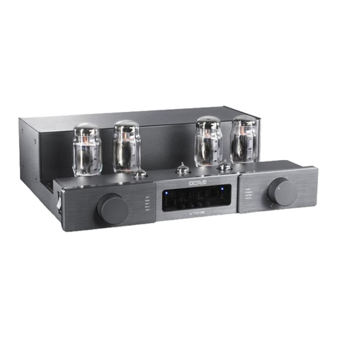
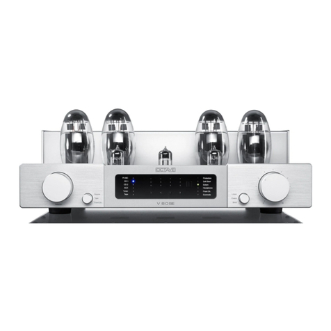
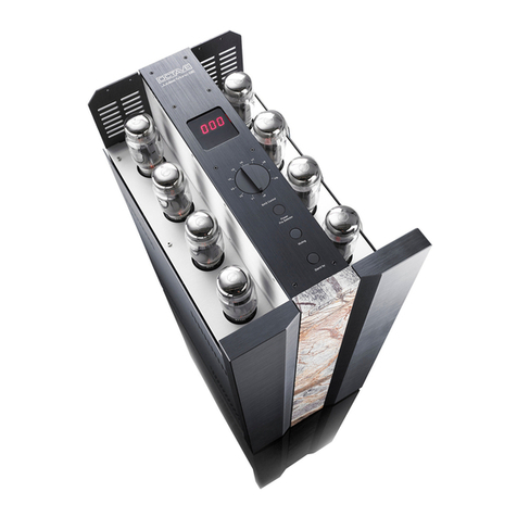
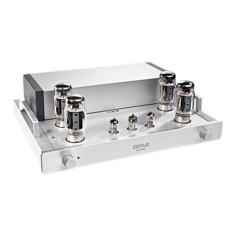
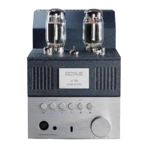
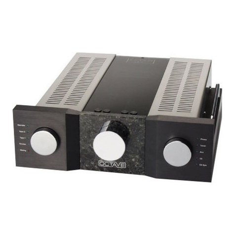
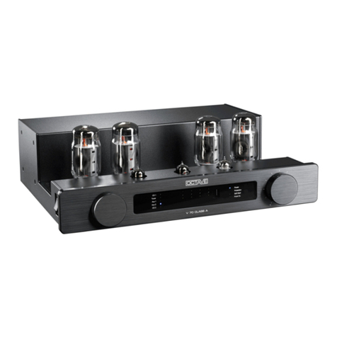
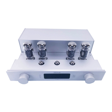
Octave V70 User manual

V70

3
INTRODUCTION
Congratulations and thank you for choosing the OCTAVE
V 70
You are about to enjoy the benefits of one of the world's most innovative and reliable
amplifiers. Take care of it, and your amplifier will provide you with many years of
listening pleasure.
You often hear people claim that there has been no real progress in tube amplifier
design for years. The operating principles of tubes have been documented
extensively and are well known to amplifier designers. The same can, of course, be
said for transistor amplifiers.
Nevertheless, there is still room for further development with both of these
technologies. This is both necessary and desirable. With tube amplifiers in particular,
a general reluctance to depart from the classic circuit designs has not done the
technology any favours. Today's loudspeakers and source equipment provide better
performance than ever before, but also make greater demands on amplifiers. Modern
sound reproduction equipment delivers a level of performance at a price that simply
would not have been possible 20 or even 10 years ago.
These advances have been achieved through the application of cutting edge
technology as it becomes available and affordable.
Integrating these technologies into amplifier design demands a detailed knowledge of
the inner workings of amplifiers and an appreciation of the sonic ramifications of each
modification.
We have specialized in tube amplification for the past 20 years, during which time we
have developed a number of innovative technologies that have earned us a
reputation as one of the leaders in the field.
We hope you will enjoy many hours of wonderful music with your OCTAVE amplifier.
Andreas Hofmann

5
CONTENTS
Page
Introduction ................................................................................................. 3
1. Description of the V70...................................................................... 7
2. Safety instructions............................................................................ 9
2.1. Before you begin.............................................................................. 9
2.2. Placement ........................................................................................ 10
2.3. Warranty........................................................................................... 10
3. Setting up......................................................................................... 11
3.1. Connecting the amplifier .................................................................. 11
3.2. Running in........................................................................................ 11
4. Operation: V70 front panel .............................................................. 12
5. The BIAS measurement system ...................................................... 14
6. Connections: V70 rear panel ........................................................... 15
7. Tubes
7.1. Removing the grille .......................................................................... 16
7.2. Tube layout....................................................................................... 16
7.3. Tube service life............................................................................... 17
7.4. Replacing tubes................................................................................ 17
8. Programmable remote control.......................................................... 18
9. Using the Black Box or Super Black Box ........................................ 19
9.1. Option: External Black Box .............................................................. 19
9.2. Option: External Super Black Box.................................................... 20
10. Troubleshooting................................................................................ 21
11. Technical data and dimensions........................................................ 22
12. Specification..................................................................................... 23
13. FAQ.................................................................................................. 24

7
1. DESCRIPTION OF THE V70
The V 70 is an integrated amplifier with a push-pull pentode output
stage producing approx. 2 x 70 W at 2% THD.
LOAD STABILITY Through optimization of the pentode design, we have developed a
power amplifier section with exceptional load stability. This load sta-
bility is important because the minimum impedance of modern, high
performance loudspeakers can be anywhere between 2.5 and 8
ohms. As impedances under 4 ohms are relatively common, we have
optimized our output transformers for 4 ohm loudspeakers. There is
no provision for 8 or 16 ohm outputs because:
1. There are practically no true 8 or 16 ohm loudspeakers being
made any more.
2. A properly optimized output transformer with additional tappings
would make the design very complex and would also add unneces-
sarily to the cost. It is not harmful to drive an 8 ohm loudspeaker from
a 4 ohm output. The amplifier simply delivers slightly less power into
an 8 ohm load.
ELECTRONIC
STABILIZATION The really new feature of the V 70 is the electronic stabilization of the
preamp power supply .
Because of the high voltages involved, the technology is highly so-
phisticated. First used in the Jubilee monoblocs, this technology is
particularly beneficial to the sound quality of smaller amplifiers. Inter-
action of the power amplifier with the sensitive input stages is elimi-
nated. The sound gains more silence, without any sense of edginess
- an effect normally only achieved with "giant" power supplies. Bass
reproduction also gains in authority.
POWER
MANAGEMENT Preamplifier stabilization is integrated with the electronic soft start
surge control (power management).
Soft start - ramping up of the heating and supply voltage at turn-on -
is
extremely important for the life and the sound performance of the
tubes. It also relieves the power supply components of the strain of
handling huge surge currents at turn-on.
During start-up, the Wait LED lights up on the front panel. When it
goes out, the amplifier is ready for use. Soft start is also activated
whenever there are strong fluctuations in the supply voltage, such as
may occur during thunderstorms.
PROTECTION
SYSTEM Many manufacturers fail to incorporate electronic or even passive
protection systems in their tube amps, which means that the life - and
indeed the operational safety - of these amplifiers is greatly depend-
ent on factors over which the user has no control.
We refuse to leave safety and service life to chance.
OCTAVE fits its power amplifiers with an electronic protection system
as a matter of course.
8
1. DESCRIPTION OF THE V70
Our protection system incorporates an independent circuit that monitors
the power output of the four power tubes. It switches the power supply
off when the maximum permissible values are exceeded. The red OFF
LED illuminates to show you when the protection has been activated.
This can happen for a number of reasons - for example, if the speaker
outputs are short circuited or if the power amplifier is overdriven. The
protection system protects the amplifier and the tubes from overload.
The V 70, like all Octave amplifiers, is thus fully protected against the
possibility of serious damage that often affects other valve amplifiers
when overdriven.
Our system - soft start and protection circuit - rules out any possibility of
'user error'.
Owners of tube amplifiers usually receive lots of advice like: Never op-
erate without the speakers connected; Follow the switch-on sequence
exactly; Switch valve amplifiers on and off as little as possible, etc. This
is certainly important advice for many amplifier brands, but is not neces-
sary with the V 70. The built-in control system automatically takes care
of this.
PROTECTION
SYSTEM
Another extremely useful feature is the bias (idle current) measuring
facility.
Unlike the simpler class-A power amplifier type, AB amplifiers require
adjustment of the negative grid bias to optimize idle current for the po-
wer tubes. The setting can change as the tubes age and it must also be
adjusted whenever tubes are replaced. Normally, this requires test e-
quipment and a knowledge of what and where to measure.
Setting the bias used to be a job for an electronics technician, but with
the V 70, you can check and adjust the bias without any tools while the
amp is on.
This adjustment has a huge influence on the sound quality and perform-
ance characteristics of an amplifier (see diagram 1 under "Specifica-
tion").
BIAS
All of these features make the V 70 a unique product in its class and a
true, state-of-the-art design. The V70 benefits from the know-how and
technologies that make our top of the range amplifiers, the Jubilee Line,
reference class products.

9
2. SAFETY INSTRUCTIONS
2.1. Before you begin
Before using your V 70, please remove the protective grille and install the output tubes supplied
with your amplifier in the appropriate sockets (see Removing the Grille and Tube Layout). Replace
the grille before switching on.
Operating the amplifier without its protective grille is dangerous and not recommended.
In case of emergency: disconnect the plug from the mains supply
Never use an amplifier that is damaged or faulty. Make sure that it cannot be used until it has been
repaired by a qualified service engineer.
Make sure that there is easy access to the IEC socket and power cord.
Do not open the case
There are dangerously high voltages and hot tubes inside this equipment. To avoid a burn or the
risk of electric shock, never allow anyone except qualified personnel to open the case or remove
the grille.
Servicing and maintenance
For reasons of safety, please ensure that servicing, repairs and other modifications to OCTAVE
equipment are carried out only by a qualified technician. Fuses should also only be changed by a
qualified technician. Always replace fuses with ones of the same type and rating. If your amplifier
requires servicing, please ship or take your equipment directly to OCTAVE or to one of our author-
ized service centres.
Explanation of the warning symbols:
The exclamation point within an equilateral triangle is intended to alert the
user to important operating and maintenance instructions.
The lightning flash with arrowhead symbol within an equilateral triangle is
intended to alert the user to the presence of uninsulated 'dangerous volt-
ages' within the product's enclosure that may be sufficient to constitute a
risk of electric shock to persons.
Before connecting
Make sure that the voltage of your amplifier matches your electricity supply voltage.
Grounding
This amplifier is a protection class 1 device (with an earth conductor). To exclude the risk of electric
shock in the event of a fault, the unit must be grounded. Use a three-core mains cable with a three-
pin plug (supplied).
Safety warning: hot tubes!
Warning: Remove the protective grille at your own risk. OCTAVE accepts no responsibility for inju-
ries caused by the removal of this grille.

10
2. SAFETY INSTRUCTIONS
2.2. Placement
1. Location
OCTAVE equipment is designed strictly for use in a dry domestic environment. Do not use it in the
open air or in damp environments!
Never place plants or liquid filled containers on your OCTAVE equipment. Take care that objects
do not fall or liquids are not spilled into the enclosure. Should this happen, remove the mains plug
immediately and have your amplifier checked by a qualified service technician.
Condensation may form if the amplifier is taken from a cold environment into a warm one. If you do
this, wait until the amplifier has reached room temperature and is dry before switching it on.
Avoid installing the unit close to sources of heat such as radiators or anywhere that it may be in
direct sunlight.
Do not operate the unit near flammable materials, gases or vapours. Avoid areas where there may
be heavy accumulations of dust or where the unit may be subject to mechanical vibration.
Place your OCTAVE amplifier on a stable, even surface.
2. Grille
Never operate the amplifier without the protective grille.
3. Ventilation
Make sure that your amplifier has a good flow of air around it. If you intend to install your equip-
ment in a cupboard or a shelf unit, ensure that there is at least a ten centimetre gap between the
ventilation slots and the walls all around the amplifier. The rear panel of cupboards should have
ventilation holes to prevent heat build up. Do not rest the equipment on a soft surface such as car-
pet or foam sheeting.
2.3. Warranty
OCTAVE can only guarantee the safety, reliability and performance of this unit if modifications and
repairs are carried out by specialized personnel and if the amplifier is operated in accordance with
the instructions contained in this manual.

11
3. SETTING UP
3.1. Connecting the amplifier
1. In your own interest, please observe the Safety Precautions and positioning advice
(Chapter 2)
2. Before connecting your OCTAVE amplifier up, switch off all the other equipment that you intend
to connect to it. This will avoid a source of possible problems when you plug these components
in.
3. Connect the cables from your signal sources such as CD player, tuner, etc. to the appropriate
inputs on the amplifier. When connecting recording devices, be careful to connect the recording
and replay inputs and outputs correctly.
4. Connect your loudspeakers to your V 70 amplifier, making sure that you observe the correct
polarity (positive on the amplifier to positive on the speakers).
5. Check that the amplifier is switched off before connecting the power cable to the
wall socket.
Before connecting the optional outboard Black Box, ensure that it is switched off.
(see Chapter 9, Black Box)
6. Now switch the amplifier on using the power (on/off) switch (see Chapter 4, Operation)
After switch-on, the ‘Wait’ LED will illuminate in addition to the normal power LED. The amplifier
is ready for use as soon as this LED goes out.
7. Check that the volume control is not set at maximum before playing music through the amplifier.
8. Switch the other components on in any order.
3.2. Running in
All OCTAVE equipment is subject to a 48-hour soak test at the factory to burn in the tubes. The
tubes are preselected for use in each particular model.
The sound quality of tube equipment improves throughout the initial running-in period of up
to three months.
During this time, daily use is beneficial (even at high levels) but not a requirement. Continuous
operation does very little to help reduce the running-in time and is therefore not recommended.

12
4. OPERATION - The V 70 front panel
Tape
CD
Aux
Tuner
Phono
On
Off
Bias
Wait
Power switch 0 = off; 1 = on. 'ON' LED lights up
During start-up, the ‘Wait’ LED also lights up. (see )
Selector switch For selecting the following inputs (clockwise):
CD, Tuner, Phono, Aux, Tape and bias adjustment (indicated by bias
LED on the right hand side of the display panel)
Input selector The LED lights up in the display to show which source is active.
CD Line level input for CD
Tuner Line level input for tuner
Phono Line level input for external phono module
Aux Additional line level input for video, etc.
Tape Tape playback. This type of input selector used does not
permit off-tape tape monitoring. If you wish to record a
CD, for example, the input must be switched to CD.
Switching to the Tape input would interrupt the recording.
Setting the bias See chapter 5, The BIAS measurement system
Remote receiver To ensure trouble-free operation of the remote control, never
obscure this area.

13
4. OPERATION -The V 70 front panel
Status indicators On (green LED) Lights up when the amplifier is on.
Off (red LED) Lights up when the electronic
protection system has switched the amplifier off in
response to an amplifier fault. (see ‘Description of the
V70’)
Bias (yellow LED) Lights up when the bias measurement
facility is switched on (see and Chapter 5, BIAS)
Wait (yellow LED) Lights up during the soft start process
immediately after switch-on. This LED goes out after
about 1 minute when soft start has been completed.
When there are mains supply interruptions (of the kind
that occur during thunderstorms, for example), soft start
cuts in automatically to restart the amplifier.
Volume control Motorized potentiometer

14
5. THE BIAS MEASUREMENT SYSTEM
How to set the bias
V1 V2 V3
V
4
Bias
Regulators for tube
V1 V2 V3 V4
The bias measurement system
The bias measurement facility makes it easy for you to check and adjust the idle current of the
output tubes. Getting the bias setting right for all four tubes is critical both for the sound of the
power amplifier section and for the service life of the tubes. It guarantees consistent sound quality
over the entire lifetime of the output tubes.
This is why we have built a bias measurement facility into the V 70 that allows you to carry out the
adjustment yourself without the need for test equipment. Thanks to the use of precision op amps,
this system allows you to set the bias to an accuracy of 0.3%, making it superior to any other ad-
justment method.
The use of selected output tubes only makes sense if the idle current is adjusted accurately, as is
clearly shown in Fig. 1 Technical Data.
Turn the Input/Mode selector switch clockwise until the bias LED lights up showing that the meas-
urement circuit has been activated. The 3 LEDs above each adjustment screw in the display panel
indicate that the bias setting is either too low, correct, or too high. Use the screwdriver supplied to
adjust the bias.
Turn the screws clockwise to increase the current. To ensure accuracy, all inputs are automatically
disconnected when the measurement function is selected.
The adjusting screws are fully insulated. There is no risk of electrical shock and the adjustment
procedure is completely safe.
The LED display:
top row: red LEDs Setting is too high
centre row: green LEDs Setting is OK
bottom row: yellow LEDs Setting is too low

15
6. CONNECTIONS: V70 rear panel
rec play
CD Tuner Phono Aux Tape
220-240V 50/60Hz
max.: 450W
ٛ
Integrated tube amplifier
V 70/II
Serial No.:
made in Germany
RL
+
_
Pre-out
Achtung!
Caution!
Black Box nur bei
ausgeschaltetem
Gerät anschließen
bzw. abtrennen!
Disconnect the
amp from mains
before connecting
the Black Box!
CD Line level input for CD
TUNER Tuner line level input
PHONO Line level input for external phono module
Aux Additional line level input for video, etc.
TAPE REC Output for a tape or DAT machine
TAPE PLAY Output for a tape or DAT machine
Pre-out Regulated preamp output for active subwoofer and so on
Loudspeaker outputs Speaker connection terminals
Black Box connection The Black box is an outboard power supply upgrade for the
power amplifier (see chapter 9. Black Box )
The V 70 must be switched off using the power switch
before connecting and disconnecting the Black Box.
Power connection Mains AC receptacle, IEC socket combined with mains
fuse holder. The rating of the fuse is depending on your
local mains voltage.
Model identification plate Model and serial number.

16
7. TUBES
7.1. REMOVING THE GRILLE
To remove the grille:
1. For your own safety, switch the amplifier off using the on/off switch.
2. Release the two M4 socket head bolts on the right and left of the grille.(Scope of delivery
includes an allen wrench)
3. Pull the grille upward to remove. (The nuts that these bolts screw into are the captive type.
They will not fall into the casing when fully unscrewed.)
7.2. TUBE LAYOUT
Output tubes: V1 - V4: 6550 fitted as standard
Possible alternatives are KT88, 6L6, and KT66
V1 + V2 left channel
V3 + V4 right channel
Driver tubes: V5 ECC83 (E83CC) = input tubes
V6 ECC88 (E88CC, 6922) = driver tubes
both channels use the V5 and V6 output driver tubes

17
7. TUBES
7.3. TUBE SERVICE LIFE
Thanks to the protection circuits and soft start electronics, the output tubes used in your
amplifier should achieve an average service life of 5 years.
The driver tubes can last for 10 years or more.
Because the tubes have different service lives, you will never have to renew the entire tube
complement at the same time.
Please note that some tubes need a long time (up to 300 hours) to achieve their optimum
sound quality.
7.4. Replacing tubes
Driver tubes
Replacement driver tubes require no adjustment.
Output tubes:
General procedure:
1. Switch the amplifier off and allow it to cool down for 10 minutes. Remove the old
tubes and fit the new ones.
2. Before you switch the amplifier back on, turn all bias adjustment controls
counterclockwise (this reduces the anode current substantially). You will
hear a click when the controls reach the minimum setting. These con-
trols are three-turn potentiometers, i.e. it takes three revolutions to go
from the maximum to the minimum setting.
3. Switch the amplifier on. After the ‘Wait’ period, all 4 minus-LEDs should illuminate yel-
low. If at this stage any of the LEDs are green or red, this indicates a faulty tube that
must be replaced.
3.1. New, untested output tubes should be burned in with a low anode current. To do this,
leave the amplifier on for 2 hours. Then adjust all the tubes.
3.2. Original Octave tubes
There is no need to burn in original Octave replacement tubes. After re-
placement, leave the power on for 10 minutes to allow the amplifier to
warm up. Then, adjust the bias.

18
8. PROGRAMMABLE REMOTE CONTROL
Select your OCTAVE amplifier on the touch screen panel with button AUX. Once selected you
can always control the volume directly by pushing the button Vol + or Vol - .
Detailed information relating the use of the remote control you find in the owner's manual of the
HOME THEATRE MASTER REMOTE
9. USING THE (SUPER) BLACK BOX
Description
OCTAVE, with the Black Box technology, offers an instrument to optimizing the OCTAVE amplifier
in respect to the speaker. This flexibility is a unique feature of the OCTAVE brand.
The dynamic and tonal stability of an amplifier is strongly dependent upon the stability and capacity
of the power supply, therefore the Black Box and Super Black Box were developed as external
upgrades to the OCTAVE amplifiers’ power supply storage capacitors by increasing their capaci-
tance by a factor of 4 (Black Box) or 10 (Super Black Box), respectively. This is a tremendous
benefit if the speaker is difficult to drive. Loudspeaker efficiency is made less critical, while the am-
plifier is enabled to handle speakers with minimum impedances as low as 2 Ohms.
The power supply capacitance increase realized via use of the Black Box or Super Black Box stabi-
lizes current delivery and reduces the impedance interaction of the load. This improves dynamic
range, separation, depth, soundstage size and articulation, rendering the musical reproduction
clearer throughout the entire frequency range. The amplifier remains unaffected by mains varia-
tions and interferences due to the noise filtering characteristics of the capacitors
Device selector OCTAVE code B
Volume up
Volume down

19
9. USING THE (SUPER) BLACK BOX
9.1. Option: External Black Box
Black-Box
Indicator LED High-current plug
The LED lights up continuously when the power amplifier is on. The LED goes out when the protec-
tion circuitry trips. This is normal, as the protection circuitry cuts the power to the amplifier.
Specifications:
Dimensions: Width x height x depth = 170 x 97 x 257mm
Weight: 3.1kg
Connection cable: 70cm long. Longer lengths available upon request
Connecting to the amplifier
Warning!! Before connecting the Black Box, switch the unit off using the power
switch and wait for 1 minute.
When inserting the connector, guide the anti-rotation lug carefully into the mating
recess in the socket.
When you switch the amplifier on, the LED on the front panel of the Black Box will
illuminate.
Please note:
When the amplifier's electronic protection circuitry cuts in, this will cause the LED
on the Black Box to go out, as it interrupts the power to the amplifier.
Should you wish to disconnect the Black Box, switch the amplifier off first and wait
until the LED on the Black Box goes out before doing so.

20
9. USING THE (SUPER) BLACK BOX
9.2. Option: External Super Black Box
Blue Power LED:
The blue Power-on LED illuminates when the power amplifier (or integrated amplifier) is
switched on via the amplifier's power on/off switch.
Yellow Discharge LED:
When the power amplifier is switched off, the yellow Unload LED illuminates for about 2 sec-
onds. This indicates that the rapid discharge circuit is discharging the electrolytics in the SBB.
The discharge circuit also activates if the SBB connecting cable is removed accidentally. This
makes it impossible for an SBB to contain a dangerous charge while it is disconnected.
Dimensions and weight
Dimensions: (Width x height x depth) = 203 x 159 x 320mm
Weight: Approx. 7.5kg
Connection cable: 80cm long. Longer lengths available upon request
Connecting to the amplifier
see Black Box

21
10. TROUBLESHOOTING
Hum and crackling
Hum in an audio system is often caused by several system components being earthed individu-
ally. It is particularly common with tuners, VCRs or satellite receivers where the earthed aerial
cables can cause a hum loop via the aerial input.
Tube power amplifiers are normally earthed, and the V 70 is no exception. However, removing
the earth wire on your mains plugs is not a solution, You can isolate the aerial earth connection
with a special signal isolator. This device has no adverse affect on the sound or picture quality
of tuners or TVs.
Check also that the phono plugs are a tight fit. Bend the outer earth contact inwards slightly if
necessary. Sometimes the internal pin in a phono plug may not be a tight enough fit, in which
case you should change either the interconnect cable or the socket.
Switching interference
Older fridges and 12 V halogen lamps can cause cracking through the loudspeakers when they
switch on and off.
Solution: The only solution is to use a single power socket board for your entire system and to
use a different power outlet in your listening room. However, it is not always possible
to eliminate the problem entirely.
Channels are not balanced
1. Damaged cables and poorly fitting phono plugs can create resistance in the signal path
enough to reduce the output level of one channel.
Solution: Try new cables or clean the plugs and sockets with isopropyl alcohol.
2. A tape or DAT machine connected to the REC Out may have a faulty Record input (or
faulty interconnect cable) causing the signal to overload. This can result in an imbalance
between the left and right channels.
Solution: Disconnect the tape/DAT machine
3. A faulty output tube can cause a drop in output in one channel and generate distortion at
higher output levels.
Solution: Locate the defective tube using the bias adjustment facility. Replace the
tube.
Increased hiss on one channel
An irregular hissing sound is a sign of a worn driver tube.
Solution: Replace the worn tube.

22
11. TECHNICAL DATA AND DIMENSIONS
In- and Outputs:
Inputs: 5 x RCA, including one optional Home Theatre Bypass input
Outputs: 1 x RCA Record output, 1 x regulated Preamplifier
output, 1 x Loudspeaker output
Amplifier
Power output: 2 x 70 W / 4 ohms
Frequency response 10 Hz - 80 kHz / 0.5 dB
Total harmonic distortion 0.1% at 10 W into 4 ohms
Signal-to-noise ratio 100 dB
Minimum load impedance 2 ohms
Input sensitivity 120 mV, normal gain
700 mV, low gain
General
Power consumption 130 W minimum, 320 W at full power
Weight: 21.6 kg
Standard accessories power cable,
3mm slotted screwdriver for BIAS measurement,
Allen wrench 2 mm for removing the grille
IR remote control
Dimensions Overall dimensions in mm

23
12. SPECIFICATION
Features
- Remote control as standard
- Input selector via gold plated relays
- Gold plated phono sockets
- Double sided PCBs with plated through holes
- Ceramic tube bases with silver contacts
- Specially selected longlife, burned-in tubes
- Professional, low inductance reservoir electrolytics, LH grade
- Modular aluminium case
- Available in a range of anodized colours
Distortion at 4V into 6 ohms between 30 Hz and 20 kHz
at a variety of bias settings
Diagramm 1
Curve 1: Bias adjusted correctly
Curve 2: Bias 10% out
Curve 3: Bias 30% out
Frequency response right and left channel, 4 V into 4 ohms
+0
-20
-17.5
-15
-12.5
-10
-7.5
-5
-2.5
d
B
r
B
10 40k20 50 100 200 500 1k 2k 5k 10k 20k
Hz
The frequency response for both the left and right channels
measures within extremely tight 0.2 dB limits from 10 to
40 kHz .
Table of contents
Other Octave Amplifier manuals

Octave
Octave V 80 SE User manual

Octave
Octave V 50 MKII User manual

Octave
Octave JUBILEE Pre User manual

Octave
Octave V110 User manual

Octave
Octave JUBILEE Mono User manual

Octave
Octave Phono Module User manual

Octave
Octave v70se User manual

Octave
Octave HP 300 SE User manual

Octave
Octave JUBILEE MONO SE User manual

Octave
Octave RE290 User manual

Octave
Octave RE 280 MK2 User manual

Octave
Octave Phono EQ.2 User manual

Octave
Octave Phono Module User manual

Octave
Octave HP 300 MK2 User manual

Octave
Octave Black Box User manual

Octave
Octave HP 700 User manual

Octave
Octave RE 320 User manual

Octave
Octave JUBILEE 300 B User manual

Octave
Octave Super Black Box User manual

Octave
Octave HP500MK3 User manual