All dimensions in mm. All figures are illustrations of photos. Changes reserved
3
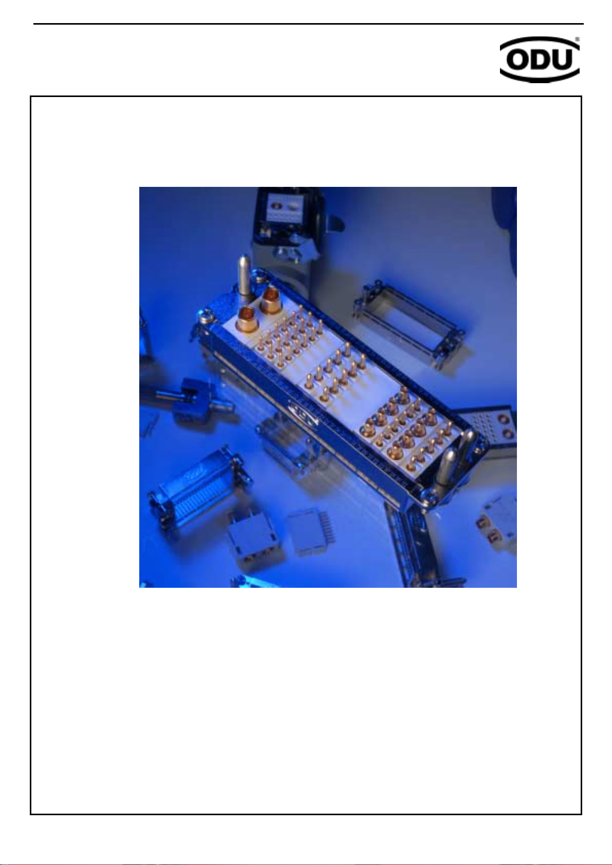
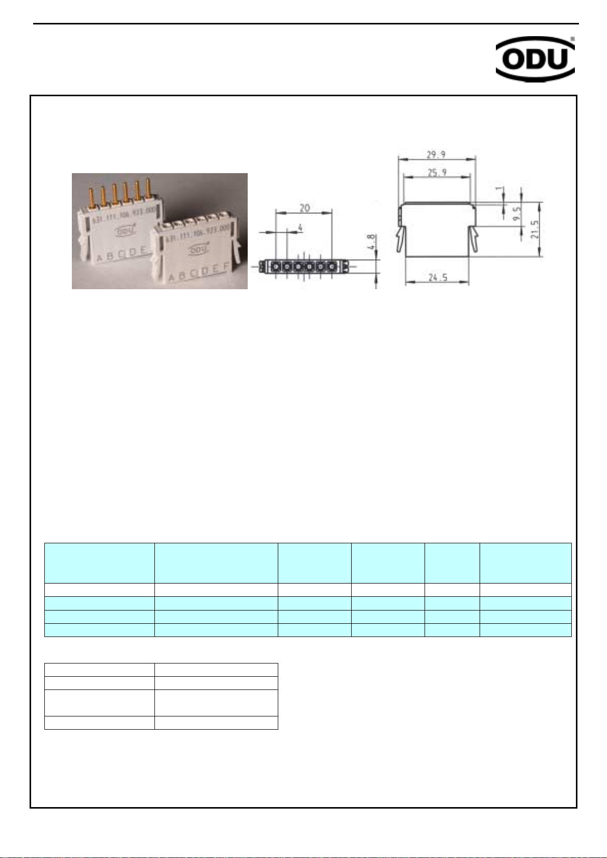
ODU MAC LC
Modular Attachable Connector
The new ODU MAC LC is mainly designed for the use as a service- and interface connector.
The main application areas are e.g. machine construction, measurement, medical
technology etc.
Most interface connectors in the area of machine construction are often actuated only a
few times. For this kind of application the new ODU MAC LC offers clear price benefits
because of the ODU standard contact technology.
ODU MAC LC is an economical alternative with proven ODU contact technology using
turned/slotted contacts up to 5,000 mating cycles.
The economic aspect is reinforced by the simple processing of the contacts and modules.
User-friendly assembly and removal, even when assembled, distinguish the ODU MAC LC
as a service connector.
The new system offers many advantages for the user.
!Economical interface solution in premium quality
!Proven ODU contact technology
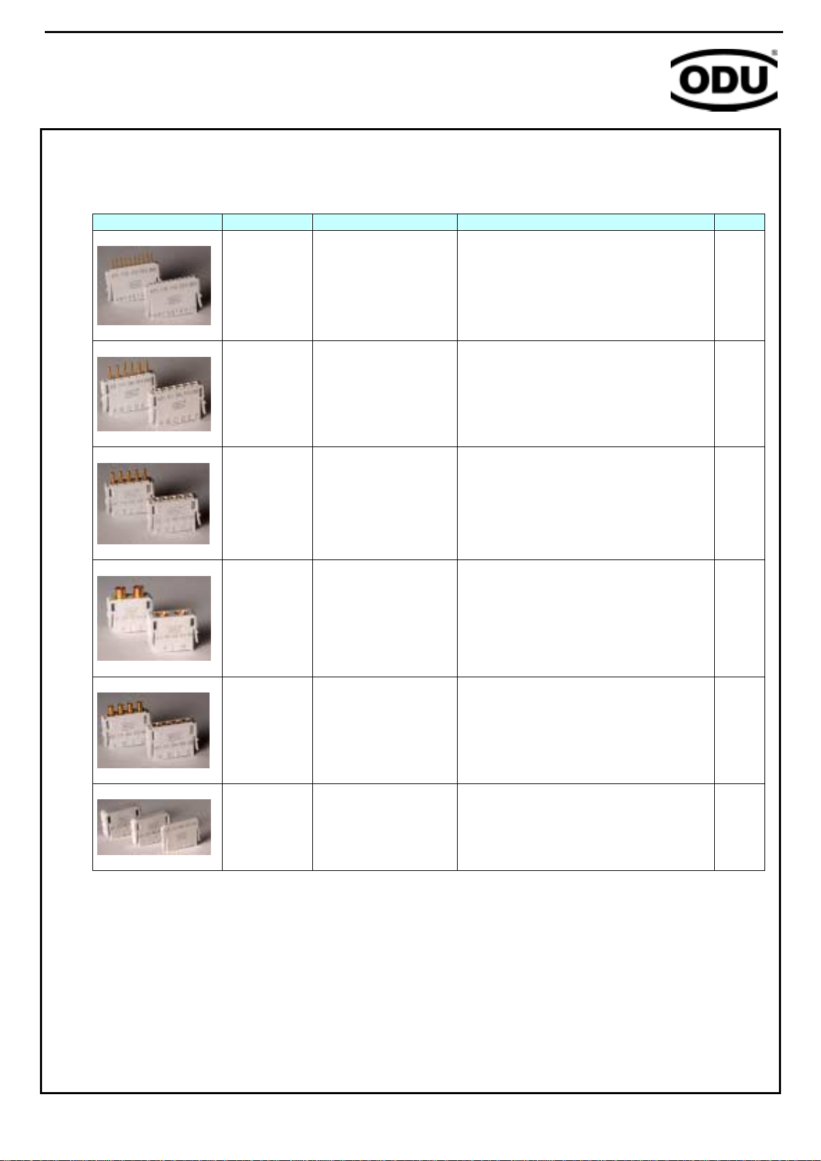
!4 frame sizes
!Different contact inserts (Modules) available
!Centering and keying using the guiding system, frame is grounded
!Easy assembly and removal of the contact using clip technology
!Simple, quick packaging and module assembly in the frame
!Tool-less disassembly of the modules
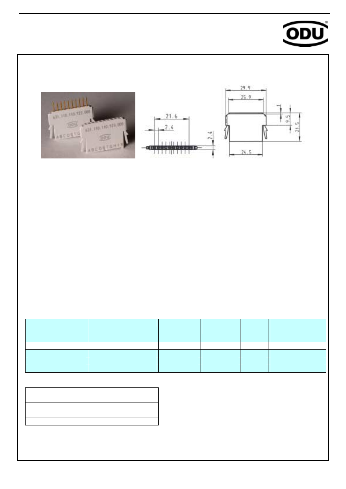
!Frame can be mounted in standard DIN housing
!High connector density (370 signal contacts available in size 4 frame)
.
ODU MAC LC – Product Information