Page 7
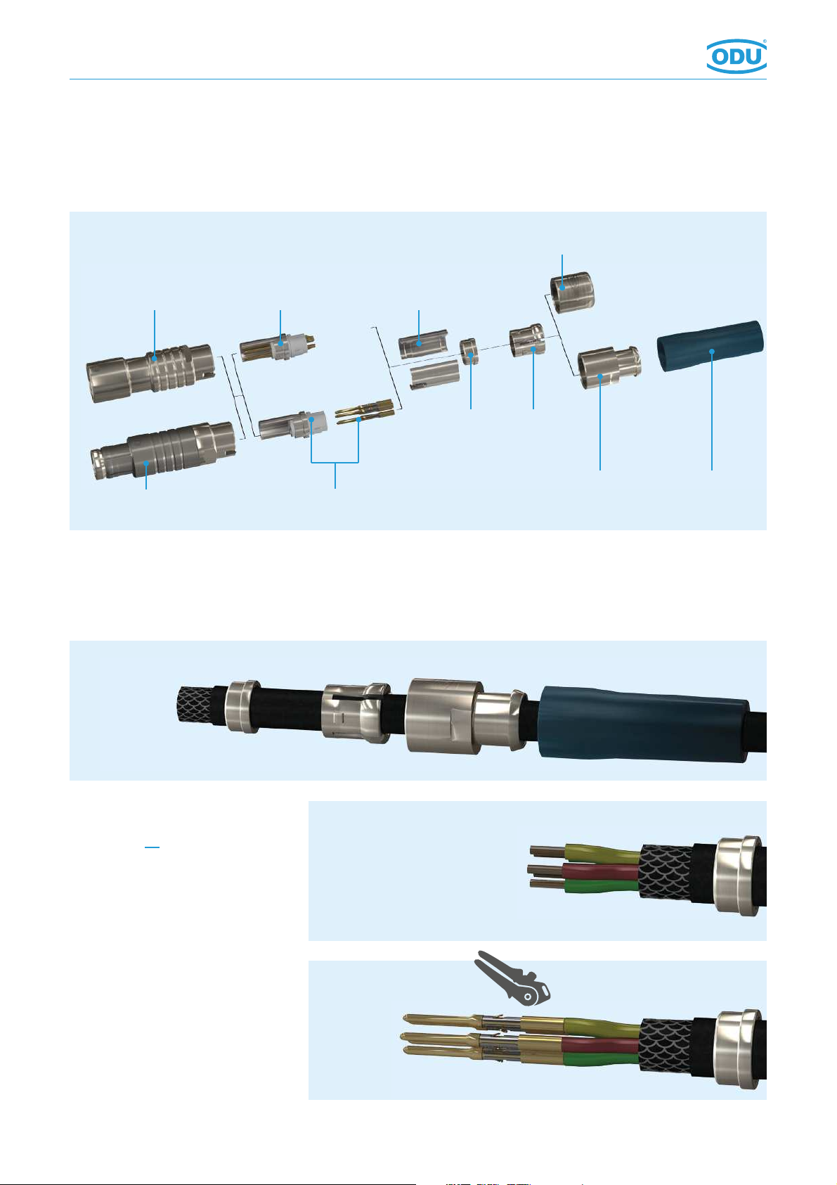
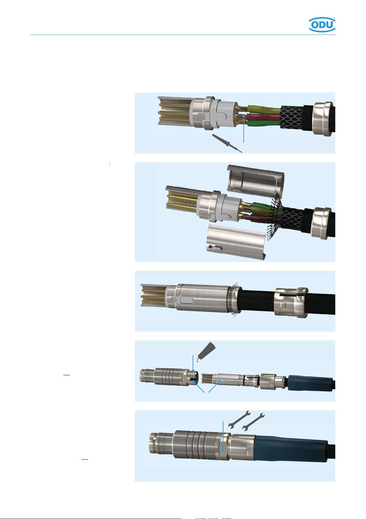
4. Insert contacts into insulator
according to contact arrangement.
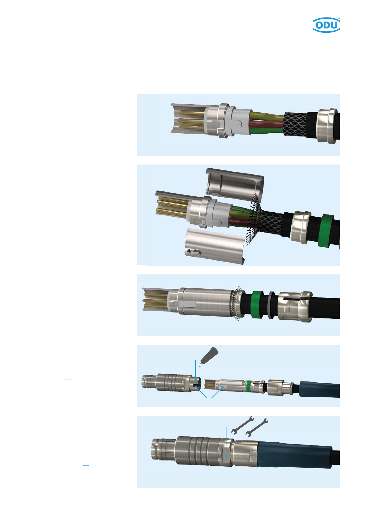
5. Bend cable shield outwards,
assemble half shells.
6. Slide the EMI ring, sealing, washer
and the cable collet against the
half-shells and clamp the shield
against it.
7. Put the assembled cable
considering the guidings (B) in the
connector housing. If necessary,
secure thread (A) with adhesive
(see page 18).
8. Screw back nut on the assembled
plug, counterhold by means of the
spanner at (C) and hold against
with ODU spanner wrench.
Caution! Consider tightening
torque (see page 18).
The assembly is nished.
010.055.000.000.000
Assembly Instructions