Office Fitness FitBike 1 DBT Guide

FitBike 1 DBT
Instructions / Manual / Maintenance
SAFETY PRECAUTIONS
Please read all instructions carefully before using this product. Retain this manual for future
reference. The specifications of this product may vary slightly from the illustrations and are
subject to change without notice.
Make sure you read and fully understand this instruction manual.
It is the user's responsibility to read and understand all potential hazards of the FitBike.
Consult a physician before you begin a new exercise program. If you experience pain, or
you feel faint, short of breath or dizzy, stop exercising and consult a physician. Incorrect
or excessive use of this machine can result in injury.
Your exercise bike should be operated on a stable, level surface.
Mount and dismount your exercise bike carefully.
Keep loose clothing, untied shoelaces, jewelry and towels away from the bike pedals.
This machine is not a toy. Keep children away from this exercise bike, especially while in
use. Children should be taught to never put their fingers near any moving parts on this
machine. Minors should not use this product, since it is built and intended for adults.
Remain seated while using bike - do not stand on pedals.
Maximum weight capacity of this bike is 242 lbs (110 kg).

A B
C
E
G
I
K
M
O
Q
D
F
H
J
L
N
P
8910 11
8 washer Self-drilling screw
(2 pcs)
M5x8 mm screws
(4 pcs)
Spring washer
(8 pcs)
12 3 4
M8x65 mm bolt
(4 pcs)
8x19 washers
(8 pcs)
M8x15mm nuts
(4 pcs)
Screwdriver
10, 13, 15, 17
56 7
Socket wrench Hex key 5x5mm M8x16 mm screws
(4 pcs)
A
M
J
B
C
N
K
LP
Q
G
E
D
8
F
I
O
H
PRODUCT PARTS AND OVERVIEW
ACCESSORY PACKAGE LIST

ASSEMBLY - STEP 1
Set the cart (A) on the floor. Attach the front stabilizer (8) to the cart (A) using two head bolts
(1) two washers (2), two spring washers (11) with two nuts (3). Use the enclosed screwdriver
(4). Next, attach the rear stabilizer (C) to the cart using two head bolts (1) and two washers (2),
two spring washers (11) with two nuts (3) as well. Use the enclosed screwdriver (4).
ASSEMBLY - STEP 2
Loosen the seat height
adjustment knob by turning
it, then pull it in order to
slide the seat frame (D) into
the base of the bike (A);
adjust the seat height then
release knob. When you
hear a click, the
spring-loaded knob is
supporting the seat frame at
the selected height. Now
tighten knob. Next, attach
seat cushion assembly (E) to
the seat frame (D), then lock
assembly (E) in place with
the seat cushion adjustment
knob (F) equipped with
washer (8).
B
C
A
Seat height
adjustment knob
Seat cushion
adjustment knob
1
1
2
2
2
3
3
3
11
11
11
E
D
F
8

ASSEMBLY - STEP 3
Take cushion out of its shipping bag,
then attach the seat cushion (G) to
the seat frame. Lock the seat
cushion firmly in place with the
socket spanner (5) and hex key (6).
ASSEMBLY - STEP 4
Install the pedals (H) (I) on the crank legs and
lock them firmly with the wrench side of the
wrench/screwdriver (4).
Note: The right and left pedals are different
and each is marked "R" or "L" to identify it.
Install each one on its correct side.
G
H
I
H

ASSEMBLY - STEP 5
Install the handlebar support frame (J) into the console tube (K), and attach the upper spinner
to lower spinner in console tube (see picture 1). Next, connect the cable in console tube (K) to
matching cable of the cart (see picture 2). Slide the console tube to cart, and connect them
with four MB x 16 mm screws (7) and four 8 x 19 washers (2), four spring washers (11). Lock
them using 5 x 5 mm hex key tool (6). Then attach the console mast (J) to the cart.
ASSEMBLY - STEP 6
Plug the handle bar tube (M) into the console, making sure the pulse sensor is down-forward.
Tighten knob (F). Connect the console module (L) to console tube by using M5 x 8 mm screws (10).
Link the two cables with white joint to handle
tube (M). Link the third cable of the console
to the console tube. Finally, adjust the
console position and tighten it in place using
screwdriver (4) and M5 x 8 mm screws (10).
picture 2
picture 1
1
2
3
4
pulse sensor
L
F
M
10
K
J
7
2
11

ASSEMBLY - STEP 7
Attach the left and right CONSOLE MAST (N and O) to the handle bar (M) and tighten them in
place using wrench (4) and M5 x 8 mm screws (10). Next plug the table (P) onto handle bar,
and plug cup holder (Q) to groove of the table.
P
Q
N
K
MO
9
10

COMPLETED ASSEMBLY PICTURE
Adjust the seat height, handlebar and pedal strap according to your height before doing
exercise.
Release the SEAT HEIGHT ADJUSTMENT KNOB
by adjusting it COUNTER CLOCKWISE and pull
the SEAT HEIGHT ADJUSTMENT NOB forward
to adjust the seat height. Move seat and release
knob; you will hear a click when seat locks in
place. Then tighten the SEAT POST adjustment
knob CLOCKWISE.
Adjust seat to
desired position by
pulling on
adjustment knob,
then turn knob
right to tighten
seat in place.
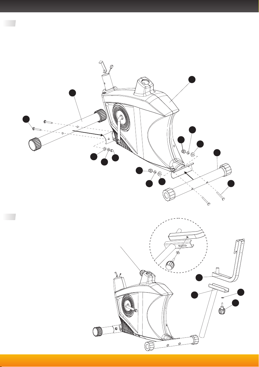
If the bike is unbalanced on
floor, adjust the foot pad
Pedal strap adjust: pull the
outer side straps hook, then fit
the appropriate length buckle
position into the hook inside.
Digital Display. Power Requirement:
2 'AA' 1.5 volt batteries. When
installing, align battery + side to
markings in container.
There are eight adjustable
resistance levels. Levels
increase from 1 to 8, with
level 8 having the most
resistance. To adjust, turn
the resistance dial in the
"+" direction for more
resistance and in the "-"
direction for less
resistance.
Higher
resistance
Lower
resistance

www.officefitness.co.uk
Keep Fit
at Work
CONSOLE OPERATION
The bike console is easy to use. One button controls how you can track your progress on the
display.
The MODE KEY let you select the form of progress data to show on the LCD display. Each time
you press it, the display moves to the next kind of progress data. You can choose things like
time pedalling, speed, distance travelled, calories burned, and more. The data type shows on
the LCD bottom line and the data value shows above that. For example, data type "DIS" is
distance travelled, and a data value number will appear above showing how many KM
(kilometers) you pedalled since reset. You can reset the progress data to zero by pressing and
holding the MODE KEY for several seconds. The display turns off automatically when there
has been no activity (pedalling, or key presses) for about 4 minutes. The display can be
activated again by pedalling or by pressing the MODE KEY.
LCD Display
MODE Key
Table of contents
Other Office Fitness Exercise Bike manuals