OfiTE 2025 User manual

Model 2025 Automated HTHP Consistometer
#120-35 - Consistometer
#120-35-DAS - With Computer
Instruction Manual
Updated 8/23/2022
Ver. 1
OFI Testing Equipment, Inc.
11302 Steeplecrest Dr. · Houston, Texas · 77065 · U.S.A.
Tele: 832.320.7300 · Fax: 713.880.9886 · www.ote.com
©Copyright OFITE 2022

OFITE, 11302 Steeplecrest Dr., Houston, TX 77065 USA / Tel: 832-320-7300 / Fax: 713-880-9886 / www.ote.com 1
Requirements .................................................................................3
Intro..................................................................................................3
Description......................................................................................3
Features...........................................................................................3
Specications .................................................................................4
Components ...................................................................................4
Safety...............................................................................................7
Quick Start ......................................................................................9
Starting a Test.............................................................................9
Completing a Test .....................................................................10
Setup.............................................................................................. 11
Software ........................................................................................16
General Setup...........................................................................16
Setup.........................................................................................17
Prole Builder............................................................................19
Main Screen..............................................................................21
Events .......................................................................................24
Calculated Values .....................................................................25
Onboard Display...........................................................................26
Real-Time Data.........................................................................27
Test Setup - Test Cong............................................................28
Test Setup - Prole....................................................................29
Calibrate....................................................................................30
Utilities.......................................................................................31
Archive ......................................................................................32
Manual Control..........................................................................33
Start Test...................................................................................34
Operation ......................................................................................35
Filling the Slurry Cup.................................................................35
Starting a Test ...........................................................................37
Completing the Test ..................................................................39
Table of
Contents

OFITE, 11302 Steeplecrest Dr., Houston, TX 77065 USA / Tel: 832-320-7300 / Fax: 713-880-9886 / www.ote.com 2
Maintenance .................................................................................40
Cleaning....................................................................................40
Potentiometer ...........................................................................42
Rupture Disk .............................................................................44
Oil Filter.....................................................................................45
Pressure Relief Valve Regulator...............................................46
Troubleshooting.........................................................................47
Calibration.....................................................................................51
Potentiometer ...........................................................................51
Value Chart ...............................................................................53
Pressure....................................................................................54
Temperature..............................................................................55
Cell Cap O-ring and Backup Ring.............................................56
Cell Diagram .............................................................................57
Slurry Cup Diagram ..................................................................58
Potentiometer Diagram .............................................................60
Potentiometer Adjustment.........................................................61
Fuses and Breakers..................................................................62
Multiple Instruments..................................................................63
Warranty and Return Policy ........................................................64

OFITE, 11302 Steeplecrest Dr., Houston, TX 77065 USA / Tel: 832-320-7300 / Fax: 713-880-9886 / www.ote.com 3
During cementing operations, the time required for a cement slurry to set is
of primary concern. Under an ideal situation, minimal time would be required
to successfully pump the slurry, which immediately upon placement, begins
fully pump the cement, it will be necessary to drill the cement remaining in the
casing string. Remedial operations such as this are very costly. Conversely,
cements that are successfully placed, but require considerable time to
cure, consume valuable rig time, which is also quite costly. Laboratory tests
should be conducted under simulated reservoir conditions to examine the
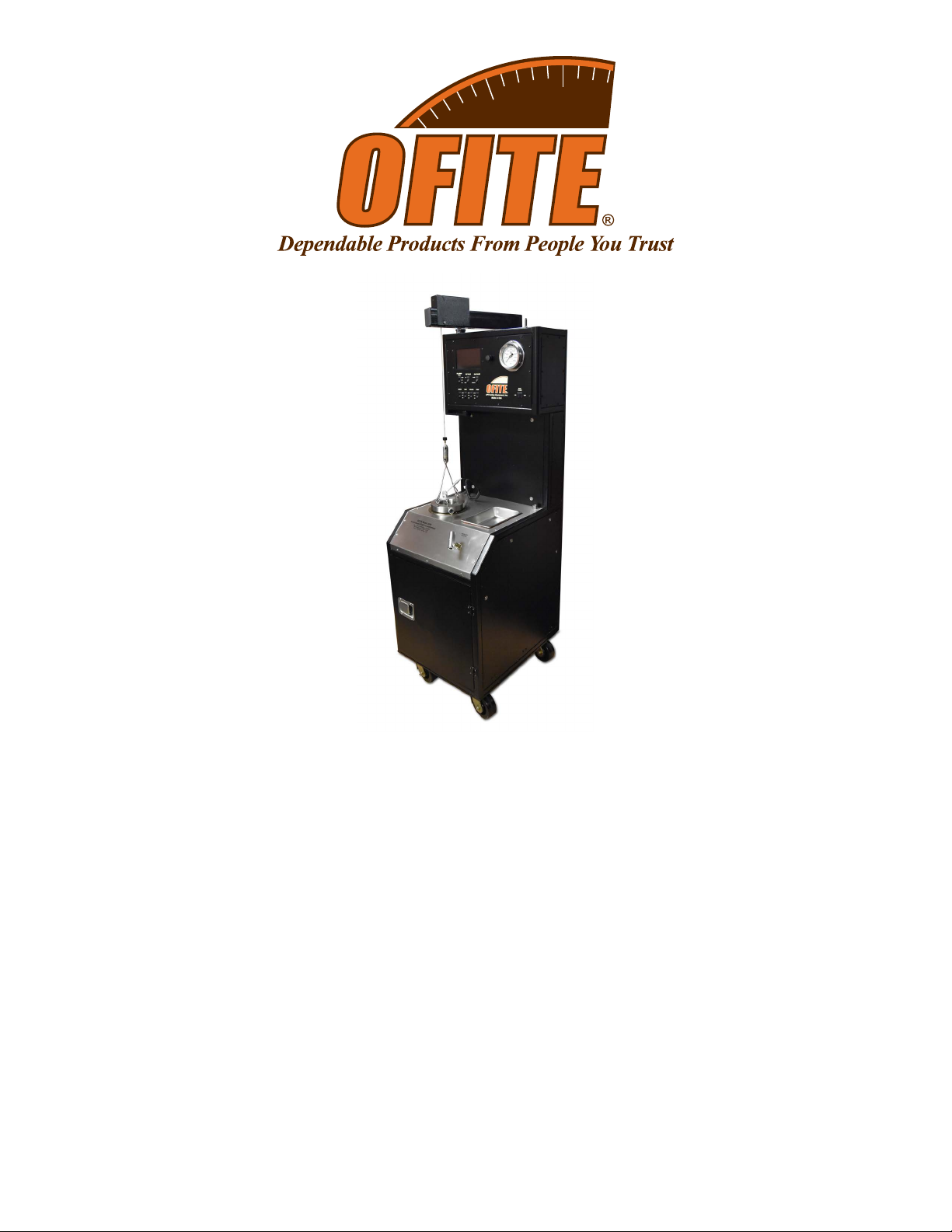
actual thickening time of the slurry. The OFITE HTHP Consistometer was
under simulated downhole pressures and temperatures.
A cement is mixed and poured into the slurry cup assembly. The slurry cup
is placed into the test vessel and pressure is increased via an air-driven
hydraulic pump. A PID temperature controller governs an internal heater,
mechanism rotates the slurry cup assembly. A potentiometer controls an
output voltage, which is directly proportional to the amount of torque the
cement exerts upon an API-approved paddle. The included software controls
the instrument and records temperature, pressure, and cement consistency
as a function of time.
- Touch screen display for standalone mode
- Computerized Data Acquisition and Control system provides detailed test
information in convenient formats and can control multiple units from one
computer. RS-232, Ethernet, and USB connections available.
- Automatic temperature and pressure control
- External cooling jacket aids cooling of test cell
- Automatic, programmable speed motor (0 – 300 RPM) powered by a
magnetic drive
- Drip tray next to cap provides a place to set the cap between tests without
dripping oil on the unit casing
- Convenient oil reservoir features a cap with built-in funnel to help prevent
spills, a removable top and bottom that make cleaning easy, and a sloping
bottom that collects sediment for easy removal
- Visual indicator provides an at-a-glance status update during testing
- Small footprint saves valuable lab space
- Temperature, pressure, and consistency alarms provide automatic
shutdown for safety
- Water Drain
Intro
Description
Features
Requirements

OFITE, 11302 Steeplecrest Dr., Houston, TX 77065 USA / Tel: 832-320-7300 / Fax: 713-880-9886 / www.ote.com 4
Specications Size
Weight
Crated Size
Crated Weight
Temperature Controller
Pressure Indicator
resolution. Analog gauge.
Slurry Cup Variable Speed: 0 – 300 RPM
Max Temperature
Max Pressure
tongs for heater shield, and lifting tongs for potentiometer)
Components

OFITE, 11302 Steeplecrest Dr., Houston, TX 77065 USA / Tel: 832-320-7300 / Fax: 713-880-9886 / www.ote.com 5
Potentiometer Components:
Slurry Cup Components:
Optional:
#120-35-SP Spare Parts Kit

OFITE, 11302 Steeplecrest Dr., Houston, TX 77065 USA / Tel: 832-320-7300 / Fax: 713-880-9886 / www.ote.com 6

OFITE, 11302 Steeplecrest Dr., Houston, TX 77065 USA / Tel: 832-320-7300 / Fax: 713-880-9886 / www.ote.com 7
Safety
Explanation of Symbols
Caution: Risk of Danger - This symbol directs the operator to consult the
Whenever this symbol is used on the equipment, the user must
consult the manual to determine the nature of the hazard and any
actions which have to be taken.
Hot: This symbol indicates that a surface may be hot to the touch.
Shock Hazard: This symbol indicates a risk of electrical shock.
Note: This symbol will indicate important notes and helpful hints for the
operation of the equipment.
Tip: This symbol is used to identify operational information and best
practices to obtain the most reliable data.
Caution: Note - This symbol is used to indicate statements in the manual
which warn against actions which may cause damage to the equipment
during routine service or maintenance.

OFITE, 11302 Steeplecrest Dr., Houston, TX 77065 USA / Tel: 832-320-7300 / Fax: 713-880-9886 / www.ote.com 8
• The Consistometer conforms to the relevant safety regulations; however
the user is solely responsible for the correct handling and proper usage of
the instrument.
• The equipment should be operated in such a way that will not endanger
people.
• The equipment must not be operated if there is any evidence of external
damage, leading to any doubt regarding safe operation.
• The user must comply with the instructions in this instruction manual,
otherwise safe operation cannot be guaranteed.
• This instruction manual must be readily available for all operators.
• Do not bend or stress connection cables and mains cable.
• Do not subject connection or mains cables to high temperatures (higher
• Check integrity of cables at regular intervals.
• The unit must be powered down before any cables are connected or
disconnected. This reduces the risk of electrostatic charging and resultant
damage to electronic circuit boards.
• The operator must have a good familiarity with the installation of the unit
and its surroundings.
• Suitable protective gear should be worn in the factory environment in
which the unit has been installed.
•
• The user is responsible for the safe handling of any materials tested. If in
doubt the material safety data sheet should be read, relevant safe han-
dling regulations should be read and observed and good operating and
manufacturing practices should be followed.

OFITE, 11302 Steeplecrest Dr., Houston, TX 77065 USA / Tel: 832-320-7300 / Fax: 713-880-9886 / www.ote.com 9
Quick Start
Starting a Test
Before turning on the Consistometer, make sure the MOTOR, HEAT,
2. Turn the MAIN POWER switch on.
3. Turn the MOTOR switch to ON.
Slowly lower the slurry cup into the test cell until the drive table engages
with the drive pins on the bottom.
Lower the potentiometer into the test cell so that it sits on top of the slurry
cup.
Turn the MOTOR switch to AUTO.
Carefully lower the cell cap into the test cell and tighten it.
Plug the thermocouple into the port near the test cell. Insert the
thermocouple into the hole in the top of the cell cap and tighten the thread
Close the pressure release valve by turning it clockwise.
Turn the FILL/DRAIN CELL switch to FILL. When the cell is full, oil will
seal the cell.
Leave the FILL/DRAIN CELL switch in the FILL position during
testing.
Load the test:
a.
b.

OFITE, 11302 Steeplecrest Dr., Houston, TX 77065 USA / Tel: 832-320-7300 / Fax: 713-880-9886 / www.ote.com 10
Quick Start
Completing a Test
When the test is complete, the red light on the Status Indicator will turn on
and an alarm will sound. To acknowledge the alarm, touch the alarm icon.
Stop the test:
a. If you are using the software to run the test, click the Stop Test button.
b. If you are using the onboard controls to run the test, touch the Stop
Test button.
3.
and slowly open the Pressure Release valve.
Never release pressure while the temperature is above 200°F
(93.3°C).
DRAIN. This will allow air into the test cell and force the oil back into the
reservoir.
When you hear air venting from the Consistometer, turn the FILL/DRAIN
Remove the thermocouple from the cell cap.
Unscrew the cell cap and remove it from the test cell.
Remove the potentiometer and the slurry cup from the test cell.
Return the cell cap to the test cell to prevent dust and other material from
entering the cell.

OFITE, 11302 Steeplecrest Dr., Houston, TX 77065 USA / Tel: 832-320-7300 / Fax: 713-880-9886 / www.ote.com 11
Setup Carefully remove the instrument from the wooden crate.
2. Once the unit is in place, lock the casters by depressing the lever on the
side. This will prevent the unit from moving.
3.
back of the instrument.
Connect the drain and coolant supply lines, also on the back of the unit.
The consistometer has two power inlets on the back of the cabinet. The
POWER inlet is optional. It powers the electronics only.
POWER into an uninterruptible power supply (UPS). In the event of a
continue to work and the test will keep running.

OFITE, 11302 Steeplecrest Dr., Houston, TX 77065 USA / Tel: 832-320-7300 / Fax: 713-880-9886 / www.ote.com 12
oil reservoir cap. Pour approximately four liters (or until full) of mineral oil
tight. Use the sight glass on the front to check the oil level.
Turn the “Main Power” switch On.
Calibrate the potentiometer before connecting the Consistometer to a
Reservoir
Cap

OFITE, 11302 Steeplecrest Dr., Houston, TX 77065 USA / Tel: 832-320-7300 / Fax: 713-880-9886 / www.ote.com 13
Thermocouple
Port
Cell Cap
Thermocouple
Storage
Pressure Release Valve
Onboard
Display
USB Port
Switches
Cell
Pressure
Scroll Wheel

OFITE, 11302 Steeplecrest Dr., Houston, TX 77065 USA / Tel: 832-320-7300 / Fax: 713-880-9886 / www.ote.com 14
Status Indicator:
The lights on the Status Indicator correspond to the consistency of the
sample. The threshold values can be set in either the onboard controls or
consistency (Bc).
-
green light will be on.
-
value, the green and yellow lights will both be on.
- Max Bc for Red Light: When the consistency is below this value, the
yellow light only will be on. When the consistency is above this value,
the red light will be on and the test will stop.
The Status Indicator also indicates an alarm condition. If an alarm is
triggered, all three lights on the status indicator will blink until the alarm is
acknowledged.
Switches:
-
-
- OFF: The oil is not moved in either direction.
-
- POT VOLTS: Controls power to the potentiometer
- ON: Power is supplied to the potentiometer.
- AUTO: Power is only supplied to the potentiometer only during a
test or calibration.
-
- PAUSE: No test data is collected
- OPERATE: Test data is collected
- MOTOR: Sets control of the motor
- AUTO: The motor will turn according to the parameters of the test
that is currently running. If no test is running, the motor will be
stopped.
- OFF: The motor will not turn at all.
-
-

OFITE, 11302 Steeplecrest Dr., Houston, TX 77065 USA / Tel: 832-320-7300 / Fax: 713-880-9886 / www.ote.com 15
- HEAT: Controls power to the heating system.
- AUTO: The heater is controlled by the parameters of the test that
-
- ON: The heater can be controlled by the software or onboard
displayed in Manual mode (see 33).
-
- AUTO: The cooling system is controlled by the parameters of
the test that is currently running. If no test is running, the cooling
-
- ON: The cooling system is on.
- PUMP: Controls power to the pump
- AUTO: The pump is controlled by the parameters of the test that is
currently running. If no test is running, no pressure will be applied.
- OFF: No pressure will be applied.
- ON: The pump can be controlled by the software or onboard
display in Manual mode (see 33).
Thermocouple
The Consistometer uses two thermocouples for reading temperature. One is
inside the unit cabinet and measures the temperature of the oil bath around
the slurry cup.
The other is outside the unit cabinet. This one must be inserted into the top
of the cell cap so that it reaches down into the slurry cup and measures the
temperature of the slurry.
When the thermocouple is not in use, store it in the port on the right-hand
side of the cabinet to protect it from damage.
Pressure Release Valve
This valve releases the pressure in the test cell. To release the pressure,
slowly turn the valve counterclockwise. Always make sure the pump is turned
Always release the pressure very slowly to avoid pulling cement into
the plumbing.

OFITE, 11302 Steeplecrest Dr., Houston, TX 77065 USA / Tel: 832-320-7300 / Fax: 713-880-9886 / www.ote.com 16
Open the software.
The software must be run with Administrator privileges. There are two
ways to do this:
a. Right-click the icon and select “Run as Administrator”.
b. Right-click the icon and select “Properties”. On the Compatibility tab,
check the box next to “Run this program as an administrator” and click
2. When the Manage Devices screen appears, right-click the device from the
list and select “Set as Default”. Then click “Done”.
Make sure to enable the appropriate communication method for your de-
vice. If you have connected the Consistometer to the PC via USB, select
“Enable USB Comms”, etc.
Depending on the connection types you enable, your device might show
up multiple times or other OFITE equipment might appear on the list.
Make sure you select the correct device and connection type you wish to
use.
3. Choose “Options” from the “Edit” menu on the main software screen.
Software
General Setup

OFITE, 11302 Steeplecrest Dr., Houston, TX 77065 USA / Tel: 832-320-7300 / Fax: 713-880-9886 / www.ote.com 17
2. On the Information tab, enter the necessary information.
All fields on this tab are optional.
3. On the Configuration tab, set the following parameters:
Temperature Control: The instrument has two thermocouples. One is in
the cement sample in the cell. The other is in the heating jacket (Bath).
Use this option to determine which thermocouple will be used to control
the temperature. The “Sample” setting is recommended during testing.
The “Bath” setting is recommended during pre-heat.
Software
Setup

OFITE, 11302 Steeplecrest Dr., Houston, TX 77065 USA / Tel: 832-320-7300 / Fax: 713-880-9886 / www.ote.com 18
Stop at End: When this option is “No”, the test will run until you click the
“Stop Test” button. The final temperature and pressure setpoints will be
steps in the Test Profile are complete.
DAQ Rate: Set the interval for data points to be recorded (hh:mm:ss).
Temp Unit: Choose either F (Fahrenheit) or C (Celsius)
Press Unit: Choose units for cell pressure (psi or MPa)
Status Light Settings: Enter the threshold (in Bc) for each level on the
status indicator. When the consistency of the cement reaches one of
these thresholds, the corresponding light(s) on the indicator will turn on.
On the Profile tab, select a Test Profile from the list. To create a new Test
Click “Save”

OFITE, 11302 Steeplecrest Dr., Houston, TX 77065 USA / Tel: 832-320-7300 / Fax: 713-880-9886 / www.ote.com 19
Software
Prole Builder
Consistometer tests.
2.
select a test from the list on the left-hand side by double clicking on the
appropriate test
3.
the setpoint and other options for that parameter.
To add a step, click the Temperature, Pressure, or Motor tab and then
When building a test at temperatures above 190°F (87.8°C), the unit will
calculate and apply a minimum pressure to prevent the sample from
boiling.
There are three types of steps:
• Ramp – This will increase the temperature or pressure up to the
ramp time (hh:mm:ss) and target.
Other manuals for 2025
1
This manual suits for next models
2
Table of contents
Other OfiTE Laboratory Equipment manuals