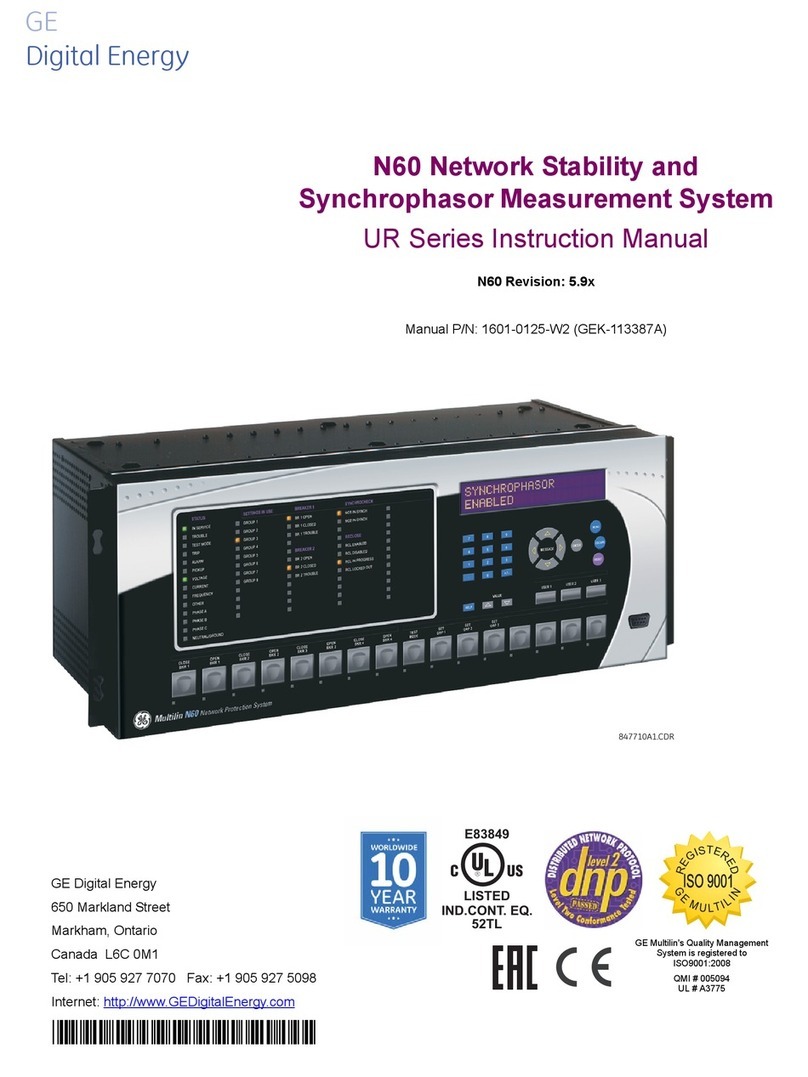
GE MOA 280i User manual

Sievers*Nitric Oxide Analyzer NOA 280i
Operation and
Maintenance Manual
Firmware Version 3.00 and later
6060 Spine Road
Boulder, CO 80301 USA
phone 800.255.6964 • 303.444.2009
fax 303.444.9543 DLM 14291 Rev A
www.geinstruments.com Printed in USA ©2006

GE Analytical Instruments ©2006 DLM 14291 Rev. A
ii
IDENTIFICATION RECORDS
Record the following numbers as they are listed on the identification labels
located on the back panel of the NOA and the front of the vacuum pump.
Analyzer serial no.
Pump serial no.
Warranty Start Date
Date of receipt/Installation
*Trademark of General Electric Company; may be registered in one or more countries.

GE Analytical Instruments ©2006 DLM 14291 Rev. A
iii
PRINTING HISTORY
The information contained in this document may be revised without notice.
Sievers Instruments makes no warranty of any kind with regard to this material.
Sievers Instruments shall not be liable for errors contained herein or for incidental,
or consequential damages in connection with the furnishing, performance or use of
this material.
No part of this document may be photocopied or reproduced without the prior
written consent of Sievers Instruments, Inc.
Initial Printing December 2000
DLM 14290-01 Revision A March 2001
DLM 14291 Revision A May 2006
Printed in USA

GE Analytical Instruments ©2006 DLM 14291 Rev. A
iv
Standard Limited Warranty
GE Analytical Instruments warrants its products (Sievers®, GE Analytical™ and
Leakwise™) against defects in materials and workmanship. GE Analytical
Instruments will, at its option, repair or replace instrument components that prove
to be defective with new or remanufactured components (i.e., equivalent to new).
The warranty set forth is exclusive and no other warranty, whether written or
oral, is expressed or implied.
Warranty Term
The GE Analytical Instruments warranty term is thirteen (13) months ex-works, or
twelve (12) months from installation or start up by GE Analytical Instruments
certified service personnel. In no event shall the standard limited warranty
coverage extend
beyond thirteen (13) months from original shipment date.
Warranty Service
Warranty Service is provided to customers through telephone support (1-800-255-
6964), Monday - Friday, from 8:00 a.m. to 5:00 p.m. (Mountain Time), excluding
all company and legal holidays. Telephone support is provided for troubleshooting
and determination of parts to be shipped from GE Analytical Instruments to the
customer in order to return the product to operation. If telephone support is not
effective, the product may be returned to GE Analytical Instruments for repair or
replacement. In some instances, suitable instruments may be available for short
duration loan or lease.
GE Analytical Instruments warrants that any labor services provided shall conform
to the reasonable standards of technical competency and performance effective at
the time of delivery. All service interventions are to be reviewed and authorized
as correct and complete at the completion of the service by a customer
representative, or designate. GE Analytical Instruments warrants these services for
30 days after the authorization and will correct any qualifying deficiency in labor
provided that the labor service deficiency is exactly related to the originating

GE Analytical Instruments ©2006 DLM 14291 Rev. A
v
event. No other remedy, other than the provision of labor services, may be
applicable.
Repair components (parts and materials), but not consumables, provided in the
course of a repair, or purchased individually, are warranted for 90 days ex-works
for materials and workmanship. In no event will the incorporation of a warranted
repair component into an instrument extend the whole instrument’s warranty
beyond its original term.
Consumables (e.g., dilution standards, verification solutions, and UV lamps, etc.)
are warranted to the extent of their stated shelf life, provided these items are
maintained within the stated environmental limitations. Warranty claims for
consumables and verification standards are limited to the replacement of the
defective items, prorated from the time of claim to the expiration of shelf life.
Shipping
A Repair Authorization Number (RA) must be obtained from the Technical Support
Group before any product can be returned to the factory. GE Analytical
Instruments will pay freight charges, exclusive of any taxes and duties, for
replacement or repaired products shipped to the customer site. Customers shall
pay freight charges, including all taxes and duties, for all products returning to GE
Analytical Instruments. Any product returned to the factory without an RA number
will be returned to the customer.

GE Analytical Instruments ©2006 DLM 14291 Rev. A
vi

GE Analytical Instruments ©2006 DLM 14291 Rev. A
vii
TABLE OF CONTENTS
1. INTRODUCTION...................................................................................................................................... 1-1
SAMPLE INLET SYSTEMS ..................................................................................................................................... 1-5
SAMPLE FLOW CONTROL DEVICE........................................................................................................................ 1-6
OZONE FLOW CONTROL MODULE....................................................................................................................... 1-6
OZONE GENERATOR.......................................................................................................................................... 1-6
CHEMILUMINESCENT REACTION CHAMBER AND OPTICAL FILTER ............................................................................ 1-6
PHOTOMULTIPLIER TUBE AND COOLED HOUSING ................................................................................................. 1-7
VACUUM PUMP AND OZONE DESTRUCTION TRAP................................................................................................. 1-7
ELECTRONICS.................................................................................................................................................... 1-7
ANALOG, PRINTER AND RS-232 OUTPUTS ......................................................................................................... 1-8
EXHALATION PRESSURE TRANSDUCER ................................................................................................................. 1-9
THERMAL MASS FLOW METER ............................................................................................................................ 1-9
2. SPECIFICATIONS..................................................................................................................................... 2-1
3. MENUS AND CONTROL OVERVIEW ..................................................................................................... 3-1
MAIN MENU...................................................................................................................................................... 3-1
STATUS SCREEN................................................................................................................................................ 3-1
ANALYSIS ......................................................................................................................................................... 3-2
MEASUREMENT MENU ........................................................................................................................................ 3-3
MAIN MENU OPTIONS........................................................................................................................................ 3-6
Control..................................................................................................................................................... 3-6
Calibration.............................................................................................................................................. 3-7
Messages.................................................................................................................................................. 3-7
Maintenance............................................................................................................................................ 3-8
TIME-OUT FUNCTION ........................................................................................................................................ 3-8
4. INSTALLATION........................................................................................................................................ 4-1
LOCATION ........................................................................................................................................................ 4-1
POWER REQUIREMENTS ..................................................................................................................................... 4-1
ENVIRONMENTAL CONSIDERATIONS..................................................................................................................... 4-2
TOOLS AND ADDITIONAL SUPPLIES...................................................................................................................... 4-2
Tools......................................................................................................................................................... 4-2
Gases........................................................................................................................................................ 4-2
Data Collection....................................................................................................................................... 4-2
VACUUM PUMP SETUP....................................................................................................................................... 4-4

GE Analytical Instruments ©2006 DLM 14291 Rev. A
viii
Step 1 – Add Oil to the pump...............................................................................................................4-4
Step 2 - Install Pump Inlet Fitting ......................................................................................................4-4
Step 3- Install the Chemical Trap Mounting Bracket.......................................................................4-5
Step 4 - Install the Pump Outlet Fitting............................................................................................ 4-6
Step 5 - Install the Chemical Trap and Vacuum Hoses....................................................................4-6
Step 6 - Connect Power Cord to Vacuum Pump and Turn On Pump Power Switch ....................4-9
CONNECTIONS TO NOA.....................................................................................................................................4-9
Vacuum Pump Power Cord and Vacuum Hose................................................................................... 4-9
Vacuum Test............................................................................................................................................4-9
Gas for Ozone Generator....................................................................................................................4-11
Frit Restrictor....................................................................................................................................... 4-12
Computer, Printer and Analog Signal Connections........................................................................ 4-12
Setting the Clock..................................................................................................................................4-13
CONFIGURATION MENU OPTIONS......................................................................................................................4-14
Com Port................................................................................................................................................4-14
Pressure Units.......................................................................................................................................4-15
SETTING THE CONSUMABLES INSTALLATION DATA..............................................................................................4-16
START-UP.......................................................................................................................................................4-16
5. INSTALLATION AND SETUP: GAS-PHASE MEASUREMENTS............................................................5-1
INSTALLATION OF GAS SAMPLING PACKAGE.........................................................................................................5-1
INSTALLATION OF THERMAL MASS FLOWMETER....................................................................................................5-2
NOA SETUP FOR GAS-PHASE MEASUREMENTS..................................................................................................... 5-4
Exhalation Mode.....................................................................................................................................5-4
Nitric Oxide Mode..................................................................................................................................5-7
6. CALIBRATION..........................................................................................................................................6-1
ZERO GAS CALIBRATION ....................................................................................................................................6-1
Calibration with Zero Air Filter..........................................................................................................6-2
Calibrating with Zero Air Cylinder.....................................................................................................6-2
Zero Gas Calibration Warnings............................................................................................................ 6-4
NO CALIBRATION GAS.......................................................................................................................................6-4
Calibration Gas Warnings.....................................................................................................................6-6
Calculation of Gas Concentration.......................................................................................................6-8
INDEPENDENT CALIBRATION OF PPB AND PPM RANGES ..........................................................................................6-8
ACCURACY OF PPB LEVEL MEASUREMENTS USING PPM LEVEL CALIBRATION ............................................................. 6-9
FLOW/RESPONSE CHARACTERISTICS OF NOA 280I...........................................................................................6-10
CALIBRATION AT LOWER FLOW RATES ..............................................................................................................6-11
GE Analytical Instruments ©2006 DLM 14291 Rev. A
ix
7. ON-LINE EXHALED NITRIC OXIDE ....................................................................................................... 7-1
ASSEMBLY OF THE ACCURATE NO BREATH KIT.................................................................................................... 7-2
CONNECTION OF THERMAL MASS FLOWMETER..................................................................................................... 7-3
CONNECTION OF GAS SAMPLING AND PRESSURE TUBING ...................................................................................... 7-3
INSPIRATORY GAS CONNECTIONS........................................................................................................................ 7-4
Inspiratory Gas Filter............................................................................................................................ 7-4
NOA SETUP..................................................................................................................................................... 7-4
PERFORMING THE MANEUVER............................................................................................................................. 7-5
SELECTION OF NO PLATEAU.............................................................................................................................. 7-6
FLOW/PRESSURE CHARACTERISTICS OF ACCURATE NO RESTRICTORS ................................................................... 7-8
MODELS OF NITRIC OXIDE PRODUCTION IN THE AIRWAYS ..................................................................................... 7-8
CLEANING THE ACCURATE NO BREATH KIT AND FLOWMETER............................................................................... 7-9
Disassemble the Valve........................................................................................................................... 7-9
Prewash the Components................................................................................................................... 7-10
Sterilization.......................................................................................................................................... 7-10
Rinsing.................................................................................................................................................... 7-10
Drying..................................................................................................................................................... 7-10
CHECKING THE INSPIRATORY GAS FILTER.......................................................................................................... 7-11
8. OFF-LINE EXHALED NITRIC OXIDE (BAG SAMPLING) ...................................................................... 8-1
ASSEMBLY OF VITAL CAPACITY BAG COLLECTION KIT........................................................................................... 8-1
ASSEMBLY OF DEADSPACE DISCARD BAG COLLECTION KIT .................................................................................... 8-2
CLEANING THE BAGS......................................................................................................................................... 8-5
COLLECTING THE SAMPLES – VITAL CAPACITY BAG KIT........................................................................................ 8-6
Connecting the bag to the filler......................................................................................................... 8-7
Instructing the Subject and Collecting the Samples ....................................................................... 8-7
Disconnecting the bag from the filler and sealing the bag........................................................... 8-8
COLLECTING THE SAMPLES – DEADSPACE DISCARD BAG KIT.................................................................................. 8-9
Connecting the bag to the filler......................................................................................................... 8-9
Instructing the Subject and Collecting the Samples ..................................................................... 8-10
Disconnecting the bag from the filler and sealing the bag......................................................... 8-11
ANALYZING THE SAMPLES ................................................................................................................................8-11
Analysis Setup....................................................................................................................................... 8-11
NOA SETUP................................................................................................................................................... 8-11
CLEANING THE BAG KITS ................................................................................................................................. 8-13
Vital Capacity Bag Kit......................................................................................................................... 8-13
Deadspace Discard Bag Kit ................................................................................................................. 8-14

GE Analytical Instruments ©2006 DLM 14291 Rev. A
x
FLOW/PRESSURE CHARACTERISTICS OF BAG KITS..............................................................................................8-14
STABILITY OF NO IN MYLAR BAGS....................................................................................................................8-15
OFF-LINE VERSUS ON-LINE EXHALED NO MEASUREMENTS.................................................................................. 8-17
TESTING BAGS FOR PINHOLE LEAKS..................................................................................................................8-17
9. BREATH-BY-BREATH AND CHAMBER SAMPLING FOR EXHALED NITRIC OXIDE..........................9-1
BREATH-BY-BREATH MEASUREMENTS..................................................................................................................9-1
Spontaneously Breathing Subjects......................................................................................................9-1
Ventilated Subjects...............................................................................................................................9-2
NOA SETUP.....................................................................................................................................................9-3
NO/Pressure Offset................................................................................................................................9-3
Humidified Circuits................................................................................................................................9-3
CHAMBER SAMPLING..........................................................................................................................................9-4
NOA SETUP.....................................................................................................................................................9-6
10. NASAL NITRIC OXIDE......................................................................................................................10-1
RECOMMENDED SETUP.....................................................................................................................................10-1
PERFORMING THE MANEUVER........................................................................................................................... 10-2
NOA SETUP...................................................................................................................................................10-3
11. INSTALLATION AND SETUP: LIQUID MEASUREMENTS..............................................................11-1
SUPPLIES........................................................................................................................................................11-1
Gases......................................................................................................................................................11-1
Reagents................................................................................................................................................ 11-1
Lab Equipment......................................................................................................................................11-1
SETUP OF PURGE VESSEL................................................................................................................................. 11-2
Connections of tubing to glassware..................................................................................................11-3
Procedure for Tightening Swagelok Fittings.................................................................................................11-4
DILUTION OF ANTI-FOAMING AGENT................................................................................................................. 11-7
NOA SETUP FOR LIQUID MEASUREMENTS..........................................................................................................11-8
DEPROTEINIZATION PROCEDURES....................................................................................................................11-10
Cold ethanol precipitation...............................................................................................................11-11
Zinc Sulfate/Sodium Hydroxide precipitation..............................................................................11-11
12. MEASUREMENT OF NITRIC OXIDE AND NITRITE IN LIQUID SAMPLES....................................12-1
APPARATUS FOR NITRITE REDUCTION ...............................................................................................................12-1
PREPARATION OF THE NITRITE REDUCING AGENT ..............................................................................................12-2
ADJUSTMENT OF PURGE GAS FLOW RATE .........................................................................................................12-3

GE Analytical Instruments ©2006 DLM 14291 Rev. A
xi
ADJUSTMENT OF LIQUID LEVEL......................................................................................................................... 12-3
Preparation of Stock Solution............................................................................................................ 12-5
Preparation of Dilute Standards....................................................................................................... 12-7
WATER BLANKS .............................................................................................................................................. 12-8
INJECTION TECHNIQUE .................................................................................................................................... 12-9
PREPARATION OF CALIBRATION CURVE ............................................................................................................. 12-9
LINEAR RANGE AND OFF-SCALE PEAKS.............................................................................................................. 12-9
REPEATABILITY ............................................................................................................................................. 12-10
NITRITE CONTAMINATION .............................................................................................................................. 12-10
SAMPLE ANALYSIS ......................................................................................................................................... 12-12
BACKGROUND NITRITE................................................................................................................................... 12-12
REPLACING THE REDUCING AGENT AND OPENING THE PURGE VESSEL ............................................................... 12-13
SEPTUM REPLACEMENT.................................................................................................................................. 12-14
CLEANING THE PURGE VESSEL........................................................................................................................ 12-14
CLEANING OF THE IFD FILTER ....................................................................................................................... 12-16
LONG-TERM MAINTENANCE OF THE PURGE VESSEL AND BUBBLER........................................................................ 12-16
13. MEASUREMENT OF NITRATE, NITRITE AND NITRIC OXIDE IN LIQUID SAMPLES................. 13-1
APPARATUS FOR NITRATE REDUCTION .............................................................................................................. 13-1
Preparation of the Nitrate Reducing Agent.................................................................................... 13-2
Preparation of 1M NaOH..................................................................................................................... 13-2
Startup Procedures for Nitrate Reduction...................................................................................... 13-3
ADJUSTMENT OF PURGE GAS FLOW RATE......................................................................................................... 13-4
LEAK CHECK FOR PURGE VESSEL...................................................................................................................... 13-5
ADJUSTMENT OF LIQUID LEVEL......................................................................................................................... 13-5
Preparation of Stock Solution............................................................................................................ 13-6
Preparation of Dilute Standards....................................................................................................... 13-7
WATER BLANKS .............................................................................................................................................. 13-9
INJECTION TECHNIQUE .................................................................................................................................... 13-9
PREPARATION OF CALIBRATION CURVE ........................................................................................................... 13-10
ANALYSIS OF SAMPLES AND STANDARDS........................................................................................................... 13-10
Serum and Plasma Samples.............................................................................................................. 13-10
NITRATE CONTAMINATION ............................................................................................................................. 13-11
REPLACING THE REDUCING AGENT AND OPENING THE PURGE VESSEL ............................................................... 13-11
OPENING THE GAS BUBBLER .......................................................................................................................... 13-12
SEPTUM REPLACEMENT.................................................................................................................................. 13-13
CLEANING THE PURGE VESSEL........................................................................................................................ 13-13

GE Analytical Instruments ©2006 DLM 14291 Rev. A
xii
CLEANING THE GAS BUBBLER.........................................................................................................................13-15
CLEANING THE BUBBLER TUBING....................................................................................................................13-16
CLEANING OF THE IFD FILTER .......................................................................................................................13-16
Long-term maintenance of the purge vessel and bubbler..........................................................13-17
14. OTHER LIQUID MEASUREMENT TECHNIQUES............................................................................14-1
MEASUREMENT OF NITROSOTHIOLS...................................................................................................................14-1
Cu(I)/Cysteine Reagent.......................................................................................................................14-1
Preparation of Reducing Agent.......................................................................................................................14-1
Preparation of Nitrosothiols Standards..........................................................................................................14-2
Copper(I)/Iodide/Iodine Reagent...................................................................................................... 14-2
Preparation of the Reducing Agent................................................................................................................14-2
Preparation of S-Nitroso-Albumin...................................................................................................................14-3
Treatment of Plasma Samples ........................................................................................................................14-3
MEASUREMENT OF IRON-BOUND NO .................................................................................................................14-3
HEADSPACE MEASUREMENT OF NITRIC OXIDE ....................................................................................................14-4
Apparatus for Headspace Analysis....................................................................................................14-5
Sample Collection................................................................................................................................14-5
Preparation of Standards for Headspace.........................................................................................14-6
DYNAMIC HEADSPACE ANALYSIS........................................................................................................................14-7
15. MAINTENANCE.................................................................................................................................15-1
CHANGING THE VACUUM PUMP OIL ..................................................................................................................15-1
CHANGING THE HOPCALITE TRAP.....................................................................................................................15-4
CLEANING THE CHEMILUMINESCENCE REACTION CELL.........................................................................................15-5
VACUUM TEST .............................................................................................................................................. 15-10
RESET THE CELL CLEANING TIMER..................................................................................................................15-10
LIGHT LEAK TEST..........................................................................................................................................15-10
COOLER MAINTENANCE..................................................................................................................................15-11
TESTING AND CLEANING THE FLOW RESTRICTOR FRIT......................................................................................15-13
GAS SAMPLING PARTICLE FILTER....................................................................................................................15-14
SECURITY .....................................................................................................................................................15-14
16. TROUBLESHOOTING .......................................................................................................................16-1
ERRORS..........................................................................................................................................................16-1
POSSIBLE ERRORS AND REMEDIES...................................................................................................................... 16-2
E 01 – Setup Data Corrupted, Check Before Running ....................................................................16-2
E 02 – Cell Pressure was Above the Limit........................................................................................16-2

GE Analytical Instruments ©2006 DLM 14291 Rev. A
xiii
E 03 – Ozone Supply Pressure was Below the Limit....................................................................... 16-2
E 05 – Cooler Temperature Above the Limit................................................................................... 16-3
WARNINGS ..................................................................................................................................................... 16-3
W 09–Pump Oil Needs to be Replaced.............................................................................................. 16-4
W 10–Pump Oil Needs to be Replaced Soon..................................................................................... 16-4
W 11–Hopcalite Needs to be Replaced............................................................................................. 16-4
W 12–Hopcalite Needs to be Replaced Soon.................................................................................... 16-4
W 13–Reaction Cell Needs to be Cleaned ........................................................................................ 16-4
W 14–Reaction Cell Needs to be Cleaned Soon............................................................................... 16-4
W 15–Cooler Needs to be Serviced.................................................................................................... 16-5
W 16–Cooler Needs to be Serviced Soon.......................................................................................... 16-5
CLEARING THE ERROR AND WARNING STACKS ................................................................................................... 16-6
START-UP TESTS............................................................................................................................................. 16-6
Vacuum Pump....................................................................................................................................... 16-7
Cooler Temp ......................................................................................................................................... 16-7
Supply Pressure.................................................................................................................................... 16-7
PMT Signal............................................................................................................................................. 16-7
TROUBLESHOOTING THE NOA.......................................................................................................................... 16-8
No Power to NOA.................................................................................................................................. 16-9
No Display............................................................................................................................................ 16-10
CELL PRESSURE TOO HIGH OR TOO LOW......................................................................................................... 16-11
GAS SAMPLING PROBLEMS.............................................................................................................................. 16-11
HIGH BACKGROUND NO AFTER CALIBRATION.................................................................................................. 16-12
LIQUID MEASUREMENTS PROBLEMS ................................................................................................................. 16-12
Low Sensitivity.................................................................................................................................................16-12
Leaks in Purge System....................................................................................................................................16-13
Low Conversion for Nitrate............................................................................................................................16-13
Poor Repeatability............................................................................................................................. 16-13
Syringe Problems.............................................................................................................................................16-14
Foaming of theVCl3Reagent..........................................................................................................................16-14
Injection Technique........................................................................................................................................16-14
Contamination .................................................................................................................................................16-14
High background Signal and Rising Baselines................................................................................ 16-15
Ghost Peaks......................................................................................................................................... 16-15

GE Analytical Instruments ©2006 DLM 14291 Rev. A
xiv

GE Analytical Instruments ©2006 DLM 14291 Rev. A
1-1
1. INTRODUCTION
The Model 280i Nitric Oxide Analyzer (NOA™) from Sievers Instruments is a high-
sensitivity detector for measuring nitric oxide based on a gas-phase
chemiluminescent reaction between nitric oxide and ozone:
NO + O3-> NO2*+ O2
NO2*-> NO2+ hν
Emission from electronically excited nitrogen dioxide is in the red and near-
infrared region of the spectrum, and is detected by a thermoelectrically cooled,
red-sensitive photomultiplier tube. The detection limit of the NOA for
measurement of gas-phase NO is ~0.5 part per billion by volume. The detection
limit for measurement of NO and its reaction products in liquid samples is ~ 1
picomole.
In biological systems, nitric oxide is produced from the enzymatic oxidation of
arginine. Three isoforms of the enzyme nitric oxide synthase (NOS) have been
identified in many cell types: endothelial NOS, neuronal NOS, and inducible NOS.
The biological functions of NO include action as a vasodilator, neurotransmitter,
cytotoxic agent, inhibit of platelet aggregation, and activator of smooth muscle
proliferation. Nitric oxide is also present in exhaled breath and may be a useful
marker of airway inflammation.
In solution, nitric oxide reacts with molecular oxygen to form nitrite (NO-2), and
with oxyhemoglobin and superoxide anion (O2- ) to form nitrate (NO- ) . NO also
reacts with thiols to form S-nitroso compounds, amines to form nitrosamines, and
metals to form metal-nitrosyl complexes. In the gas phase, NO reacts with high
concentrations of oxygen to form nitrogen dioxide.

GE Analytical Instruments ©2006 DLM 14291 Rev. A
1-2
UNITED STATES REGULATORY REQUIREMENTS
CAUTION – INVESTIGATIONAL DEVICE:
Limited by United States Law to Investigational use.
EXHALED BREATH AND LIQUID APPLICATIONS:
For Research use Only. Not for Use in Diagnostic Procedures.
SAFETY WARNINGS
WARNING:
High voltage is present in the instrument when power cord is connected. To avoid
potentially dangerous shock, disconnect the power cord before removing the
cover.
WARNING:
This is a safety Class I product provided with a protective earthing ground
incorporated into the power cord. The mains plug shall only be inserted in a socket
outlet provided with a protective earth contact. Any interruption of the protective
conductor, inside or outside the instrument is likely to make the instrument
dangerous. Intentional interruption is prohibited.
WARNING:
This symbol indicates that to comply with European Union Directive 2002/96/EC for
waste electrical and electronic equipment (WEEE), the Analyzer should be disposed of
separately from standard waste.

GE Analytical Instruments ©2006 DLM 14291 Rev. A
1-3
ENGLISH
WARNING:
Any operation requiring access to the inside of the equipment, could result in
injury. To avoid potentially dangerous shock, disconnect from power supply before
opening the equipment.
WARNING:
For continued protection against fire hazard replace fuse with same type and
rating.
WARNING:
This symbol, on the instrument indicates that the user should refer to the
manual for operating instructions.
WARNING:
This is a safety Class I product. It must be wired to a mains supply with a protective
earthing ground incorporated into the power cord. Any interruption of the
protective conductor, inside or outside the equipment, is likely to make the
instrument dangerous. Intentional interruption is prohibited.
WARNING:
If this instrument is used in a manner not specified by Sievers Instruments Inc. USA,
the protection provided by the instrument may be impaired.
WARNING:
Disposal of RAM Card Lithium batteries must follow the local environmental
regulations.
ESPAÑOL
ATENCION:
Cualquier operación que requiera acceso al interior del equipo, puede causar
una lesión. Para evitar peligros potenciales, desconectarlo de la alimentación a
red antes de abrir el equipo.
ATENCION:
Para protección contínua contra el peligro de fuego, sustituir el fusible por uno
del mismo tipo y características.
ATENCION:
Este símbolo, en el instrumento indica que el usuario debería referirse al
manual para instrucciones de funcionamiento.
ATENCION:
Esto es un producto con clase I de seguridad. Debe conectarse a una red que
disponga de tierra protectora en el cable de red. Cualquier interrupción del
conductor protector, dentro o fuera del equipo, puede ser peligroso. Se prohibe
la interrupción intencionada.
ATENCION:
Si este instrumento se usa de una forma no especificada por Sievers
Instruments, Inc., USA, puede desactivarse la protección suministrada por el
instrumento.
ATENCION:
Las pilas de litio de la RAM Card deshechadas deben seguir las regulaciones
medioambientales locales.!
FRANÇAIS
ATTENTION:
Chaque opération à l’intérieur de l’appareil, peut causer du préjudice. Afin
d’éviter un shock qui pourrait être dangereux, disconnectez l’appareil du
réseau avant de l’ouvrir.
ATTENTION:
Afin de protéger l’appareil continuellement contre l’incendie, échangez le
fusible par un fusible du même type et valeur.
ATTENTION:
Le symbol, indique que l’utilisateur doit consulter le manuel
d’instructions.
ATTENTION:
Ceci est un produit de Classe de sécurité I. L’instrument doit être branché
sur l’alimentation secteur par un fil de secteur prévu d’une prise de masse.
Chaque interruption du conducteur protégeant, à l’intérieur ou á l’extérieur
de l’appareil peut rendre l’instrument dangereux. Interruption
intentionnelle est interdite.
ATTENTION:
Si l’instrument n’est pas utilisé suivant les instructions de Sievers
Instruments, Inc., USA, les dispositions de sécurité de l’appareil ne sont plus
valables.
ATTENTION:
Les batteries RAM Card Lithium doivent être déposés suivant les régulations
d’environnement locales.
DEUTSCH
WARNHINWEIS:
Vor dem Öffnen des Gerätes Netzstecker ziehen!
WARNHINWEIS:
Für kontinuierlichen Schutz gegen Brandgefahr dürfen bei
Sicherungswechsel nur Sicherungen der gleichen Stärke verwendet
werden!
WARNHINWEIS:
Dieses, auf dem Gerät weist darauf hin, dab der Anwender zuerst
das entsprechende Kapitel in der Bedienungsanleitung lesen sollte.
WARNHINWEIS:
Dies ist ein Gerät der Sicherheitsklasse I und darf nur mit einem
Netzkabel mit Schutzleiter betrieben werden. Jede Unterbrechung des
Schutzleiters auβerhalb oder innerhalb des Gerätes kann das Gerät
elektrisch gefährlich machen. Absichtliches Unterbrechen des
Schutzleiters ist ausdrücklich verboten.
WARNHINWEIS:
Wenn das Gerät nicht wie durch die Firma Sievers Instruments, Inc.,
USA, vorgeschrieben und im Handbuch beschrieben betrieben wird,
können die im Gerät eingebauten Schutzvorrichtungen beeinträchtigt
werden.
WARNHINWEIS:
Die Entsorgung der Lithium-Batterie in der RAM-Karte darf nur nach den
geltenden Umweltschutzregeln erfolgen.

GE Analytical Instruments ©2006 DLM 14291 Rev. A
1-4
ITALIANO
ATTENZIONE:
Qualsiasi intervento debba essere effettuato sullo strumento può
essere potenzialmente pericoloso a causa della corrente elettrica.
Il cavo di alimentazione deve essere staccato dallo strumento prima
della sua apertura.
ATTENZIONE:
Per la protezione da rischi da incendio in seguito a corto circuito,
sostituire I fusibili di protezione con quelli dello stesso tipo e
caratteristiche.
ATTENZIONE:
Il simbolo, sullo strumento avverte l’utilizzatore di consultare il
Manuale di Istruzioni alla sezione specifica.
ATTENZIONE:
Questo strumento è conforme alle specifiche per I prodotti in Classe I
- Il cavo di alimentazione dalla rete deve essere munito di “terra”.
Qualsiasi interruzione del cavo di terra all’interno ed all’esterno dello
strumento potrebbe risultare pericolòsa. Sono proibite interruzioni
intenzionali.
ATTENZIONE:
Se questo strumento viene utilizzato in maniera non conforme alle
specifiche di Sievers Instruments, Inc. USA, le protezioni di cui esso è
dotato potrebbero essere alterate.
ATTENZIONE:
Le batterie al Litio sulla RAM CARD, quando sono esaurite, devono
essere gettate secondo le regolamentazioni vigenti localmente.
DUTCH
OPGELET:
Iedere handeling binnenin het toestel kan beschadiging
veroorzaken. Om iedere mogelijk gevaarlijke shock te vermijden
moet de aansluiting met het net verbroken worden, vóór het
openen van het toestel.
OPGELET:
Voor een continue bescherming tegen brandgevaar, vervang de
zekering door een zekering van hetzelfde type en waarde.
OPGELET:
Het symbool, geeft aan dat de gebruiker de instructies in de
handleiding moet raadplegen.
OPGELET:
Dit is een produkt van veiligheidsklasse I. Het toestel moet
aangesloten worden op het net via een geaard netsnoer. Bij
onderbreking van de beschermende geleider, aan de binnenzijde
of aan de buitenzijde van het toestel, kan gebruik het toestel
gevaarlijk maken. Opzettelijke onderbreking is verboden.
OPGELET:
Indien het toestel niet gebruikt wordt volgens de richtlijnen van
Sievers Instruments, Inc., USA gelden de veiligheidsvoorzieningen
niet meer.
OPGELET:
RAM kaart Lithium batterijen dienen volgens de lokale
afvalwetgeving verwijderd te worden.

GE Analytical Instruments ©2006 DLM 14291 Rev. A
1-5
Figure 1-1: Schematic of Model 280i Nitric
Oxide Analyzer
The Model 280i NOA is used for measurement of NO in exhaled breath and
measurement of nitrite, nitrate/nitrite and nitrosothiols in biological fluids, cell
culture media, and other liquid samples. A schematic of the 280i NOA is shown in
Figure 1-1 and consists of the following major components:
• Sampling Inlet Systems
• Sample Flow Control Device
• Ozone Flow Control Module
• Ozone Generator
• Chemiluminescence Reaction Chamber and Optical Filter
• Photomultiplier Tube and Cooled Housing
• Vacuum Pump and Chemical Trap
• Front Panel Display
• Four Button Keypad
• PMT Amplifier
• Power Supply
• Analog to Digital Converter
• Microprocessor and Output Electronics
• Analog, Printer, and RS-232 Outputs
• Exhalation Pressure Transducer
• Optional Thermal Mass Flowmeter
Sample Inlet Systems
The NOA 280i has a
complete range of sample
inlet systems for
measurement of NO and its
reaction products including:
• Gas Sampling Kit for
measurement of gas-
phase NO. The kit
includes a Nafion®drier,
0.45 µm particle filter,
PVC sampling lines with
Luer®adapters and a
calibration tee.

GE Analytical Instruments ©2006 DLM 14291 Rev. A
1-6
• Purge vessel for the measurement of NO, nitrite, nitrate and other reaction
products in liquid samples. The purge vessel can also be used for headspace
analysis with a gas-tight syringe.
• Accurate NO™ Exhaled Breath Kit for on-line measurement of exhaled NO using
elevated pressure to close the soft pallet and constant low exhalation flow (30
– 250 mL/s BTPS)
• Bag Collection and Sampling Kit for off-line measurement of exhaled NO using
collection in Mylar® bags.
Sample Flow Control Device
The vacuum pump continuously draws gas into the analyzer at a constant flow
rate. A porous metal frit restrictor sealed in a 1/8" adapter is connected to a
Swagelok®bulkhead union at the rear of the NOA. The standard restrictor provides
a flow rate of ~200 mL/min and restrictors for other flow rates are available from
Sievers Instruments.
Ozone Flow Control Module
The connection for the gas supply for the ozone generator (oxygen or 95% O2/ 5%
CO2) is made using Teflon tubing and a Swagelok bulkhead connector. The gas
must be a regulated supply from an external cylinder, lecture bottle or house
oxygen. The flow rate of gas into the ozone generator (~30 mL/min) is controlled
using a regulator and small diameter tubing restrictors. The regulator and
bulkhead connectors are located on the back of the NOA. The regulator is adjusted
to 6 psi pressure, which is measured by a pressure transducer, and monitored on
the front panel display.
Ozone Generator
An electrostatic ozone generator and high voltage transformer are used to
generate ozone at a concentration of ~2% by volume from oxygen. This large
excess of ozone is sufficient for measurement of NO up to 500 ppm.
Chemiluminescent Reaction Chamber and Optical Filter
Table of contents
Other GE Measuring Instrument manuals
Popular Measuring Instrument manuals by other brands

TELEWAVE
TELEWAVE 44DL user manual

Zenner
Zenner zelsius C5-CMF Installation and operating manual

Leica
Leica iCON PA10 user manual

StoneL
StoneL Quartz QX Series Installation maintenance and operating instructions

Horiba Scientific
Horiba Scientific LAQUAtwin B-74 Series manual

AQUASOL
AQUASOL AB-T-TDS instruction manual