OHTAKE FM-36 Series Guide

QUICHER
NSRI Type
www.ohtake-root.co.jp HP
www.ohtake-root.co.jp
ATTENTION : www.ohtake-root.co.jp is the only web site associated with our company.
We do not have any branches in China.
Operation manual (Maintenance)
自動ネジ供給機
FM-36
Series
Automatic Screw Feeder
FM1MA01M a
・Read these instructions for the proper use of this machine.
・After having read these instructions, keep them in a convenient
place so you or the operator can refer to them whenever necessary.
02M

Note:About the screws stock limit
If too much screws are placed into the storage chamber of the feeder, it may affect the process of screw feeding, or
cause the machine to be overloaded and malfunction.
Please refer to the diagram below and carefully adjust the screw level to be 2 ~3mm below upper edge of the rail.
(When the scoop plates are at the lowest point.)
㹼 㹼
Upper edge of
the rail
Lowest point of the
scoop plates
×Too much screws
○Moderate amount of screws
CAUTION !

– 1–
Install this machine at a level, stable place.
If you install this machine in an unstable location, it may topple or fall, causing personal injury.
Do not operate this machine in places where a ammable or explosive gas exists or the humidity is high.
Using this machine in such places will create a safety hazard.
When shutting down this machine at day’s end or leaving it unused for long periods of time, disconnect its
AC adapter from the power outlet.
Installation
When shutting down this machine at day’s end or leaving it unused for long periods of time
CAUTION
CAUTION
CAUTION
1. Before Use
Thank you very much for purchasing our Automatic Screw Feeder, 『FM-36 series』.
Please check up the accessories supplied with it before using it.
Accessories Operation manual x1 AC adapter x1 Allen wrench x1 Screwdriver x1 Ground wire x1
Before using your product, please read this manual carefully to get best results from the product.
2. Operating Precautions
6. Maintenance----------------------------------------------------------14
7. Replacing Parts------------------------------------------------------15
8. Points to Check Before Requesting Repair Services------17
9. Principal Specifications---------------------------------------------22
10. Warranty Terms-------------------------------------------------------24
11.External dimension---------------------------------------------------25
1. Before Use-----------------------------------------1
2. Operating Precaution----------------------------1
Precautions in Ejecting Screws --------------3
3. Component Names-----------------------------4
4. Identifying the Unit Type------------------------5
5. Getting this machine ready-------------6
Contents

– 2–
Use the accessories AC adapter only.
Do not scratch the rail. Do not apply any oil or grease to the rail.
Use the specied screws only. Avoid using screws to which oil, grease, dirt, or other foreign matter is attached.
When removing screws, exercise care not to apply any undue force or shock to them.
Do not position your ngers or foreign objects in the screw bin, holes, or other open spaces because you may be
injured. Be sure that no inappropriate screws or foreign objects are allowed to enter this machine.
If any abnormality occurs during operation, turn off the power switch and disconnect the AC adapter from the
power outlet.
If you continue to use this machine while it is acting abnormally, a risk of re, electric shock, or personal
injury may be caused. If you encounter any abnormality, contact your local dealer.
When this machine requires maintenace, contact your local dealer.
Rail
AC adapter
Compatible screws
Screw removal precautions
Avoid inserting foreign objects
Abnormalities during operation
Avoid making attempt to repair, disassemble, or modify this machine
CAUTION
CAUTION
CAUTION
CAUTION
When the earth wire is connected, loosen the screw near the mark once.
After attaching the earth wire,tighten the screw again.
Attachment of the earth wire
the bottom of the main body

– 3–
①
③
④
②
Precautions in Ejecting Screws
Please use maximum care in ejecting screws from the Screw bin for changing screw types, replacing the rail and so forth.
◎Screws could fall into the inside of this machine if ejection is mishandled.
◎If this machine is tilted or turned back with screws being accumulated at the unloading port or left on the rail, screws may fall into
the inside of this machine.
◎Unload screws from the unloading port and move all screws from the rail to the screw bin, take them from the chamber.
◎ See the illustrations below for ejecting screws. Use maximum care in ejecting screws from the screw bin not to let them fall into
the inside of this machine.
①Turn off the power switch.
②Unload screws from the unloading lever.
③Tilt the machine backyards,and slide all the screws from the rail back to the screw bin.
Check that no screws are left at the unloading port and on the rail before
ejecting screws from the screw bin.
④ Eject the screws from the screw bin.

– 4–
Rail front-rear
position lock screw
Power switch
LCD panel
Holding plate
(Screw guide 1)
Unloading lever
Screw bin
Screw bin lid
Bit guide assembly
Rail
assembly
Escaper disc
Front cover
Shutter (installed in front
of the passage plate)
Bin scooping
plate
Brush
Timer setting control
DC jack
Bin scooping
plate
Screw bin
Passage plate
Passage window (in the passage
plate)
Passage plate
lock screw
External output
signal line
3. Component Names

– 5–
Identication seal
Identication
seal
4. Identifying the Unit Type
Before using this machine, check to make sure that the nominal diameter of the applied screw meets the unit type.
To identify the unit type, remove the front cover and the rail assembly and look at the labels afxed to the rail assembly and the
Escaper Unit.
This machine can be customized to screws of different sizes by replacing the rail assembly and the Escaper Unit.
This machine ships factory-adjusted to handle pan-head screws.
If this machine requires adjustment to meet the kind of screw to use, make
the following checks and adjustments beforehand:
Brush check and adjustment
Passage plate check and adjustment
Holding plate check and adjustment for height of screw
Rail assembly and Escaper Unit check and adjustment
Type Model number
Screw
nominal
diameter
Exchange
Kit
number
Rail model
number
Escaper Unit
model
number
Passage
plate model
number
FM-3630 3.0 FR30SET FR30 F30 W3630
FM-3635 3.5 FR35SET FR35 F35 W3635
FM-3640 4.0 FR40SET FR40 F40 W3640
FM-3650 5.0 FR50SET FR50 F50 W3650
FM-3660 6.0 FR60SET FR60 F60 W3660
FM-36

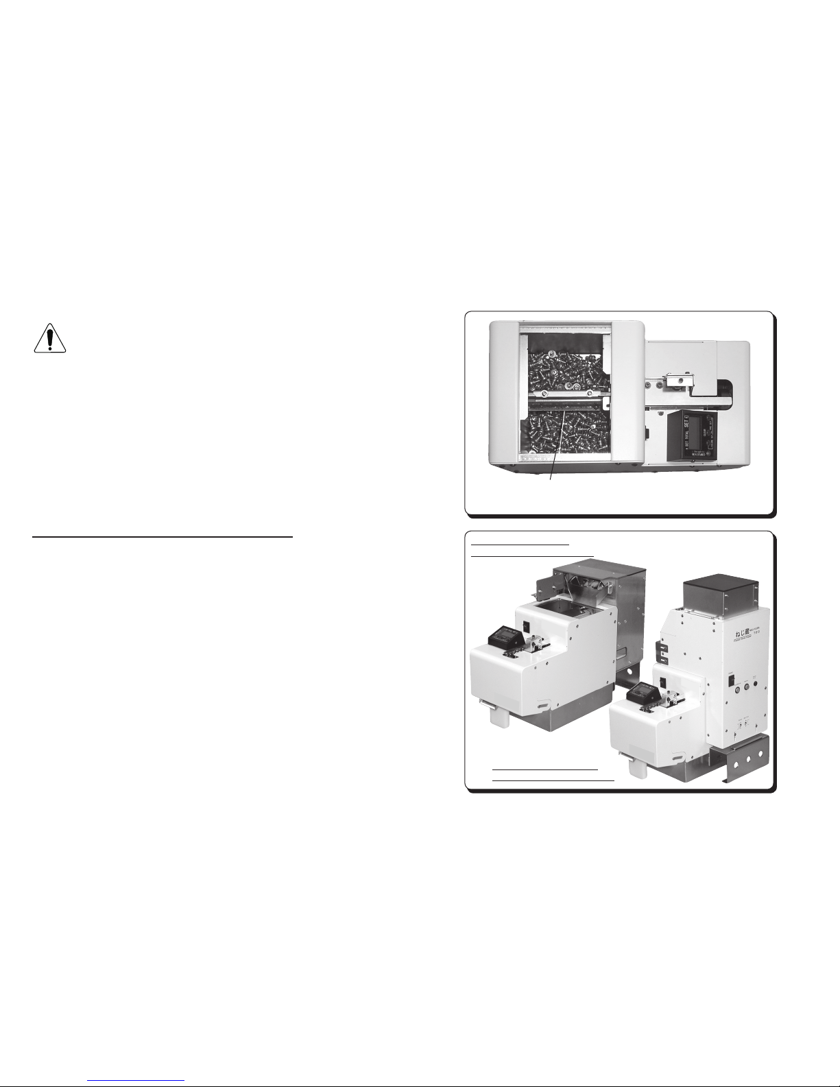
Unit with the oor-type
(NJ-80) NEJIKURA installed
Unit with the tower-type
(T-510) NEJIKURA installed
Do not allow screws cover top surface of the rail groove. (The
screws must be positioned about 2 to 3 mm lower than top
surface of the groove.)
– 6–
5. Getting this machine ready
5.1 Supply of Screws
Loading this machine with too many screws could
adversely affect their alignment and transfer.
The approximate maximum supply of screws is illustrated
in the gure at right. Consult this gure for loading screws.
• Turn the power switch on, then off to move the Bin scooping plate to the
lower position.
• Load screws to a roughly 2 to 3 mm lower than the top surface of the rail
groove. Check to make sure that the top surface of the rail groove is not
covered by the screws.
• Adjust the supply of screws by observing behavior of this machine in
operation.
This machine comes with an overload protection circuit.
The protection circuit trips when the moving parts of this machine are
overloaded, such as when screws being stuck in the moving parts, or too
many screws being put in the screw bin.
Actuation of the overload protection circuit
If the moving parts of this machine are overloaded, the drive motor reverses
for a predetermined period of time and then returns to forwarding. When
the overload imposed on the moving parts of this machine no longer
exists during reversing, the drive motor returns to normal forwarding. If
the overload imposed on the moving parts of this machine persists during
reversing, the drive motor reruns the sequence of reversing, forwarding,
reversing, forwarding and so forth for a predetermined period of time before
it is powered off. The escaper disc continues operating, though.
Thus explained, if the drive motor is powered off, turn off the power switch
and remove the overload imposed on the moving parts of this machine.
For example, if you have put too many screws in the Screw bin, correct the
supply of screws. If screws or any other objects are stuck in the moving
parts of this machine, remove them.
After the overload has been removed, turn on the power switch to put this
machine back into operation (power-on reset).
• A screw stock option, NEJIKURA is available which loads screws
automatically to maintain the supply of screws. Please check with your
dealer if you need this option.
CAUTION

While the LCD panel LED is on, push the unloading lever forward
until it hits the stopper.
Screws will drop onto your palm at the same time.
This machine, when just powered on, behaves differently
depending on the state in which it had been powered off.
This machine won’t start unless you push the unloading lever.
Return your hand to front with care not to drop the screws off
your palm.
The LCD panel LED goes out and this machine restarts.
– 7–
5.2 Unloading Screws
This machine ships factory-adjusted with handle pan-head screws. This
machine should require the following checks and adjustments depending
on the kind of screw to use:
LCD panel setting change
Brush check and adjustment
Passage plate check and adjustment
Holding plate check and adjustment
Rail assembly and Escaper Unit check and adjustment
• When the power switch is turned on, the Bin scooping plate moves up
and down for a predetermined period of time and then stops.
• Push in the unloading lever to start this machine.
• When a preset count of screws has accumulated at the unloading port,
the LED lights up, the buzzer sounds, and this machine halts with a
certain delay.
• Push in the unloading lever to unload the preset (metered) count of
screws and the LED goes out, with this machine restarting.
• If you push the unloading lever before a preset count of screws is
stored, the LED blinks and the buzzer continues sounding. This
machine then starts recounting the preset count of screws after a
period of time.
• Push the unloading lever forward until it hits the stopper. The LCD
panel LED does not go out and this machine does not restart unless
the unloading lever makes full contact with the stopper.

Preset total indicator Preset count indicator
LED indicator Setup buttons
– 8–
5.3 LCD Panel Indicators and Settings
◎LCD Panel Indicators
<Preset count indicator>
• Shows a preset count of screws.
• Decrements each time a screw is delivered to the unloading port.
• Is reset to the preset count when the preset count of screws has
accumulated at the unloading port.
• Blinks while changes are being made to the preset count.
• Each time the preset count of screws has accumulated at the
unloading port, this machine stops. When screws are unloaded from
the unloading port, this machine restarts.
<Preset total indicator>
• Shows the total of preset counts of screws.
• Increments each time a preset count of screws are accumulated at
the unloading port.
• Each time the count of screws has accumulated at the unloading
port, this machine stops. When the screws are unloaded from the
unloading port, this machine restarts.
<LED indicator>
• Lights up each time a preset count of screws has accumulated at the unloading port.
• Blinks when the unloading lever is manipulated while unloading a preset count of screws.
• Blinks while changes are being made to the sound volume.
<Setup buttons>
• Make changes to settings.
• The LCD panel indicators and settings are backed up by internal memory in times of power outages or when the power switch is
turned off. When the power is restored, however, you need to manipulate the unloading lever to start this machine.

<<CLEAR>>
<<PRE SET>>
<<VOLUME SET>>
Resets the preset total
to “0000.”
Sets a preset count.
Sets a sound volume.
– 9–
◎LCD Panel Settings
LCD panel settings can be changed while this machine is shut down after
it has been powered on.
<Clearing the preset total indicator →CLEAR>
• Press the CLEAR button for about 2 seconds, and the buzzer sounds
and you can reset the preset total indicator to “0000.”
<Changing a preset count →PRE SET>
• A preset count can be changed by resetting the preset total indicator to
“0000.”
• Press the right-side PRE SET button to change the rst digit.
Press the left-side PRE SET button to change the second digit.
• Continue pressing a PRE SET button and the buzzer sounds about 2
seconds later and, another 2 seconds later, the buzzer sounds again
with the corresponding digit in the preset count indicator blinking.
• Press the PRE SET button once momentarily while the digit is blinking
to change that digit.
• If you do not press the PRE SET button while the digit is blinking, that
digit is set. The digit is also set if you press the other PRE SET button
while the digit is blinking.
• Take out screws left at the unloading port after a setting change has
been made and return them to the Screw bin.
・A preset count is up to 99.
A preset count is limited by the screw size snd the
capacity of the unloading port .
<Changing the sound volume →VOLUME SET>
• Press the VOLUME SET buttons for about 4 seconds at the same time
and the LED blinks and you can change the sound volume.
• While the LED is blinking, press the right-side button once momentarily
and the sound volume changes from medium to high, no tone, and low,
back to medium and so forth.
• If you do not operate the buttons, the LED stops blinking and the sound
volume then in effect is set.
CAUTION

Check that the passage window is adjusted at such height that
allows the Applied screw to pass barely.
Applied screw
Passage plate
mounting screw
Passage window
(notch in the
passage plate)
Passage plate
Vertical adjustment
Turn the power switch on, then off to keep the brush roughly level.
Brush
Brush height
adjustment screws
Moving the brush by hand, check that the tip of the brush rubs on
the head of the Applied screw placed in the rail groove.
Brush
Passage
plate
Brush height
adjustment
screws
Brush assembly
mounting screw
Applied screw
– 10 –
5.4 Brush Check and Adjustment
Turn off the power switch before performing check
and adjustment work.
Put a screw to use in the screw bin and turn the power switch on, then off
to place the screw into the rail groove.
• Turn the power switch on, then off to keep the brush roughly level as
shown at right.
• Check that the tip of the brush swipes above the head of the applied
screws placed in the rail groove.
• The alignment and transfer of screws would be adversely affected if the
brush is positioned too high or too low.
• If the brush requires adjustment, loose the brush height adjustment
screws.
• If the front of the plastic part of the brush hits the passage plate, loosen
the brush assembly mounting screw and adjust its longitudinal position.
• Run this machine to check that the brush works correctly.
5.5 Passage Plate Check and Adjustment
Turn off the power switch before performing check
and adjustment work.
• Check that the passage window is adjusted at such height that allows
the applied screw to pass barely.
• Too low a passage window would not allow screws to pass, and
too high a passage window would make screws more liable to stop
delivery.
• If the passage pate requires adjustment, loose the passage plate
mounting screw.
• When the adjustment is complete, verify correct operations.
CAUTION
CAUTION

- 11 -
株式会社 大武・ルート工業
図
番
A3
承
認
検
図
製
図
設
計
変更番号 年月日 変 更 記 事 承認 変更者
×
作 成 年 月 日
作業内容 製品名
(部品名)
_15s
ビットガイドAssy上下調整ネジ
ネジ押え板
ビットガイドAssy固定ネジ
ネジ押え板固定ネジ
切出し円板
約1mm
H1
H2
切出し円板
ネジ押え板R部分
ネジ押え板 使用ネジ
約1mm
H1
H2
株式会社 大武・ルート工業
図
番
A3
承
認
検
図
製
図
設
計
変更番号 年月日 変 更 記 事 承認 変更者
×
作 成 年 月 日
作業内容 製品名
(部品名)
_15s
ビットガイドAssy上下調整ネジ
ネジ押え板
ビットガイドAssy固定ネジ
ネジ押え板固定ネジ
切出し円板
約1mm
H1
H2
切出し円板
ネジ押え板R部分
ネジ押え板 使用ネジ
約1mm
H1
H2
5.6 Holding Plate Check and Adjustment
Check the Holding plate position.
• Without a clearance between the head of the applied screw in the
rail groove and the Holding plate, screws could be stuck. Too large
a clearance could cause screws to overlap or cause them to pop out
and fall into the machine.
• If the Holding plate requires adjustment, please do so by the
following;
(1)Vertical adjustment of the Holding plate
• Loosen the bit guide assembly setscrew and turn the bit guide
assembly vertical adjustment screw.
・Make adjustments for a clearance of about 1 mm between the head
of the applied screw.
• Clamp the bit guide assembly setscrew.When the adjustment is
complete, verify correct operations.
・Screws on the rail are delivered smoothly.
・Screws do not fall out from the rail.
(2)Adjustments for a clearance between Escaper disk and Extended
part of Holding plate
・Loosen the Holding plate setscrews.
・
Move the Holding plate to right and left, so that clearance H1 and H2
of the right gure become about the same.
・ Fusten the Holding plate setscrews .When the adjustment is
complete, verify correct operations and no troubles occur.
・When the applied screws are put on the groove of the escaper disk ,
turned the escaper disk to the right side by hand
・
A screw does not get stuck by Holding plate when the escaper
disk turns.
・A screw does not y out from the escaper disk.
Holding plate setscrews
Holding plate
Bit guide assembly setscrew
Bit guide assembly vertical adjustment screw
Escaper disk
Escaper disk
Applied screw
Holding plate
Extended part of
Holding plate
About 1mm

Short
Long
– 12 –
5.7 Timer Check and Adjustment
The applied screw transfer speed varies depending on the screw type.
A longer timer interval setting is recommended for screws with a lower
transfer speed, and a shorter timer interval setting is recommended for
screws with a faster transfer speed.
• This machine is designed to halt screw transfer with a certain delay after
a certain count of screws has accumulated at the unloading port. This
delay can be adjusted with the timer.
• A Timer setting control screw is found in the rear of this machine as
shown at right.
• Turn the trimmer clockwise when this machine is viewed from the rear to
decrease the interval or counterclockwise to lengthen the interval.
• Adjust the trimmer within the range of its rotation, without using undue
force.
• Use the provided screwdriver for adjusting the trimmer.
• Set an appropriate timer interval by verifying a correct this machine
operation on applied screws.

– 13 –
Signal
line
Cover rear
Grommet
Signal line
Grommet
Give one or more turns to the signal
line around the coaching clip so it
can be safely pulled from outside.
Mounting screw
(M2.6)
Total four screws,
including screws on
the opposite side
machine board
External
Purple
Gray
5.8 External Output Signal Line
This machine has an external output signal line, allowing for external
generation of a signal synchronized with the timing at which the LCD panel
LED lights up, as an open collector output. Use this output to connect an
indicator, buzzer or the like externally.
The signal line is housed inside this machine. To use the signal line, lead
it outside through the grommet in the rear of the cover.
㼀㼔㼕㼟㻌㼟㼕㼓㼚㼍㼘㻌㼣㼕㼞㼑㻌㼟㼔㼍㼘㼘㻌㼎㼑㻌㼡㼟㼑㼐㻌㼣㼕㼠㼔㻌㼍㼡㼠㼛㼙㼍㼠㼕㼏㻌㼍㼟㼟㼑㼙㼎㼘㼥㻌㼙㼍㼏㼔㼕㼚㼑㼟
㼛㼞㻌㼑㼤㼠㼑㼞㼚㼍㼘㻌㼟㼏㼞㼑㼣㻌㼏㼛㼡㼚㼠㼑㼞㼟㻚
㼇㻲㼡㼚㼏㼠㼕㼛㼚㼉㻦
㻌㻌㻿㼏㼞㼑㼣㻌㼜㼞㼑㼟㼑㼚㼠㻌㻌㻌㻌㻌㻌㻌㻌㻌㻌㻌㻌㻌㻌㻦㻌㼟㼕㼓㼚㼍㼘㻌㼔㼕㼓㼔㻌㻔㻻㻺㻕
㻌㻌㻵㼚㼏㼛㼙㼕㼚㼓㻌㼏㼡㼞㼞㼑㼚㼠㻌㻌㻌㻌㻌㻌㻌㻌㻌㻌㻌㻦㻌㼟㼔㼍㼘㼘㻌㼎㼑㻌㼘㼕㼙㼕㼠㼑㼐㻌㼠㼛㻌㼘㼑㼟㼟㻌㼠㼔㼍㼚㻌㻝㻜㻜㼙㻭
㻌㻌㻌㻖㻯㻭㼁㼀㻵㻻㻺㻦㻌㻭㼐㼐㼕㼠㼕㼛㼚㼍㼘㻌㼞㼑㼟㼕㼟㼠㼛㼞㻌㼕㼟㻌㼞㼑㼝㼡㼕㼞㼑㼐㻌㼛㼚
㻌㻌㻌㻌㻌㻌㻌㻌㻌㻌㻌㻌㻌㻌㻌㻌㻌㻌㻌㻌㻌㻌㻌㻌㻌㼑㼤㼠㼑㼞㼚㼍㼘㻌㼏㼕㼞㼏㼡㼕㼠㻌㼒㼛㼞㻌㼞㼑㼓㼡㼘㼍㼠㼕㼚㼓㻌㼏㼡㼞㼞㼑㼚㼠㻌㻖
㼇㻯㼍㼜㼍㼏㼕㼠㼥㼉㻦
㻌㻌㻹㼍㼤㻌㻰㻯㻌㼏㼡㼞㼞㼑㼚㼠㻌㻌㻌㻌㻌㻌㻌㻌㻌㻌㻌㻦㻌㻝㻜㻜㼙㻭
㻌㻌㻱㼤㼠㼑㼞㼚㼍㼘㻌㼟㼡㼜㼜㼘㼥㻌㼢㼛㼘㼠㼍㼓㼑㻌㻦㻌㻡㻌㼠㼛㻌㻞㻠㼂㻰㻯㻌㻌㻔㻹㼍㼤㻦㻌㻞㻣㼂㻰㻯㻕
㼇㻯㼍㼡㼠㼕㼛㼚㼉㻦
㻌㻌㻼㼘㼑㼍㼟㼑㻌㼗㼑㼑㼜㻌㼠㼔㼑㻌㼘㼑㼚㼓㼠㼔㻌㼛㼒㻌㼛㼡㼠㼜㼡㼠㻌㼟㼕㼓㼚㼍㼘㻌㼣㼕㼞㼑㻌㼘㼑㼟㼟㻌㼠㼔㼍㼚㻌㻟㼙㻧
㻖㻌㼀㼔㼑㻌㼜㼡㼞㼜㼘㼑㻌㼣㼕㼞㼑㻌㼒㼡㼚㼏㼠㼕㼛㼚㼟㻌㼍㼟㻌㼟㼕㼓㼚㼍㼘㻌㼛㼡㼠㼜㼡㼠㻌㼔㼕㼓㼔㻌㻔㻯㼛㼘㼘㼑㼏㼠㼛㼞㻌㼑㼚㼐㻕㻘
㻌㻌㼣㼕㼠㼔㻌㼠㼔㼑㻌㼓㼞㼍㼥㻌㼣㼕㼞㼑㻌㼍㼟㻌㼏㼛㼙㼙㼛㼚㻌㻔㻱㼙㼕㼠㼠㼑㼞㻌㼑㼚㼐㻕
エスケーパネジ取出し部にネジが
有るか 無いか の信号を取出せます。
ネジ締めロボット、 汎用カウンター等との接続にご利用ください。
[仕様 ] ネジ検出時 ON
吸込み電流 max 100mA 以下になるように
固定抵抗等で電流制限をかけてください。
[定格 ] 直流電流 max 100mA
外部印加電圧 5~24VDC (max 27VDC)
[注意 ] 信号線の長さは 3m 以内としてください。
C側 (信号線紫色) を高電位、
E側 (信号線灰色) を低電位にしてご使用ください。
紫色の線ーーー>信号線 (ネジが無いとき OFF)
(ネジがあるとき ON)
灰色の線ーーー>コモン線
CN10
紫
灰
接続例
Example
Inside
Outside
Purple
Gray
High voltage
Low voltage
When LED is lighting

– 14 –
Front cover
Remove two front cover mounting screws,
including one on the opposite side
Loosen the Rail front-rear position
lock screw and pull out the rail.
Clean the rail groove
Escaper Unit
mounting screws
Escaper Unit
Adjust the positions of the rail
groove and the escaper disc
groove.
In the photo, the Holding plate
is removed, but adjustments
may also be carried out
with the Holding plate being
moved upward.
6. Maintenance
Turn off the power switch before performing check and
adjustment work.
Eject all applied screws from within this machine before
proceeding with maintenance work.
A dirty rail groove could slow down the applied screw transfer speed. If the
rail groove is found noticeably soiled, wipe it off with a thin cloth moistened
with alcohol.
If the rail groove is difcult to clean, the rail can be detached from this
machine for cleaning. Before detaching the rail from this machine, turn off
the power switch and remove the screws from the Screw bin (to prevent
screws from falling into the machine).
Remove two front cover mounting screws and move the front cover.
Remove the Escaper Unit mounting screw and then detach the escaper
disc.
(See 7.3, “Replacing the Escaper Unit.”
Then, loosen the Rail front-rear position lock screw and pull out the rail
assembly to front.
The rail should require replacement if its rail groove is soiled or damaged
to impair its function.
If the rail assembly has been removed from this machine, it is necessary to
make positional adjustments with the tip of the rail and the escaper disc.
• Align the groove rail and the groove in the escaper disc with each other.
• Mount the Escaper Unit to keep the top surface of the groove in the
escaper disc lower than the top surface of the rail groove.
• Turn on this machine and then make adjustments with the longitudinal
position of the rail so its tip will not hit the escaper disc when the rail
vibrates.
CAUTION

Brush assembly
mounting screw
Brush assembly
Must not hit
Passage plate
Passage plate lock screw
– 15 –
7. Replacing Parts
7.1 Replacing the Brush
Turn off the power switch before performing check and
adjustment work.
If the tip of the brush has worn to such degree that the brush can no
longer brush away screws in an abnormal posture, replace it with a new
brush.
• Turn this machine power switch on, then off to position the brush as
shown at top-right and then remove the brush assembly. (Have the
brush assembly positioned to ease the work of removing the mounting
screw.)
• The brush assembly can be disassembled as shown at right.
• To reassemble the brush assembly, reverse the removal procedure.
• When the reassembly is completed, check to make sure that the front of
the plastic part of the brush won’t hit the passage plate when the brush
assembly operates. A ideally clearance of 0 is recommended.
• For adjustment instructions, see 5.4, “Brush Check and Adjustment.”
7.2 Replacing the Passage Plate
Turn off the power switch before performing check and
adjustment work.
When using screws of different nominal diameters, replace the passage
plates for both the rail assembly and the Escaper Unit.
• Remove the Passage plate lock screw and then remove the passage
plate.
• Keep the setscrew in a safe place.
• Install the passage plate in position with reference to the drafts on its
both sides.
• After the adjustment, the passage pate requires adjustment to meet the
kind of screw to use.
For adjustment instructions, see 5.5, “Passage Plate Check and
Adjustment.”
Parts number :NJ02005a #02
Brush bracket 1
Brush bracket 2 Brush
Hex socket head
machine screw
M2.6x10
Spring washer
M2.6
Washer
M2.6
Brush assembly exploded view
CAUTION
CAUTION

– 16 –
Adjust the positions of the rail groove
and the escaper disc groove.
In the photo, the Holding plate is
removed, but adjustments may also be
carried out with the Holding plate being
moved upward.
Remove two mounting
screws, including one on
the opposite side
Remove the
Escaper Unit
mounting screws
Slide the front cover to a
slanted position and then it
downward
Remove the motor
connector
Remove the sensor
connector
Loosen the Rail front-
rear position lock screw
and pull out the rail
7.3 Replacing the Escaper Unit
Turn off the power switch before performing check and
adjustment work.
When using screws of different nominal diameters,
replace the passage paltes for both the rail assembly
and the Escaper Unit.
• Remove two front cover mounting screws.
• Slide the front cover along the skewed groove on the side to a slanted
position. Then,open the front cover downward.
• Remove the motor connector and the sensor connector.
• Remove the Escaper Unit mounting screw and then remove the Escaper
Unit.
• To reassemble the Escaper Unit, reverse the removal procedure.
• The Escaper Unit requires positional adjustments in relation to the rail
groove. See the instructions below.
7.4 Replacing the Rail Assembly
Turn off the power switch before performing check and
adjustment work.
Eject all applied screws from inside this machine before
proceeding with replacement work.
The rail assembly in this machine is easy to replace. The rail should
require replacement if its rail groove is soiled or damaged to impair its
performance.
When using screws of different nominal diameters, replace the passage
plates for both the rail assembly and the Escaper Unit.
The rail assembly can be removed after the Escaper Unit has been
removed.
• Loosen the Rail front-rear position lock screw and pull out the rail
assembly to front.
• At reassembly, it is necessary to make positional adjustments with the tip
of the rail and the escaper disc.
• Align the groove rail and the groove in the escaper disc with each other.
• Mount the Escaper Unit to keep the top surface of the groove in the
escaper disc lower than the top surface of the rail groove.
• Turn on this machine and then make adjustments with the longitudinal
position of the rail so its tip will not hit the escaper disc when the rail
vibrates.
CAUTION
CAUTION

– 17 –
Symptom Cause Action
8-1
This machine won’t start when
the power switch is turned on
8-2
Screws won’t come owing
• Power is not connected.
• Screws that have accumulated at the
unloading port have not been unloaded for a
certain period of time.
• The unloading lever has not been pressed
rmly.
• Too many screws have been put in the
Screw bin (overload protective circuit
tripped).
• Foreign matters (such as screws) have
entered the inside of this machine (overload
protective circuit tripped).
• AC adapter failure
• Screws having a larger nominal diameter
than specied have been loaded, or screws
of different nominal diameters were present.
• The supply of screws in the Screw bin has
used up.
• Check that AC adapter power connection.
• Manipulate the unloading lever to unload screws
from the unloading port.
• Press the unloading lever rmly until it hits the
stopper (LCD panel LED going out).
• Adjust the Timer setting control screw.
• Adujst amount of screws in the Screw bin.
• Remove the foreign matters.
• Contact your service agent or dealer.
• Use screws of the specied nominal diameter.
• Remove the screws of the different nominal
diameters.
• Correct the supply of screws in the Screw bin.
• Use of the NEJIKURA option is recommended.
8. Points to Check Before Requesting Repair Services
Turn the power switch off before troubleshooting this machine.
CAUTION

– 18 –
Symptom Cause Action
8-2
Screws won’t come owing • The brush cannot brush away screws in an
abnormal posture.
• The shank of a screw has entered the
passage window.
• Screws have been stopped in an unusual
posture halfway in the rail.
• The rail can't move longitudinally (due to
screws stuck in rail gaps, for example).
• Improperly adjusted timer setting control
screw
• Adjust the brush.
Adjust the passage plate.
Putting an appropriate supply of screws in the
Screw bin could x the problem.
• Remove unusual screws and then adjust the
passage plate.
• Remove the screws in an unusual posture.
Follow the instruction given below to remove
screws. In doing so, be careful not to scratch the
rail groove and other components.
Loosen the bit guide assembly setscrew.
Move up the Holding plate.
Remove the screws in an unusual posture.
Then, adjust the Holding plate position.
• Remove the screws stuck in gaps.
If no screws are stuck, contact our service to
resolve the problem.
• Adjust the timer setting control screw again.
Other manuals for FM-36 Series
1
This manual suits for next models
5
Table of contents
Popular Tools manuals by other brands

BGS technic
BGS technic 62607 instruction manual

Scissorsafe
Scissorsafe SCS003 User instructions

Stakon
Stakon COMFORT CRIMP SHURE STAKE ERG4 Instructions for use

Alpha Professional Tools
Alpha Professional Tools Alpha BAB3GRD instruction manual

Ryobi
Ryobi EHT150RG Owner's operating manual

EIBENSTOCK
EIBENSTOCK EBM 352/3 Original instructions