OK International TS350 User manual

Techcon Systems
TS350 / 355
Precision Dispensers
User Guide
English, Simplified Chinese, Traditional Chinese and Korean Version
Copyright © OK International
TS350/TS355
精密点胶机
用户指南
TS350/355
精密點膠機
使用者指南
TS350/355
정밀 디스펜서
사용설명서
2
CONTENTS
Page Number
1Safety....................................................................................................2 - 3
2Symbol Definitions...............................................................................3
3Specifications .......................................................................................3
4Features ................................................................................................4
5Connecting the Unit..............................................................................5
6Setup Instructions.................................................................................5 - 6
7 Troubleshooting ...................................................................................7
8 Maintenance .........................................................................................8
9 Spare Parts and Accessories .................................................................8
10 Warranty...............................................................................................8
11 I/O Configuration and End of Cycle Switch ........................................9
1SAFETY
1.1 Intended Use:
WARNING: Use of this equipment in ways other than those described in this User
Guide may result in injury to persons or damage to property. Use this equipment
only as described in this User Guide.
OK International cannot be responsible for injuries or damages resulting from
unintended applications of its equipment. Unintended uses may result form taking
the following actions:
•Making changes to equipment that has not been recommended in the User
Guide
•Using incompatible or damaged replacement parts
•Using unapproved accessories or auxiliary equipment
1.2 Safety Precautions:
•Do not operate this unit in excess of maximum ratings/settings
•Always wear appropriate personal protective clothing or apparel
•Use only the following power adaptor models: PSA15R-240P(ZJ) or
PW118RA2403B01, PW118RA2403H01, PW118RA2403M01,
PW118RA2403G01
•Care must be taken to prevent the ingress of corrosive or flammable fluid back
into the unit. If corrosive or flammable fluids are used, an inline filter (881-
000-000) must be installed on the dispenser to help prevent the fluids from
being sucked back into the unit
•The fluid being dispensed may be toxic and/or hazardous. Refer to Material
Safety Data Sheet for proper handling and safety precautions
•If a piston is not used with the barrel, an inline filter (881-000-000) must be
installed on the receiver head to help prevent fluids from being sucked back
into the unit. Also do not overfill the barrel and to lay the barrel on its side
•Do not smoke or use open flame when flammable materials are being dispensed
Call for Details (800)401-1441

3
•This equipment is for indoor use only
2SYMBOL DEFINITIONS
Symbol Definition
Power On/Off
Cycle Mode
Timer
Vacuum
Pressure
3SPECIFICATIONS
Size 152mm X 165mm X 178mm
(6” X 6.5” X 7”)
Weight 1.2 kg (2.6lbs)
Input Voltage 24VDC
Rated Power 10W
Air Input 100 psi (6.9 bar) Max.
Pollution Degree II
Installation Category I
Indoor Use Altitude up to 2,000m (6,562ft)
Operating Temperature 0˚C to 50˚C (32˚F to 122˚F)
Storage Temperature -10˚C to 60˚C (14˚F to 140˚F)
Max. Relative Humidity 80% for temperature up to 31˚C (87.8˚F)
Decreasing linearly to 50% relative
humility at 40˚C (104˚F)
Air Output TS350 = 0-100 psi (0-6.9 bar)
TS355 = 0-15 psi (0-1.03 bar)
Vacuum 406mm (16”) of Hg
Timer 0.008-60.000 seconds
Cycle Mode Timed, Interrupt, Teach, Purge
Timing Repeat Tolerance +/- 0.001%
Cycle Rate 1,200 cycles/min.
LCD 20 X 4 display segments
4
4FEATURES
Figure 1.0
Items Description
1 Power Button
2 Mode Button
3 Reset Button
4 Display
5 Air Pressure Regulator
6 Pulsed Air Outlet
7 Vacuum Control
8 Setup Control Knob
9 Foot Switch Receptacle
10 Receiver Head air hose holder
11 Power Receptacle
12 I/O Connection
13 Exhaust Port
14 Accessory Air Outlet
15 Air Inlet
16 Cord Lock
3
7
8
6
5
2
1
4
9
15
16 13
10
12
11
14

5
B
1
2
3
4
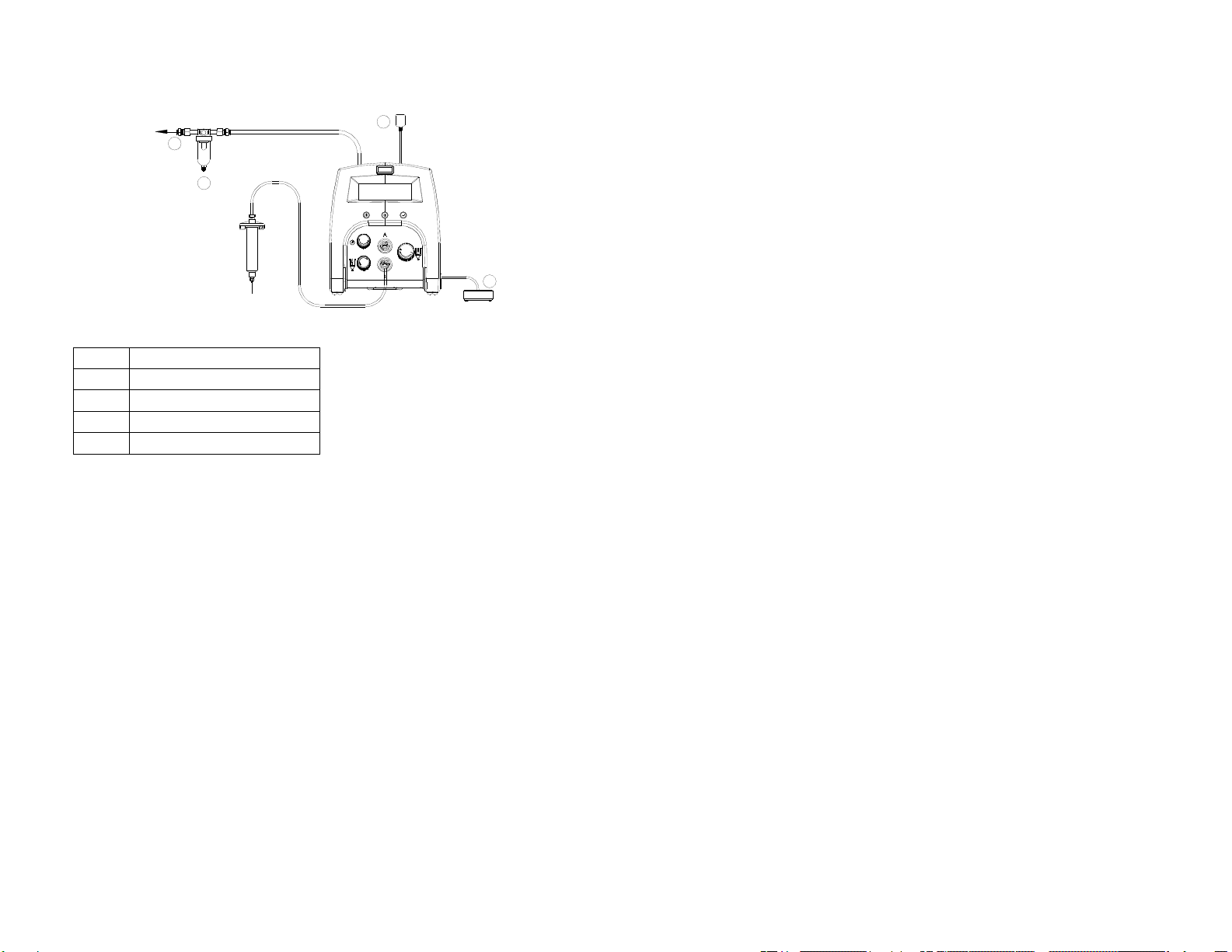
5CONNECTING THE UNIT
CAUTION: A 5-micron filter TSD800-6, not included, must be installed with the unit
to ensure proper air filtration.
Figure 2.0
6SETUP INSTRUCTIONS
Refer to Figure 1.0
6.1 Manual/Purge Dispense Cycle Setting:
1. Turn on the unit by pressing the Power button (1)
2. Press the Mode button (2) until “PURGE” appears on the Display.
3. Turn up the air pressure by rotating the Air pressure regulator knob (5)
until the desired pressure is indicated on the Display
4. After filling the barrel or using pre-packaged adhesive, attach syringe to
receiver head assembly. Make certain that the syringe locks into place
5. Connect the plug end of the receiver head assembly to one of the air
dispense outlet (6).
6. If vacuum “suck back” is needed, rotate the Vacuum regulator (7) counter
clockwise until the desired vacuum pressure is indicated on the Display
7. Press and hold the Foot switch to activate dispensed cycle. (The
Manual/Purge Mode is now activated)
6.2 Automatic Dispense Cycle Setting
6.2.1 Program selection
1. Press the reset button (3) until “P:” is flashing
2. Rotate the Setup Control Knob (8) to select desired program
6.2.2 Time setting
1. Press the Mode button (2) to select “TIMED” mode
2. Press and release the reset button (3) until the colon cursor (:) in the
“TIME:” is flashing.
3. Rotate the Setup control knob (8) to set the desired dispense time
4. Depress Foot switch to activate timed dispensed cycle
Items Description
1 To Air Source
2 Air Filter (Not Included)
3 Power Adapter
4 Foot Switch
6
6.3 Teach Mode Setting
In the teach mode, the unit will accumulate time as long as the foot switch
is depressed. This is helpful in determining dispense time required when
dispense output is unknown.
1. Press the Mode button (2) to select “TEACH” mode.
2. Press and release the reset button (3) until the dispense time = 0.000S
3. Press and hold down Foot switch. Dispense time will accumulate
during this time.
4. Release Foot switch when proper amount of fluid is dispensed.
5. Press the Mode button (2) to switch the “TIMED” mode.
6. The dispenser is now set to repeat this time cycle.
6.4 Multiple Shots Setting:
Up to ten separate individual or sequenced shots can be stored in the
TS350/TS355.
1. Follow steps in section “6.2 Automatic Dispense Cycle Setting” to
set dispense time in desired programs.
2. Press both the Reset button (3) and the Power button (1)
simultaneously to activate sequence program mode.
3. Rotate the Setup Control knob to select total number of program to be
dispensed in sequence
4. Press both the Reset button (3) and Power button (1) to exit Multiple
Shots mode.
6.5 Cycle Counter
The cycle counter records the numbers of automatic dispense cycle being
activated. Up to 65,535 cycles can be recorded. This number is shown at
the lower right hand corner of the LCD. To reset the counter, press and
hold the Reset button (3) and the Mode button (2) simultaneously until the
counter shows “0”.
6.6 Change Pressure and Vacuum Unit Display
1. Press and release the reset button (3) until the colon cursor (:) in the
“PRESSURE:” or “VACUUM:” is flashing
2. Rotate the Setup control knob (8) to select desired unit display

7
7TROUBLESHOOTING
PROBLEM POSSIBLE CAUSE CORRECTION
•LCD does not
light
•No power input
•
Check power cord
connections
•Turn on power
•System will not
actuate
•Foot switch not
plugged in or
improperly plugged
in
•Defective foot
switch
•Broken wire or loose
connection inside
unit
•Defective solenoid
•Defective PC board
•
Check foot switch
connection
•Foot switch needs to be
repaired or replaced
•Unplug power cord and
disconnect air supply.
Remove cover and
check for broken wires
or loose connections
•Replace solenoid
•Replace PC board
•System will not
pressurize
•Insufficient air
pressure
•Air hoses not
plugged in
•Regulator defective
•
Increase air supply
pressure
•Check connection
•Replace regulator
•System will not
pull vacuum
•Vacuum setting is
too low
•Defective solenoid
•Defective vacuum
venturi
•Defective vacuum
needle valve
•
Increase vacuum setting
•Replace solenoid valve
•Replace venture
•Replace needle valve
•Inconsistent
dispensing
•Air bubbles in
adhesive
•Dispense time is too
low
•Dispense needle
started to clog
•
Reduce vacuum setting
•Increase dispensing
time
•Replace needle
8
8MAINTENANCE
The dispenser is designed and built to be relatively maintenance free. To assure
trouble free operation, the following recommendations should be followed:
1. Make certain air supply is clean and dry.
2. Avoid turning barrels upside down or laying barrel so that material may
run through air line to internal components.
3. Avoid connecting the unit to excessive moisture or solvent saturation.
4. Avoid connecting air supply exceeding 100 psi (6.9 bar) for the TS350
and 15 psi (1.03 bar) for the TS355.
5. Use only Amyl Alcohol to clean outside surface of the main housing.
6. Use only soft cloth to clean the LCD.
9SPARE PARTS AND ACCESSORIES
For TS3xx/2xx spare parts and accessories information, please visit the TS3xx/2xx
User Guide webpage at http://www.techconsystems.com
10 LIMITED WARRANTY
OK International warrants this product to the original purchaser for a period of one
(1) year from date of purchase to be free from material and workmanship defects but
not normal wear-and-tear, abuse and faulty installation. Defective product or
subassembly and components under warranty will be repaired or replaced (at OK
International's option) free of charge. Customer with defective product under
warranty must contact the nearest OK International office or distributor to secure a
return authorization prior to shipping the product to the assigned OK International
authorized service center. For nearest OK International office or distributor contact
information, please visit www.techconsystems.com. OK International reserves the
right to make engineering product changes without notice.

9
11 I/O Configuration and End of Cycle Switch
During a dispense cycle, an open collector circuit closes and remains closed while
the valve is dispensing.Pin 3 and 4 can be as feedback signal to synchronize with
other devices. Power from an external source is allowed to pass through the circuit
to operate a 5 to 24 VDC load. Power consumption must not exceed 250 mA. The
load could be a relay, solenoid, counter, LED, or any device that will operate within
a 5 to 24 VDC range and a maximum of 250 mA.
Note:
During the dispense cycle, pin 3 will be grounded. Please make sure the
external device (your machine that controls the dispenser/controller) has the
same ground as the TS350/355 controller.
Pin 7, 8, and 9 = Available
Chasis Ground
To initiate a dispense cycle with
contact closure
When low pressure alarm is triggered, Pin 4 is grounded (-)
When low pressure alarm is turned off,
Pin 4 is not connected (opened)
End of Cycle Feedback
During dispensing cycle, Pin 3 is grounded (-)
End of dispensing cycle,
Pin 3 is not connected (opened)
To initiate a dispense cycle with voltage
Pin 1 (+)
Pin 2 (-)
Pin 3
Pin 4
Pin 5
Pin 6
Pin 5
2
目录
页码
1安全信息.....................................................................................2 - 3
2符号定义.....................................................................................3
3规格说明.....................................................................................3
4特色............................................................................................4
5连接设备.....................................................................................5
6设置说明.....................................................................................5
7 故障排除.....................................................................................6
8 维护............................................................................................7
9 备件和附件 .................................................................................7
10 保修............................................................................................7
11 I/O 配置和循环结束开关 .............................................................8
1安全信息
1.1 用途:
警告:除“用户指南”中介绍的使用方法之外,以其它任何方式使用此设备均可
能会造成人身伤害或财产受损。请务必按照“用户指南”中的方法使用此设备。
OK International 对因设备的非规定应用所造成的人身伤害或财产受损概不负
责。以下行为可能导致非规定应用:
•更换为“用户指南”中并未推荐的设备
•使用不兼容或已损坏的更换件
•使用未经验证的附件或辅助设备
1.2 安全注意事项:
•操作此设备时切勿超过最大额定功率/设置
This manual suits for next models
1
Table of contents
Languages:
Other OK International Dispenser manuals

OK International
OK International DX-250 User manual

OK International
OK International DX-350 / 355 User manual

OK International
OK International TECHCON SYSTEMS TS250 User manual

OK International
OK International DX-200 User manual

OK International
OK International DX-300 User manual

OK International
OK International DX-350 User manual
Popular Dispenser manuals by other brands

BOWMAN
BOWMAN CL003-0111 manual

SIKA
SIKA Power Cure operating instructions

Silver King
Silver King Majestic SK12MAJ Technical manual and replacement parts list

Franke
Franke F3Dn Twin Service manual

HURAKAN
HURAKAN HKN-MT1 manual

STIEBEL ELTRON
STIEBEL ELTRON UltraHot Plus Operation and installation instructions