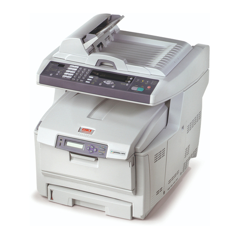
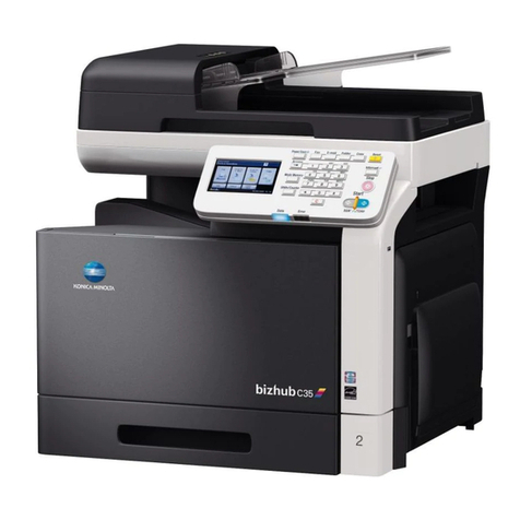
Oki C3200n User manual

Oki Data CONFIDENTIAL
C3200n/C5150n/C5200n
C5400n/C5510MFP
Service Manual
060125A

42615101TH Rev.8 2 /
Oki Data CONFIDENTIAL

42615101TH Rev.8 3 /
Oki Data CONFIDENTIAL
PREFACE
This manual describes the procedures of the maintenance of the C5400/C5200/C5150/C5510/C3200 printers.
The document is produced for maintenance personnel use. For details on the procedures for handling
the C5400/C5200/C5150/C3200n/C5510 of printers, see its user documentation.
Note!
• The descriptions in this manual are subject to change without prior notice.
• In preparing the document, efforts have been made to ensure that the information in it is accurate.
However, errors may be crept into the document. Oki Data assumes no responsibility for any
damage resulting from, or claimed to be the results of, those repairs, adjustments or modifica-
tions to the printers which are made by users using the manual.
• The parts used for the printers are sensitive and, if handled improperly, may be damaged. It is
strongly recommended that the products are maintained by maintenance men registered with
Oki Data.
• Remove static electricity before working.

42615101TH Rev.8 4 /
Oki Data CONFIDENTIAL
CONTENTS
1. SPECIFICATIONS ............................................................................................... 7
1.1 System Configuration ........................................................................................................... 7
1.2 Printer Configuration .......................................................................................................... 10
1.3 Option Configuration .......................................................................................................... 15
1.4 Specifications ..................................................................................................................... 16
1.5 INTERFACE SPECIFICATIONS ........................................................................................ 20
1.5.1 Parallel Interface Specifications (C5400n)...................................... 20
1.5.1.1 Parallel Interface ................................................................................... 20
1.5.1.2 Parallel Interface Connector and Cable ................................................ 20
1.5.1.3 Parallel Interface Level .......................................................................... 20
1.5.1.4 Timing Charts ........................................................................................ 21
1.5.1.5 Parallel I/F Signals ................................................................................ 22
1.5.2 Universal Serial Bus (USB) Interface Specifications(C5400n
C5200n/C5150/C3200n/C5510MFP).......................................... 23
1.5.2.1 USB Interface ........................................................................................ 23
1.5.2.2 USB Interface Connector and Cable ..................................................... 23
1.5.2.3 USB Interface Signals ........................................................................... 23
1.5.3 Network Interface Specifications(C5400/C5200/
C5150/C3200n) .................................................................................................... 24
1.5.3.1 Network Interface .................................................................................. 24
1.5.3.2 Network Interface Connector and Cable ............................................... 24
1.5.3.3 Network Interface Signals ..................................................................... 24
2. OPERATION DESCRIPTION ............................................................................ 25
2.1 Electrophotographic Process Mechanism .......................................................................... 25
2.2 Printing Processes ............................................................................................................. 30
3. PRINTER INSTALLATION ................................................................................. 40
3.1 Precautions and Prohibition .................................................................................................. 40
3.2 Printer Unpacking Procedure ................................................................................................42
3.3 Printer Installation Instructions .............................................................................................. 44
3.4 Packed Units and Attachments ............................................................................................. 45
3.5 Assembly Procedure ............................................................................................................. 46
3.5.1 Printer Main Body .................................................................................................... 46
3.5.2 Power Cable Connection ......................................................................................... 51
3.5.3 Installation of Optional Components ........................................................................ 54
3.5.4 Checking of Optional-Component Recognition ........................................................ 63
3.6 MenuMap Printing ................................................................................................................. 64
3.7 Connection Procedures ........................................................................................................ 67
3.8 Checking of User Paper ........................................................................................................ 69
4. PARTS REPLACEMENT ................................................................................... 70
4.1 Precautions in Replacing Parts .......................................................................................... 70
4.2 Part Replacement Procedures ........................................................................................... 72
4.2.1 Left Side Cover ..................................................................................................... 72
4.2.2 Right Side Cover .................................................................................................. 74
4.2.3 Face-Up Tray........................................................................................................ 76
4.2.4 Rear Cover ........................................................................................................... 77
4.2.5 LED Assy / LED Assy-Springs.............................................................................. 78
4.2.6 Controller PCB...................................................................................................... 79
4.2.7 Print Engine Controller PCB ................................................................................. 83
4.2.8 Top Cover Assy .................................................................................................... 88
4.2.9 Top Cover ............................................................................................................. 90
4.2.10 Controller Panel Assy ........................................................................................... 92
4.2.11 Board-PRP(C5400n//C5200n/C5150n/C3200n)/
Board-PRO(C5510MFP)/ Top Cover Handle ....................................... 93

42615101TH Rev.8 5 /
Oki Data CONFIDENTIAL
4.2.12 Low-Voltage Power Unit / ID-FAN / Low-Voltage Power Unit FAN /
Hopping Motor / Fuser Motor ................................................................................ 94
4.2.13 Board-PRT............................................................................................................ 95
4.2.14 Guide-Eject Assy / Color Registration Assy / Board-PRM.................................... 96
4.2.15 FAN (Fuser) / Belt Motor / High Voltage Power Supply Board / Cover Open Switch 98
4.2.16 MPT-Assy ............................................................................................................. 99
4.2.17 Feeder Unit / Board-RSF / MPT Hopping Roller / Frame Assy Separator /
Cover-Front ......................................................................................................... 100
4.2.18 Main Motors / Solenoid / Paper-End Sensor ...................................................... 101
4.2.19 Feed Roller ......................................................................................................... 103
4.2.20 Shaft Assy-Eject (FU) / Shaft Assy-Eject (FD) / Eject Sensor ............................ 104
4.2.21 Fuser Unit ........................................................................................................... 105
4.2.22 Belt Unit .............................................................................................................. 106
4.3 Parts to lubricate .............................................................................................................. 107
5. MAINTENANCE MENU ................................................................................... 124
5.1 System Maintenance Menu(For Maintenance Staff) ........................................................ 124
5.2 Maintenance Utility ........................................................................................................... 127
5.3 Changing the display language ........................................................................................ 131
5.4 Maintenance Menu Function of the User Menu ............................................................... 132
5.4.1 Maintenance Menu(For End-Users) ................................................................... 132
5.4.2 Self-diagnostic Mode .......................................................................................... 133
5.4.2.1 Operator panel .................................................................................... 133
5.4.2.2 Normal self-diagnostic mode (level 1) ................................................. 137
5.4.2.2.1 Entering self-diagnostic mode (level 1) ............................... 139
5.4.2.2.2 Exiting self-diagnostic mode ............................................... 139
5.4.2.3 Switch scan test .................................................................................. 140
5.4.2.4 Motor and clutch test ........................................................................... 143
5.4.2.5 Test printing ........................................................................................ 145
5.4.2.6 Color registration adjustment test ....................................................... 150
5.4.2.7 Print density adjustment test ............................................................... 150
5.4.2.8 Consumable counter display ............................................................... 151
5.4.2.9 Counter display of numbers of prints and images ............................... 151
5.4.2.10 Switching between Factory and Shipping modes ............................... 152
5.4.2.11 Self-diagnosis function setting ............................................................ 153
5.4.2.12 Waste toner counter display ................................................................ 154
5.4.2.13 LED head serial number display ......................................................... 154
5.4.2.14 Operator panel display ........................................................................ 155
5.4.3 Printing on Controller-Equipped Printer on a Standalone Basis ......................... 160
5.4.4 Switch Press Functions at Printer Power-On ..................................................... 161
5.5 Settings after Parts Replacement .................................................................................... 162
5.5.1 Instructions to exchange the engine control board ............................................. 162
5.5.2 EEPROM Setting after ARC Board/SPY Board/SPA Board Replacement......... 165
5.5.3 Destination Setting [Check Method: Printing demo page (C5400)
Printing Menu Map (C5200, C5150, C3200n, C5510MFP)] ........... 166
5.6 Settings by Hand for Print Density Adjustment ................................................................ 168
6. REGULAR MAINTENANCE ............................................................................ 169
6.1 Parts Replaced Regularly ................................................................................................ 169
6.2 Cleaning ........................................................................................................................... 169
6.3 Cleaning the LED Lens Array .......................................................................................... 169
6.4 Cleaning the Pick-up Roller and the Pad ......................................................................... 171
6.5 Cleaning the Printer Inside ............................................................................................... 172
7. TROUBLESHOOTING PROCEDURES .......................................................... 174
7.1 Precautions before troubleshooting ................................................................................. 174
7.2 Precautions before handling an abnormal image ............................................................ 174

42615101TH Rev.8 6 /
Oki Data CONFIDENTIAL
7.3 Precautions upon handling an abnormal image ............................................................... 174
7.4 Preparing for Troubleshooting ......................................................................................... 174
7.5 Troubleshooting Procedure .............................................................................................. 174
7.5.1 LCD message list ............................................................................................... 175
7.5.2.(1)LCD Display Malfunction ................................................................................. 189
7.5.2.(2)Irregular Operation of the device after turning on the power ........................... 192
7.5.2.(3)Paper Feed Jam(Error 391:1st Tray) ............................................................... 202
7.5.2.(4)Paper Feed Jam (Error 390:Multi-purpose Tray) ............................................. 204

7.5.2.(5)Paper Path Jam(Error 381) ............................................................................. 206
7.5.2.(6)Paper Exit Jam(Error 382) ............................................................................... 211
7.5.2.(7)Duplex Print Jam(Error 370,371,372,373,383)................................................ 214
7.5.2.(8)Paper Size Error (Error 400)............................................................................ 216
7.5.2.(9)ID Unit Up-Down Error(Service Call 140-143) ................................................ 217
7.5.2.(10)Fuser Unit Error(Error 170-177) .................................................................... 218
7.5.2.(11)Motor Fan Error(Error 120,127,051) .............................................................. 219
7.5.2.(12)Print Speed is Slow (Low Performance) ........................................................ 220
7.5.2.(13)Option unit is not recognized ......................................................................... 220
7.5.2.(14)LED head is not recognized(Error 131,132,133,134) .................................... 221
7.5.2.(15)Toner cartridge is not recognized(Error 540,541,542,543) ............................ 222
7.5.2.(16)Fuse Cutout Error (Error 150-155) ................................................................ 226
7.5.2.(17)Dew Condensation Errors (Error 123) ........................................................... 226
7.5.3 Image Problem Troubleshooting ............................................................................ 227
7.5.3.(1)Color is totally pale (Fig.7.2 A ) ....................................................................... 228
7.5.3.(2)Background is dirty (Fig.7.2 B ) ....................................................................... 229
7.5.3.(3)Blank Print (Fig.7.2 C ) .................................................................................... 230
7.5.3.(4)Vertical lines are printed .................................................................................. 231
7.5.3.(5)Cyclic Print Trouble (Refer to Fig.7.2 E ) ......................................................... 232
7.5.3.(6)Color drift is wide. ............................................................................................ 233
7.5.3.(7)Solid Black Print .............................................................................................. 234
7.5.4 Actions Taken after Forced HDD/Flash Initialization .......................................... 235
7.5.5 Network Troubleshooting.................................................................................... 236
7.5.6 Displaying Details of Service Call Error Codes (C5510) ............. 237
7.6 Fuse Checking ................................................................................................................. 238
8. CONNECTION DIAGRAM ............................................................................... 239
8.1 Resistance Checks .......................................................................................................... 239
8.2 PCB Parts Layouts ........................................................................................................... 243

42615101TH Rev.8 7 /
Oki Data CONFIDENTIAL
K LED HEAD
Y LED HEAD
M LED HEAD
C LED HEAD
Environment
Sensor
Operator Panel
Board
Toner Sensor Board
High Voltage Board Low Voltage Board
MCON CPU
Paperfeed
Solenoid
M
KID
Front Sensor Board
Duplex Board 2nd Tray Board
IN1 IN2 WR
M
YID
M
MID
M
CID
M
HOP
1st
P. E
Sensor
Belt Unit
PU-Board
Driver Relay Board
Fuser Inlet
EXIT
Sensor
Density
Sensor
Color
Registration
Board-Right
Color
Registration
Board-Left
M
BELT
M
HEAT
Belt Unit Fuse
Cut-Out
Fuser Fuse Cut-Out/
Up & Low/
Thermistor
Fuse Cut-Out,
Exit,
Motor Control
Color Registration,
Density, Thermistor
Signals
Environment Temperature
Humidity Signals
28MHz
FLASH
8M bit
SRAM
256Kbit
High Voltage Interface,
Fan Control, Cover-Open
Fan, Heater
Control, etc
3.3V, 5V, 24V,
0VL, 0VP
EEPROM
K-ID Y-ID M-ID C-ID Low-Voltage
FAN AC-SW
Fusing
FAN
ID
FAN
Belt
Thermistor
Heater Frame
Thermistor
ID UP/
Down
Cover-
Open
Sensor
K toner
sensor
Y toner
sensor
M toner
sensor
C toner
sensor
Image drum fuse
cut-out
DCON
50MHz
Video
Interface
(data8bit ×4,
fsync ×4,
Isync, wclk)
LVDS
Driver
LAN, USB, Centro I/F HDD
CU Board
CU-FAN
CU Area
DCON I/F, LSYNC Command
Interface
1. SPECIFICATIONS
1.1 System Configuration
C5400
Figure 1-1-1 shows the system configuration of C5400.
Figure 1-1-1

42615101TH Rev.8 8 /
Oki Data CONFIDENTIAL
C5200/C5150/C3200n
Figure 1-1-2 shows the system configuration of C5200/C5150/C3200n.
Figure 1-1-2
K LED HEAD
Y LED HEAD
M LED HEAD
C LED HEAD
ASIC
(ARBOKS)
33MHz
Video
Interface
(data8bit ×4,
fsync ×4,
Isync, wclk)
USB I/F LAN I/F
CU Board
CPU
CU Area
DCON I/F, LSYNC
Environment
Sensor
Operator Panel
Board
Toner Sensor Board
High Voltage Board Low Voltage Board
MCON CPU
Paperfeed
Solenoid
M
KID
Front Sensor Board
Duplex Board 2nd Tray Board
IN1 IN2 WR
M
YID
M
MID
M
CID
M
HOP
1st
P. E
Sensor
Belt Unit
PU-Board
Driver Relay Board
Fuser Inlet
EXIT
Sensor
Density
Sensor
Color
Registration
Board-Right
Color
Registration
Board-Left
M
BELT
M
HEAT
Belt Unit Fuse
Cut-Out
Fuser Fuse Cut-Out/
Up & Low/
Thermistor
Fuse Cut-Out,
Exit,
Motor Control
Color Registration,
Density, Thermistor
Signals
Environment Temperature
Humidity Signals
28MHz
FLASH
8M bit
SRAM
256Kbit
High Voltage Interface,
Fan Control, Cover-Open
Fan, Heater
Control, etc
3.3V, 5V, 24V,
0VL, 0VP
EEPROM
K-ID Y-ID M-ID C-ID Low-Voltage
FAN AC-SW
Fusing
FAN
ID
FAN
Belt
Thermistor
Heater Frame
Thermistor
ID UP/
Down
Cover-
Open
Sensor
K toner
sensor
Y toner
sensor
M toner
sensor
C toner
sensor
Image drum fuse
cut-out
* Except C3200n

42615101TH Rev.8 9 /
Oki Data CONFIDENTIAL
C5510
Figure 1-1-3 shows the system configuration of C5510.
Figure 1-1-3
K LED HEAD
Y LED HEAD
M LED HEAD
C LED HEAD
Environment
Sensor
Operator Panel
Board
Toner Sensor Board
High Voltage Board Low Voltage Board
MCON CPU
Paperfeed
Solenoid
M
KID
Front Sensor Board
IN1 IN2 WR
M
YID
M
MID
M
CID
M
HOP
1st
P. E
Sensor
Belt Unit
PU-Board
Driver Relay Board
Fuser Inlet
EXIT
Sensor
Density
Sensor
Color
Registration
Board
M
BELT
M
HEAT
Belt Unit Fuse
Cut-Out
Fuser Fuse Cut-Out/
Up & Low/
Thermistor
Fuse Cut-Out,
Exit,
Motor Control
Color Registration,
Density, Thermistor
Signals
Heater flame thermistor
Environment Temperature
Humidity Signals
28MHz
FLASH
8M bit
SRAM
256Kbit
High Voltage Interface,
Fan Control, Cover-Open
Fan, Heater
Control, etc
3.3V, 5V, 24V,
0VL, 0VP
EEPROM
K-ID Y-ID M-ID C-ID Low-Voltage
FAN AC-SW
Fusing
FAN
UPDown
sensor
Cover-
Open
SW
K toner
sensor
Y toner
sensor
M toner
sensor
C toner
sensor
Image drum fuse
cut-out
DCON
50/30
MHz
LEISUS Video
Interface
(data8bit ×4,
fsync ×4,
Isync, wclk)
LVDS
Driver
USB I/F
CU Board
CU Area
DCON I/F, LSYNC LEISUS
Command
Interface

42615101TH Rev.8 10 /
Oki Data CONFIDENTIAL
1.2 Printer Configuration
The inside of C5400 printers is composed of the following:
• Electrophotographic Processor
• Paper Paths
• Controller Block (CU and PU)
• Operator Panel
• Power Units (High Voltage Unit and Low Voltage Unit)
Figure 1-2-1 shows the configuration of each printer.
Figure 1-2-1

42615101TH Rev.8 11 /
Oki Data CONFIDENTIAL

42615101TH Rev.8 12 /
Oki Data CONFIDENTIAL
The inside of C5200/C5150/C3200n printers is composed of the following:
• Electrophotographic Processor
• Paper Paths
• Controller Block (CU and PU)
• Operator Panel
• Power Units (High Voltage Unit and Low Voltage Unit)
Figure 1-2-3 shows the configuration of each printer.
Figure 1-2-3

42615101TH Rev.8 13 /
Oki Data CONFIDENTIAL

42615101TH Rev.8 14 /
Oki Data CONFIDENTIAL
The inside of C5510 printers is composed of the following:
• Electrophotographic Processor
• Paper Paths
• Controller Block (CU and PU)
• Operator Panel
• Power Units (High Voltage Unit and Low Voltage Unit)
Figure 1-2-5 shows the configuration of each printer.
Figure 1-2-5

42615101TH Rev.8 15 /
Oki Data CONFIDENTIAL
1.3 Option Configuration
The following options are available for C5400/C5200/C5150/C5510.
(1) 2nd Tray (C5400//C5200/C5150)
(3) Duplex Unit (C5400/C5200/C5150/C3200n)
(4) Expansion Memory (C5400) 64 MB
Recommend to add an optional memory for duplex print, banner print.
(5) Expansion Memory (C5200/C5150/C3200n) 64/256 MB, (C5510)
256MB, Recommend to add an optional memory for duplex print
(C5200/C5150), banner print.
(6) Hard Disk (C5400)
1.4 Specifications

42615101TH Rev.8 16 /
Oki Data CONFIDENTIAL
Category
Physical
Characteristics
(1lbs.=453.6g)
Print Width
Print speed
Print start
Resolution
CPU
RAM
ROM
Power
consumption
Usage
Environment
(Temperature)
Usage
Environment
(Humidity)
Item
Width
Depth
Height
Weight
Print Width
Engine speed
(A4)
First print time
Warm-up time
Quiet mode
LED head
Maximum Input dpi
Output dpi
Modulation
Econo mode
Core
I-Cache, D-Cache
Clock
Bus width
Resident
Option
Program+Font
Power Input
Power save
mode
Idle
Typical operation
Peak
In operating
In non-operating
In storage
(The maximum
is one year)
In transferring
(The maximum
is one month)
In transferring
(The maximum
is one month)
In operating
In non-operating
In storage
In transferring
C3100/C3200 C5150C3200nC5510 C5200 C5400
16.7" (425mm)
22.1" (561mm)
13.6" (345mm)
approx.55lbs (25kg)
A4
90sec
N/A
600dpi
600x1200dpi
N/A
Toner save by reducing lightness
110~127VAC (Range 99~140VAC) / 220~240VAC (Range 198~264VAC)
950W
420W
12PPM (Color)
20PPM (Mono)
6PPM (OHP-Color)
12PPM (OHP-Mono)
9sec(K), 14sec(Color) (A4)
13.6" (345mm)
approx.55lbs (25kg)
14" (355mm)
26.4kg
True 600x1200dpi
True 600x600dpi
True 300x300dpi
PowerPC405PS
16KB,16KB
200MHz
32bit
32 MB
64 / 256 MB DIMM
32 MB (96MB:C520)
64 / 256 MB DIMM
2MB (GDI)
64 MB
64 / 128 / 256 MB DIMM
16MB
(PCL6c)
96MB
256MB
128MB
128/256MB
Less than 20W
120W (Ave.),
850W (Max.)
Less than 25W
130W (Ave.),
850W (Max.)
Less than 16W
110W (Ave.),
850W (Max.)
330W
24MB
(PCL6c + PS3)
True 600x1200dpi
True 600x600dpi
16PPM (Color)
24PPM (Mono) (Default:20PPM)
6PPM (OHP-Color)
12PPM (OHP-Mono)
9sec(K), 13sec(Color) (A4)
10°C~32°C, 17°C~27°C(Temperature of full color print quality assurance)
0°C~43°C, Power OFF
-10°C~43°C, There are drums and toners
-29°C~50°C, There are drums but no toners
-29°C~50°C, There are drums and toners
20%~80%, 50%~70%(Humidity of full color print quality assurance)
Max wet bulb temperature 25°C
10%~90%, Max wet bulb temperature 26.8°C, Power OFF
10%~90%, Max wet bulb temperature 35°C
10%~90%, Max wet bulb temperature 40°C
PowerPC750CX
32KB, 32KB (256KB inside L2)
400MHz
64bit

42615101TH Rev.8 17 /
Oki Data CONFIDENTIAL
1.5
KP (K)
1.5KP (C)
N/A1.5
KP (K)
1.5KP (C)
N/A
Item
Printer life
Printer duty
(M=L/12, A=L/12/5)
MTBF (2.3% duty)
MPBF
MTTR
Toner life
(5%
duty
)
ODA
ODA
Image drum life
Transfer belt life
Fuser life
Operating
Standby
Power save mode
Input (1st bin)
Input (2nd bin)
Input
(Manual/Auto)
Output
Duplex
Legal/Universal
or A4/Universal
cassette
Auto front feeder
or manual feeder
Duplex
1st bin
2nd bin
Manual or Auto
Duplex
Standard :
3KP (K),3KP (C)
High Capa :
5KP (K), 5KP (C)
N/A
Standard :
1.5KP (K),
1.5KP (C)
Standard
:
1.5KP (K),
1.5KP (C)
High Capa
:
3KP (K),
3KP (C)
N/A
Standard :
3KP (K),
3KP (C)
High Cap :
5KP (K),
5KP (C)
C5200
Standard :
3KP (K), 3KP (C)
High Cap :
5KP (K), 5KP (C)
C5400
Standard : 3KP (K), 3KP (C)
High Cap : 5KP (K), 5KP (C)
C540
Standard : 5KP (K), 5KP (C)
C3100/C5510
Standard : 3KP (K), 3KP (C)
C3200
Standard :
1.5KP (K), 1.5KP (C)
High Capa : 3KP (K), 3KP (C)
C5400
Standard : 3KP (K), 3KP (C)
High Capa : 5KP (K), 5KP (C)
C540
Standard : 5KP (K), 5KP (C)
Standard :
3KP (K), 3KP (C)
High Cap :
5KP (K), 5KP (C)
Category
Life
Acoustic noise
Paper handling
Paper size
Minimum
paper
size
1st cassette : Legal13/13.5/14,Letter,Exective,A4,A5,B5,A6
2nd cassette : Legal13/13.5/14,Letter,Exective,A4,A5,B5
(Multi Purpose Tray)
Legal13,Legal13.5,Legal14,Letter,Exective,A4,A5,B5,A6,C5,DL,Com-9, Com-
10,Monarch,CustomSize,Banner upto 1200mm
(If the length exceeds 356, the width has to be within 210~215.9)
4.1"x5.8"(105x148mm:A6)
4.1"x5.8" (105x148mm:A6)
5.8"x8.3" (148x210mm:A5)
Legal13/13.5/14,Letter,Exective,A4,B5,A5
Custom Size (within size and weight limits)
N/A
N/A
5.8"x8.3" (148x210mm:A5)N/A
420KP, 5 years
Max. 50,000 pages/month
Average 4,000 pages/month
N/A
40,000 pages
20 minutes
ODA/OEL/AOS/ODC
Starter toner (accessory)
Standard/High Capacity
15,000 pages (3P/J)
7,500 pages (1P/J)
22,000 pages (continuous)
Auto Drum Counter reset
50,000 pages (A4 size, 3P/J) Counter Auto Reset
45,000 pages (A4 size) Counter Auto Reset
Multi purpose tray standard.
50 OHPs or 100 sheets (80gsm) or 10 env.
250 sheets (80gsm), face down / 100 Sheets (80gsm) Face Up Tray
37dB (ISO 7779 Front)
Background Level
Legal/Univ cass 300 sheets (80gsm)
Legal/Univ cass (opt) 530 sheets (80gsm)
Option
52dBA (ISO 7779 Front)
(without option unit)
No option supported
54dBA (ISO 7779 Front)
(without option unit)
No option supported
C5510 5150C3200 C5200 C5400
1.5KP (K)
1.5KP (C)
1.5KP (K)
1.5KP (C)
750
P (K)
750P (C)
C5510
1.5KP (K), 1.5KP (C)
C3200
750P (K), 750P (K)
C5510
3KP (K), 3KP (C)
C5510
1.5KP (K), 1.5KP (C)
C5400
1.5KP (K), 1.5KP (C)
C5200
1.5KP (K)
1.5KP (C)

42615101TH Rev.8 18 /
Oki Data CONFIDENTIAL
N/A
4 (Greenx1,
Dark Amberx3)
2
16ch, 2line ( Roman/Kana ) No Paper size indicator
2
(Greenx1, Dark Amberx1)
6
Category
Paper weight
Operator panel
Status switch,
Sensor
Communication
interface
Emulation
Font
Item
1st bin
2nd/3rd bin
Manual or Auto
Duplex
LCD
LED (Color)
Switch
Paper end
Paper low
Toner low
Cover open
Fuser temperature
Paper size
Stacker full
Standard
(On board)
Options
(Removable)
I/O switch
Standard
Options
(Removable)
Emulation switch
Bitmap
Typeface
Scalable 1
Typeface
Scalable 2
Typeface
Scalable 3
Typeface
Rasterizer
Barcode
OCR
Japanese
PCL Fonts
Japanese
PS Fonts
N/A
20~53lb. (75~203gsm) OHP Available
Over sea : 20~28lb. (75~105gsm)
17~47lb. (64~176gsm)
17~32lb. (64~120gsm)
Available
N/A
Available (Y,M,C,K)
Available
Available
N/A
N/A
Auto
USB (2.0)
Ethernet
N/A
USB (2.0)
Ethernet
IEEE-1284
Parallel
N/A
USB (2.0)
IEEE-1284
Parallel
PS & NIC
upgradable
DIMM (Option)
USB (2.0)
IEEE-1284
Parallel
PCL (PCL5c, HP-GL) /
PCL XL2.1
SIDM
(IBM-PPR, EPSON-FX)
PostScript3 (Clone)
N/A
Auto
USB (2.0)
N/A
C5510 C5150C3200n C5200 C5400
Agfa
1(line printer)
Agfa MicroType
86
N/A
Agfa MicroType
136
Agfa UFST 4.0
(PCL)
USPS
OCR-A,B
PCL
(PCL5c,
HP-GL) /
PCL XL2.1
SIDM
(IBM-PPR,
EPSON-
FX)
PS option
(DIMM option
available)
N/A
GDI
Hiper-C
N/A
N/A
N/A
N/A
N/A
N/A
N/A
N/A
N/A
N/A
N/A
N/A
N/A
N/A
N/A

42615101TH Rev.8 19 /
Oki Data CONFIDENTIAL
Category
Slot or Socket
(Flash SIMM)
Option
(Removable)
Shipping
Configuration
Product name
Other
Item
Slot
Socket
Resident Flash
Mem
RAM set
Interface
Tray mechanism
Cassette
Duplex
Other
ODA
OEL
INTER
OEM
ODA
OEL
AOS
USB-IF Logo
Windows Logo
Operation in
UPS
YES
YES
An operation in UPS(the uninterruptible power source) is not assured.
Do not use UPS.
-
C5510
C5510
C5200n/ne
C5200n
C5200n
C5400n
C5400n
C5400n
C5150n/C3200n
C3200n
C3200n
C5400
-
-
64, 256 MB
N/A
No 2nd tray
available
N/A
Not available
2nd tray mecha
Legal/Univ (530)
Available
N/A
64, 128, 256 MB
N/A
GDI model
GDI model
GDI model
2.5" IDE HDD User installable
N/AEthernet
(soft NIC)
upgradable with
DIMM exchage
and take off
connector cover
PCL+PS model
PCL+PS model
PCL+PS model
PCL model
-
-
N/A
No slot/socket for Flash
512KB
Flash ROM
2MB Flash ROM 4MB Flash ROM
C5510 C5150C3200n C5200 C5400
Note!
There is no compatibility among C5200/C5150/C3200 expansion memory and
C5400 expansion memory.

42615101TH Rev.8 20 /
Oki Data CONFIDENTIAL
Item Description
Mode Compatibility mode, Nibble mode, ECP mode
Data bit length 8 bits: Compatibility mode, 4bits: Nibble mode,9 bits: ECP mode
118
1936
1.5 INTERFACE SPECIFICATIONS
1.5.1 Parallel Interface Specifications (C5400)
1.5.1.1 Parallel Interface
1.5.1.2 Parallel Interface Connector and Cable
1) Connector
Printer side: 36-pin receptacle
Type 57LE-40360-12 (D56) (made by Daiichi Denshi) or equivalent
Cable side: 36-pin plug
Type 57FE-30360-20N (D8) (made by Daiichi Denshi) or equivalent
Connector Pin Arrangement Viewed from Cable Side
2) Cable
Cable length: 1.8 m max.
(A shielded cable composed of twisted pair wires is recommended for noise prevention.)
1.5.1.3 Parallel Interface Level
LOW: 0 V to +0.8 V
HIGH: +2.4 V to 5.0 V
Other manuals for C3200n
21
This manual suits for next models
13
Table of contents
Other Oki All In One Printer manuals