2. Allgemeine Sicherheitsmassnahmen in bezug auf die Wartung
- Während der Wartung das Gerät ausschalten und das Netzkabel herausziehen (ausser Wartung,
die bei einem eingeschalteten Gerät, durchgeführt werden muss).
- Das Netzkabel herausziehen und den Bereich um die Steckerpole und die Steckdose die
Umgebung in der Nähe von den Steckerzacken und der Steckdose wenigstens einmal im Jahr
reinigen. Wenn Staub sich in dieser Gegend ansammelt, kann dies ein Feuer verursachen.
- Wenn die Teile auseinandergenommen werden, wenn nicht anders in diesem Handbuch usw
erklärt, ist das Zusammenbauen in umgekehrter Reihenfolge durchzuführen. Aufpassen, dass
kleine Teile wie Schrauben, Dichtungsringe, Bolzen, E-Ringe, Stern-Dichtungsringe,
Kabelbäume nicht an den verkehrten Stellen eingebaut werden.
- Grundsätzlich darf das Gerät mit enfernten oder auseinandergenommenen Teilen nicht in
Betrieb genommen werden.
- Das PC-Board muss in einer Anti-elektrostatischen Hülle gelagert werden. Nur Mit einer
Manschette bei Betätigung eines Armbandes anfassen, sonst könnte es sein, dass die
integrierten Schaltkreise durch statische Elektrizität beschädigt werden.
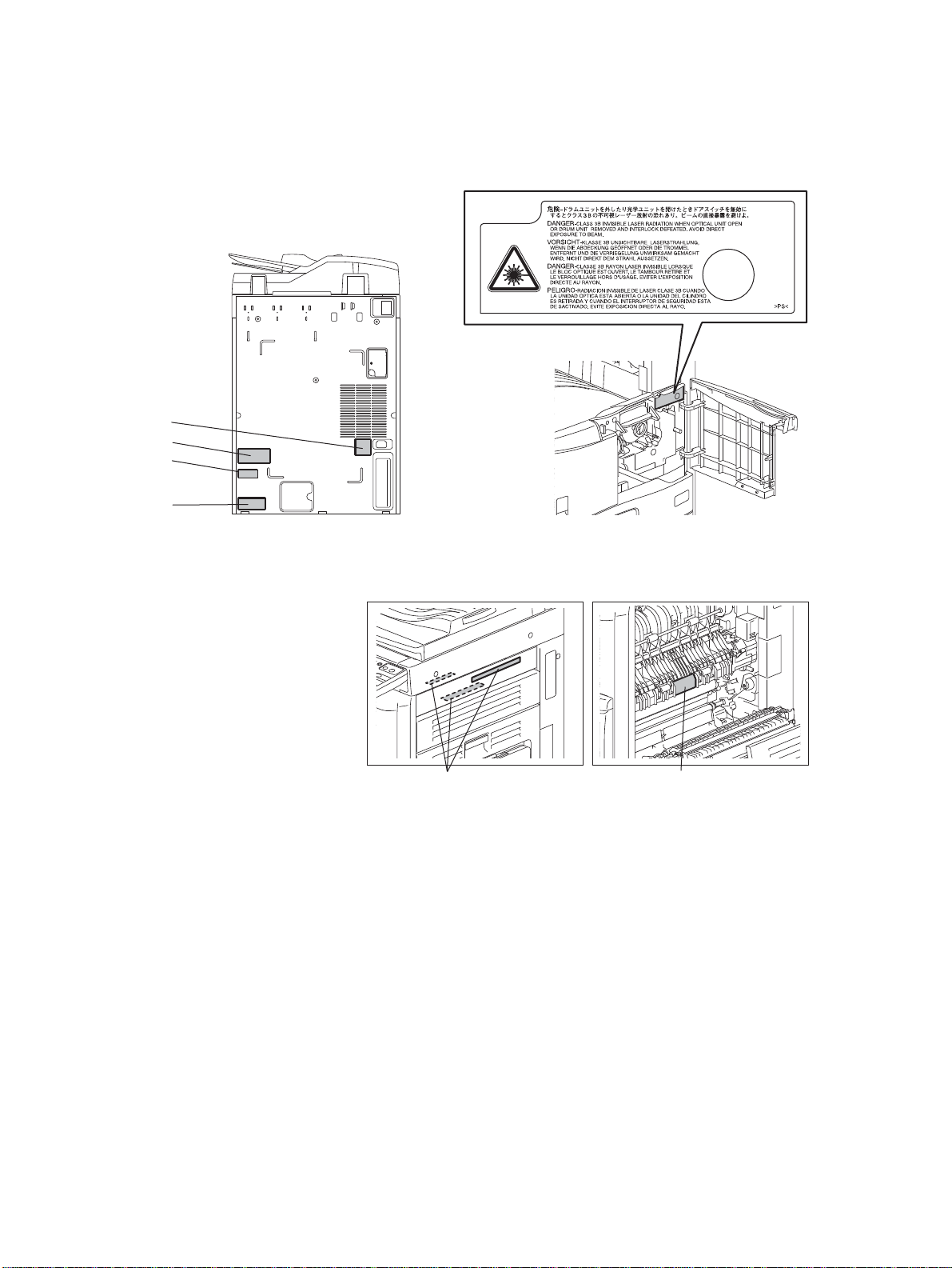
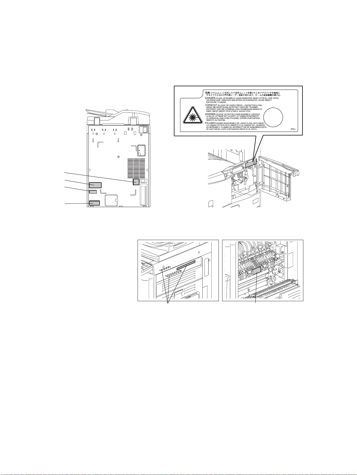
- Setzen Sie sich während der Wartungsarbeiten nicht dem Laserstrahl aus. Dieses Gerät ist mit
einer Laserdiode ausgestattet. Es ist unbedingt zu vermeiden, direkt in den Laserstrahl zu
blicken. Keine reflektierenden Teile oder Werkzeuge, wie z. B. Schraubendreher, in den Pfad des
Laserstrahls halten. Vor den Wartungsarbeiten sämtliche reflektierenden Metallgegenstände, wie
Uhren, Ringe usw., entfernen.
- Auf keinen Fall Hochtemperaturbereiche, wie die Belichtungslampe, die Fixiereinheit, die
Heizquelle und die umliegenden Bereiche, berühren.
- Auf keinen Fall Hochspannungsbereiche, wie die Ladeeinheiten, die Transferwalze, die
Entwicklereinheit, den Hochspannungstransformator, den Steuerumrichter für die
Belichtungslampe, den Umrichter für die LCD-Hintergrundbeleuchtung und das Netzgerät,
berühren. Insbesondere sollten die Platinen dieser Komponenten nicht berührt werden, da die
Kondensatoren usw. auch nach dem Ausschalten des Geräts noch elektrisch geladen sein
können.
- Vor dem Berühren potenziell gefährlicher Bereiche (z. B. drehbare oder betriebsrelevante
Bereiche, wie Zahnräder, Riemen, Riemenscheiben, Lüfter und die Laseraustrittsöffnung der
optischen Lasereinheit) sicherstellen, dass das Gerät sich nicht bedienen lässt.
- Beim Entfernen von Abdeckungen vorsichtig vorgehen, da sich darunter scharfkantige
Komponenten befinden können.
- Bei Wartungsarbeiten am eingeschalteten Gerät dürfen keine unter Strom stehenden, drehbaren
oder betriebsrelevanten Bereiche berührt werden. Nicht direkt in den Laserstrahl blicken.
- Ausschließlich vorgesehene Werkzeuge und Hilfsmittel verwenden.
- Empfohlene oder gleichwertige Messgeräte verwenden.
- Nach Abschluss der Wartungsarbeiten das Gerät in den ursprünglichen Zustand zurück
versetzen und den einwandfreien Betrieb überprüfen.
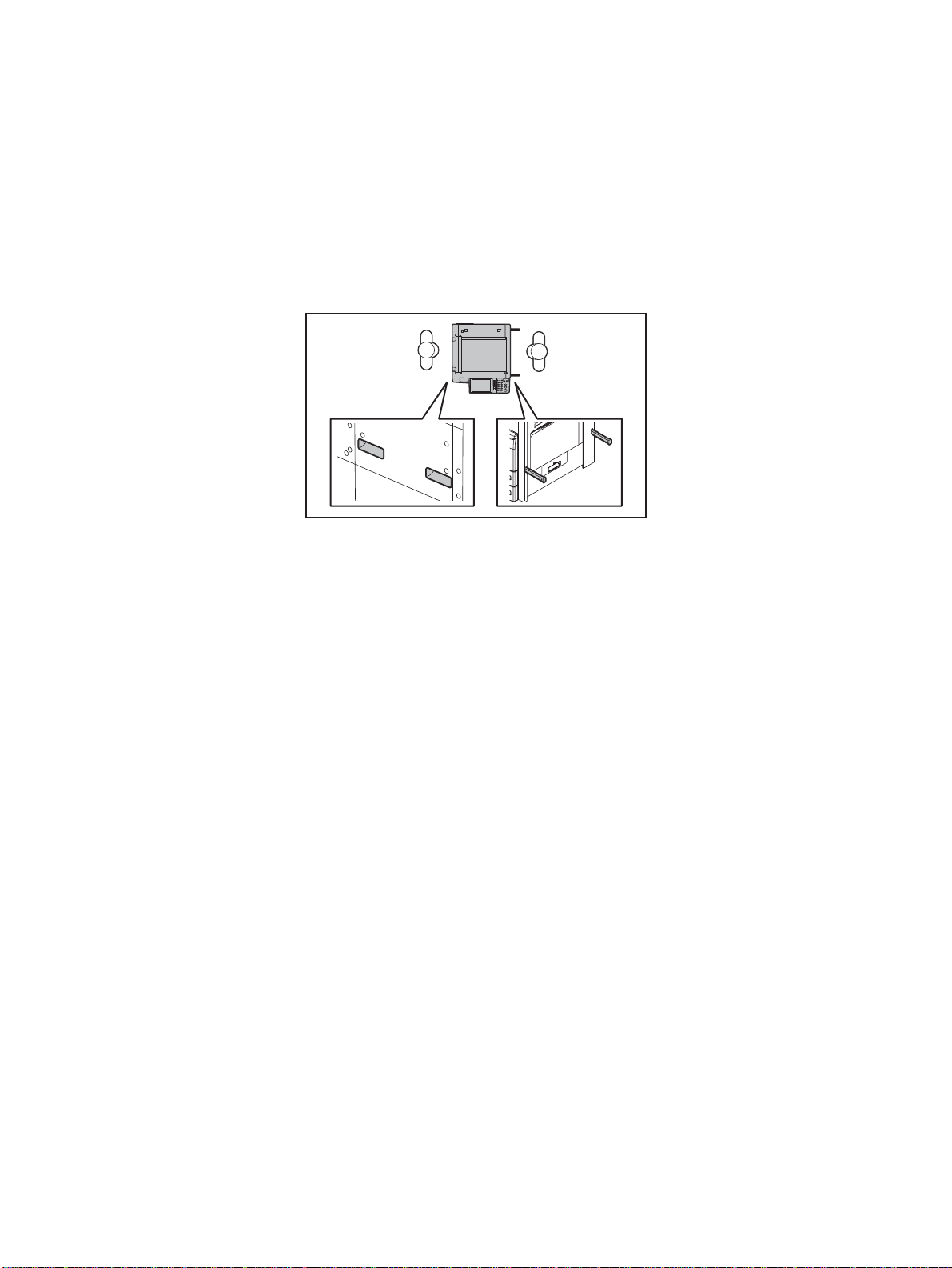
- Das berührungsempfindliche Bedienungsfeld stets vorsichtig handhaben und keinen Stößen
aussetzen. Wenn die Oberfläche beschädigt wird, kann dies zu Funktionsstörungen führen.
3. Sicherheitsrelevante Wartungsteile
- Der Leistungsschutzschalter, der Türschalter, die Sicherung, der Thermostat, die
Thermosicherung, der Thermistor, die IC-RAMs einschließlich der Lithiumakkus usw. sind
besonders sicherheitsrelevant. Sie müssen unbedingt korrekt gehandhabt und installiert werden.
Wenn diese Teile kurzgeschlossen und funktionsunfähig werden, kann dies zu
schwerwiegenden Schäden, wie einem Abbrand, führen. Kurzschlüsse sind zu vermeiden, und
es sind ausschließlich Teile zu verwenden, die von der OKI DATA CORPORATION. empfohlen
sind.
Vorsicht: Vor Benutzung der Manschette der Betätigung des Armbandes, das Netzkabel
des Gerätes herausziehen und prüfen, dass es in der Nähe keine geladenen
Gegenstände, die nicht isoliert sind, gibt.