Oki B4350 Series User manual

Oki Data CONFIDENTIAL
B4350/B4350n
Service Manual
060125A

42641101TH Rev.1 2 /
Oki Data CONFIDENTIAL
1 2004-04-01 ISSUE ME5 Ono
Rev.No. Date
No.
Corrected items
Page Description of change
Person in
charge
Document Revision History

42641101TH Rev.1 3 /
Oki Data CONFIDENTIAL
PREFACE
This Maintenance Manual describes the field maintenance methods for B4350 Monochrome LED Page
Printers.
This manual is written for use by service persons. Please note that you should refer to the Printer Handbook
for the handling and operating methods of the equipment.

42641101TH Rev.1 4 /
Oki Data CONFIDENTIAL
CONTENTS
1. CONFIGURATION.................................................................................................... 7
1.1 System Configuration ....................................................................................... 7
1.2 Printer Configuration ......................................................................................... 8
1.3 Optional Configuration ...................................................................................... 9
1.4 Specification ................................................................................................... 11
1.5 Safety Standards ............................................................................................ 13
1.5.1 Certification Label ...................................................................................................... 13
1.5.2 Warning Label ........................................................................................................... 13
1.5.3 Warning/Caution Marking .......................................................................................... 14
2. PARTS REPLACEMENT........................................................................................ 15
2.1 Precautions for Parts Replacement ................................................................ 15
2.2 Parts Layout.................................................................................................... 17
2.3 How to Change Parts...................................................................................... 20
2.3.1 Upper Cover Assy ..................................................................................................... 21
2.3.2 LED Head .................................................................................................................. 22
2.3.3 Operator Panel Assy ................................................................................................. 23
2.3.4 Lower Base Unit ........................................................................................................ 24
2.3.5 Pulse Motor (Main/Drum) .......................................................................................... 25
2.3.6 Pulse Motor (Registration) ......................................................................................... 26
2.3.7 Pulse Motor (Hopping)............................................................................................... 27
2.3.8 Face Up Stacker Assy ............................................................................................... 28
2.3.9 Eject Roller Assy ....................................................................................................... 29
2.3.10 Motor Assy ................................................................................................................. 30
2.3.11 Hopping Roller Shaft Assy ......................................................................................... 31
2.3.12 Stacker Cover Assy ................................................................................................... 32
2.3.13 Registration Roller ..................................................................................................... 33
2.3.14 Roller Transfer Assy .................................................................................................. 34
2.3.15 Fusing Unit ................................................................................................................ 35
2.3.16 Back-up Roller ........................................................................................................... 36
2.3.17 Sensor Plate (Inlet) .................................................................................................... 37
2.3.18 Sensor Plate (Outlet), Sensor Wire Assy .................................................................. 38
2.3.19 Manual Feed Guide Assy .......................................................................................... 39
2.3.20 Sensor Plate (Paper Supply) ..................................................................................... 40
2.3.21 GRV-2 PCB ............................................................................................................... 41
2.3.22 Power Supply Board and High Voltage/Sensor Board .............................................. 42
2.3.23 Cassette Guide L Assy .............................................................................................. 43
2.3.24 Cassette Guide R Assy ............................................................................................. 44
3. ADJUSTMENT........................................................................................................ 45
3.1 Maintenance Modes and Functions ................................................................ 45
3.1.1 User Maintenance Mode (Administrator Menu) ......................................................... 45
3.1.2 System Maintenance Mode (System Maintenance Menu) ........................................ 46
3.1.3 EEPROM Initial Setting Range for Events................................................................. 48
3.2 Adjustment When Replacing a Part ................................................................ 49
3.2.1 Uploading/Downloading EEPROM data .................................................................... 49
4. PERIODICAL MAINTENANCE .............................................................................. 50
4.1 Periodical Replacement Parts ........................................................................ 50

42641101TH Rev.1 5 /
Oki Data CONFIDENTIAL
4.2 Cleaning.......................................................................................................... 50
4.2.1 Cleaning of LED Lens Array ...................................................................................... 50
4.2.2 Cleaning Page Function ............................................................................................ 51
5. TROUBLESHOOTING PROCEDURES ................................................................. 52
5.1 Troubleshooting Tips ...................................................................................... 52
5.2 Points to Check before Correcting Image Problems....................................... 52
5.3 Tips for Correcting Image Problems ............................................................... 52
5.4 Preparation for Troubleshooting ..................................................................... 53
5.5 Troubleshooting Flow ..................................................................................... 53
5.5.1 LCD Status Message/Problem List............................................................................ 53
5.5.2 LCD Message Troubleshooting ................................................................................. 59
5.5.3 Image Troubleshooting .............................................................................................. 67
6. WIRING DIAGRAM................................................................................................ 76
6.1 Interconnect Signal Diagram .......................................................................... 76
6.2 PCB Layout and Connector Signal List .......................................................... 77
6.3 Resistance Check ........................................................................................... 89
APPENDIX A RS-232C SERIAL INTERFACE (OPTION) ......................................... 91
APPENDIX B CENTRONICS PARALLEL INTERFACE............................................ 96
APPENDIX C UNIVERSAL SERIAL BUS (USB)..................................................... 105
APPENDIX D LOOP TEST (RS-232C INTERFACE) ............................................... 111
APPENDIX E DIAGNOSTICS TEST ........................................................................ 112

42641101TH Rev.1 6 /
Oki Data CONFIDENTIAL
APPENDIX G HIGH CAPACITY SECOND PAPER FEEDER ................................. 138
1. OUTLINE ...................................................................................................... 138
1.1 Functions ................................................................................................................. 138
1.2 External View and Component Names ................................................................... 138
2. MECHANISM DESCRIPTION ...................................................................... 139
2.1 General Mechanism ................................................................................................ 139
2.2 Hopper Mechanism ................................................................................................. 139
3. PARTS REPLACEMENT .............................................................................. 140
3.1 Precautions Concerning Parts Replacement .......................................................... 140
3.2 Parts Layout ............................................................................................................ 141
3.3 Parts Replacement Methods ................................................................................... 142
3.3.1 Stepping Motor (Hopping) ......................................................................... 143
3.3.2 TQSB-2 PCB ............................................................................................. 145
3.3.3 Hopping Roller Shaft Assy and One-way Clutch Gear .............................. 145
4. TROUBLESHOOTING.................................................................................. 146
4.1 Precautions Prior to the Troubleshooting ................................................................ 146
4.2 Preparations for the Troubleshooting ...................................................................... 146
4.3 Troubleshooting Method .......................................................................................... 147
4.3.1 LCD Status Message List .......................................................................... 147
5. CONNECTION DIAGRAM ............................................................................ 149
5.1 Interconnection Diagram ......................................................................................... 149
5.2 PCB Layout ............................................................................................................. 149
6. PARTS LIST ................................................................................................. 150
APPENDIX H NETWORK INTERFACE (OPTION).................................................. 156
42641101TH Rev.1 7 /
Oki Data CONFIDENTIAL
1. CONFIGURATION
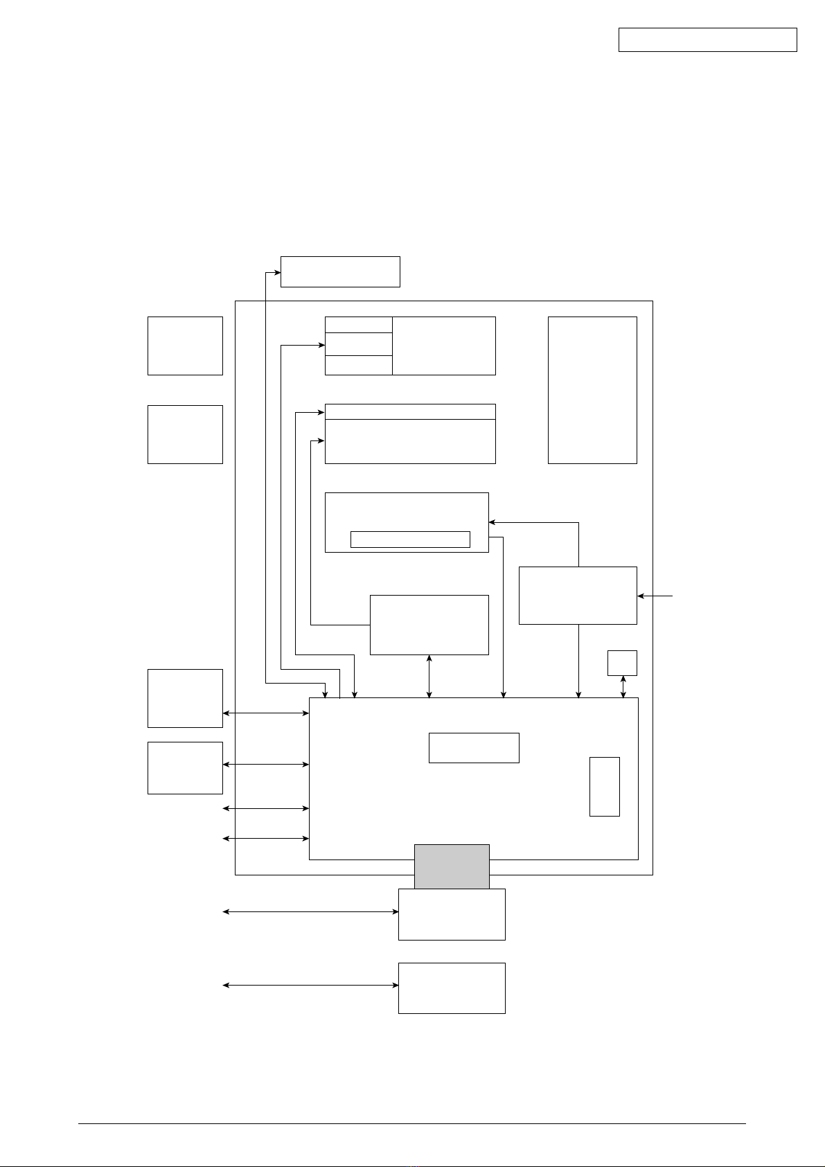
1.1 System Configuration
B4350 consists of control and engine blocks in the standard configuration, as shown in Figure 1-1.
In addition, the options marked with asterisk(*) are available.
Figure 1-1
Operator Panel
LCD : 1
LED : 1
SW : 8
Drum Motor
Paper
Cassette
ID
Unit
Paper Feeding
Mechanism
(First Tray Unit)
Registration
Motor
Hopping Motor
LED Head
Electrophotogarphic
Processing Unit
Fuser Unit
Halogen-Lamp
High Voltage /
Sensor Board
ROM DIMM
*
High Capacity
Second Paper
Feeder
*
Multi Purpose
Feeder
IEEE1284
USB
Network
RS232C
*
Network
Board
OR
*
RS232C
Board
** : Optional
AC
INPUT
Power Supply
Board
Face Down
Stacker
FAN
RAM
DIMM
*
Main Control Board
42641101TH Rev.1 8 /
Oki Data CONFIDENTIAL
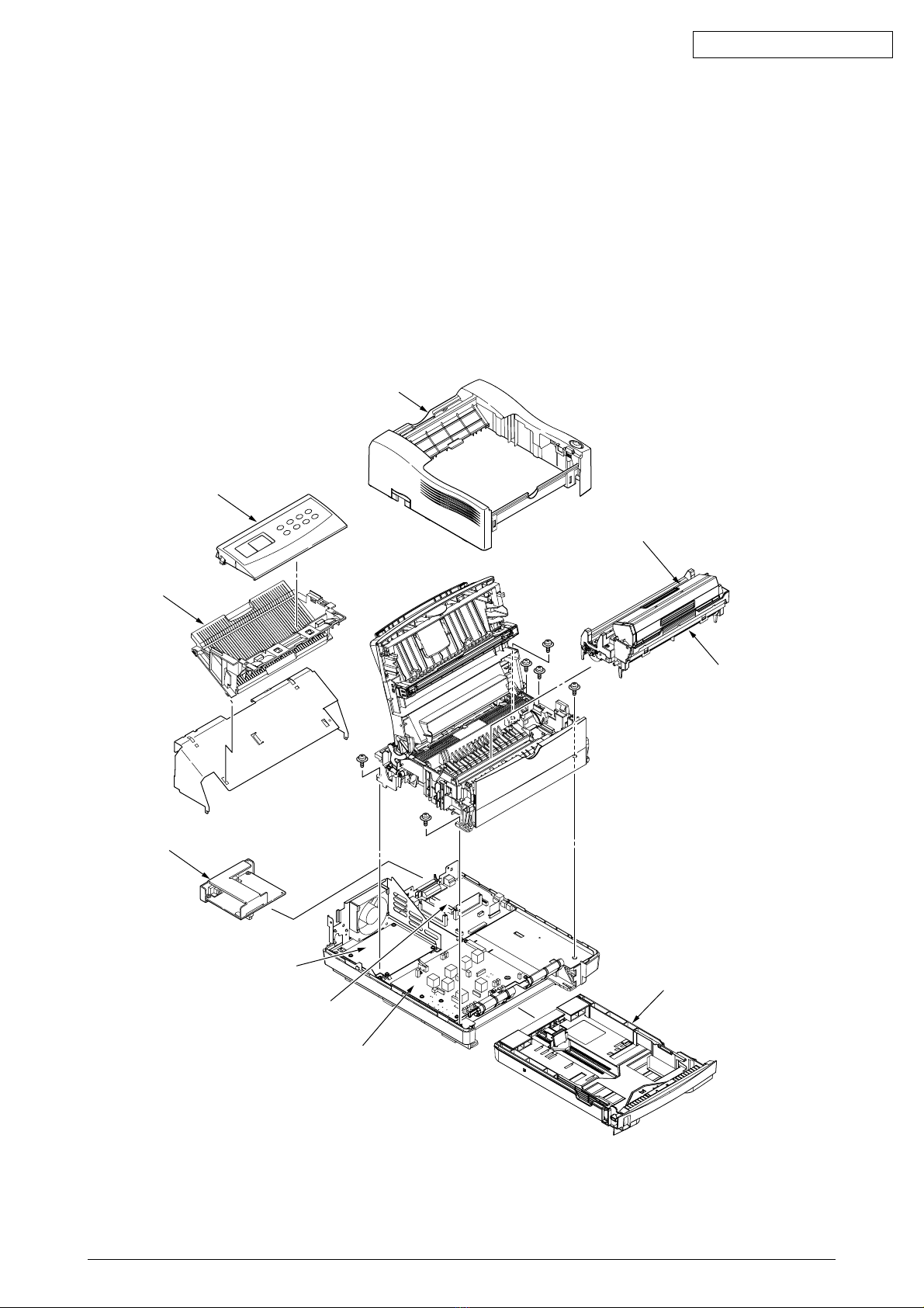
1.2 Printer Configuration
The printer unit consists of the following hardware components:
• Electrophotographic Processor
• Paper Feeder
• Controller
• Operator Panel
• Power Supply Unit
The printer unit configuration is shown in Figure 1-2.
Figure 1-2
Upper cover
Operator panel assy
Stacker assy
Optional board
Legal/universal paper cassette
Image drum unit(Type 9)
(consumable)
Toner-cartridge(Type 9)
(consumable)
Power supply
High Voltage / Sensor board
Main control board

42641101TH Rev.1 9 /
Oki Data CONFIDENTIAL
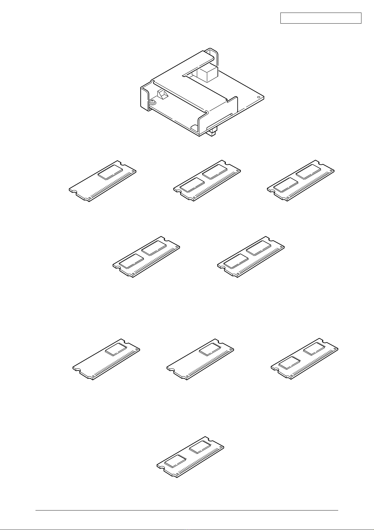
1.3 Optional Configuration
The options shown below are available for use with B4350. These are available separately from the
printer unit.
(1) High Capacity Second Paper Feeder
(3) RS-232C Serial Interface Board
42641101TH Rev.1 10 /
Oki Data CONFIDENTIAL
(5) SDRAM DIMM
(6) Flash DIMM
(4) Network Interface Board(Soft NIC CARD)
(7) Postscript 3 Emulation DIMM
(i) 16MB (ii) 32MB (iii) 64MB
(iv) 128MB (v) 256MB
(i) 1MB (ii) 8MB (iii) 16MB
Other manuals for B4350 Series
2
This manual suits for next models
1
Table of contents
Other Oki Printer manuals


Oki
Oki C7000 User manual

Oki
Oki C831 User manual

Oki
Oki B4600 Series User manual

Oki
Oki C810n Installation instructions

Oki
Oki C8800dn Owner's manual

Oki
Oki C712 User guide

Oki
Oki C7500 V2 Installation and maintenance instructions

Oki
Oki ML6300FB User manual

Oki
Oki OKIPAGE14e Training manual

Oki
Oki MPS6150c Service manual


