MiTAC TYAN S5539 User manual

http://www.tyan.com
1
S5539
Version 1.0
Copyright
Copyright © 2016 MiTAC International Corporation. All rights reserved. No part of
this manual may be reproduced or translated without prior written consent from
MiTAC International Corporation.
Trademark
All registered and unregistered trademarks and company names contained in this
manual are property of their respective owners including, but not limited to the
following.
TYAN®is a trademark of MiTAC International Corporation.
Intel®is a trademark of Intel®Corporation.
AMI, AMI BIOS are trademarks of AMI Technologies.
Microsoft®, Windows®are trademarks of Microsoft Corporation.
Winbond®is a trademark of Winbond Electronics Corporation.
Notice
Information contained in this document is furnished by MiTAC International
Corporation and has been reviewed for accuracy and reliability prior to printing.
MiTAC assumes no liability whatsoever, and disclaims any express or implied
warranty, relating to sale and/or use of TYAN®products including liability or
warranties relating to fitness for a particular purpose or merchantability. MiTAC
retains the right to make changes to product descriptions and/or specifications at
any time, without notice. In no event will MiTAC be held liable for any direct or
indirect, incidental or consequential damage, loss of use, loss of data or other
malady resulting from errors or inaccuracies of information contained in this
document.
All manuals and user guides at all-guides.com
all-guides.com

http://www.tyan.com
2
Contents
S5539............................................................................................................ 1
Before you begin….................................................................................... 3
Chapter 1: Instruction ................................................................................ 4
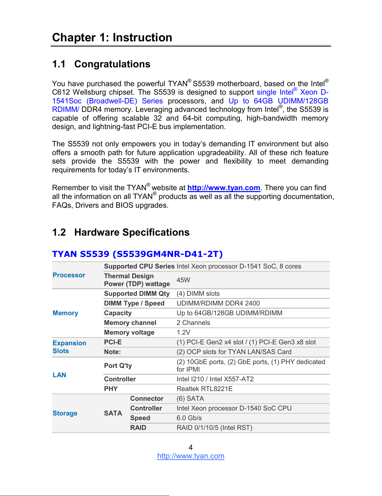
1.1 Congratulations ................................................................................. 4
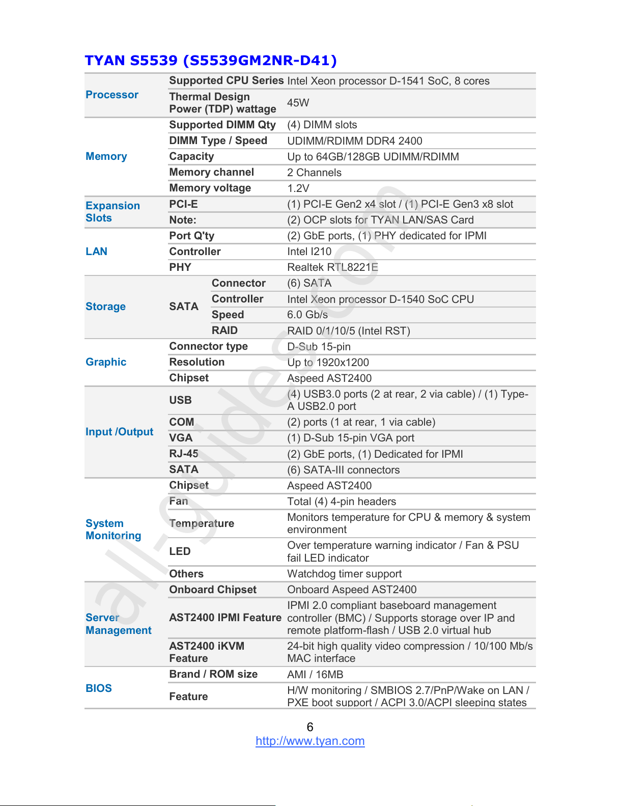
1.2 Hardware Specifications.................................................................... 4
1.3 Software Specifications ..................................................................... 7
Chapter 2: Board Installation..................................................................... 8
2.1 Board Image ...................................................................................... 9
2.2 Block Diagram ................................................................................. 10
2.3 Motherboard Mechanical Drawing................................................... 11
2.4Board Parts, Jumpers and Connectors ........................................... 12
2.5Installing the Processor and Heatsink ............................................. 18
2.6Tips on Installing Motherboard in Chassis ...................................... 19
2.7Installing the Memory ...................................................................... 21
2.8Attaching Drive Cables .................................................................... 25
2.9Installing Add-In Cards .................................................................... 26
2.10 Connecting External Devices ........................................................ 27
2.11 Installing the Power Supply ........................................................... 28
2.12 Finishing Up................................................................................... 28
Chapter 3: BIOS Setup ............................................................................. 29
3.1 About the BIOS................................................................................ 29
3.2 Main Menu....................................................................................... 31
3.3 Advanced Menu............................................................................... 32
3.4 Intel RCSetup Menu ........................................................................ 59
3.5Server Management ........................................................................ 82
3.6 Security............................................................................................ 85
3.7Boot ................................................................................................. 86
3.8Save & Exit ...................................................................................... 88
Chapter 4: Diagnostics............................................................................. 90
4.1 Flash Utility ...................................................................................... 90
4.2 AMIBIOS Post Code (Aptio) ............................................................ 91
Appendix I: Fan and Temp Sensors ....................................................... 98
Glossary................................................................................................... 101
Technical Support .................................................................................. 107
All manuals and user guides at all-guides.com

http://www.tyan.com
3
Before you begin…
Check the box contents!
The retail motherboard package should contain the following:
1 x S5539 Motherboard
1 x Rear IO shielding
1 x S5539 Quick Installation Guide
1 x TYAN®Driver CD
2 x SATA Single Cable
1 x external USB 3.0 Cable(optional)
IMPORTANT NOTE:
Sales samples may not come with any of the accessories listed above.
We also provide USB 3.0 cable in our optional kit. If you need an external
USB 3.0 cable, please contact your sales representative to help order
accessories.
All manuals and user guides at all-guides.com

http://www.tyan.com
4
Chapter 1: Instruction
1.1 Congratulations
You have purchased the powerful TYAN® S5539 motherboard, based on the Intel®
C612 Wellsburg chipset. The S5539 is designed to support single Intel®Xeon D-
1541Soc (Broadwell-DE) Series processors, and Up to 64GB UDIMM/128GB
RDIMM/ DDR4 memory. Leveraging advanced technology from Intel®, the S5539 is
capable of offering scalable 32 and 64-bit computing, high-bandwidth memory
design, and lightning-fast PCI-E bus implementation.
The S5539 not only empowers you in today‟s demanding IT environment but also
offers a smooth path for future application upgradeability. All of these rich feature
sets provide the S5539 with the power and flexibility to meet demanding
requirements for today‟s IT environments.
Remember to visit the TYAN® website at http://www.tyan.com. There you can find
all the information on all TYAN®products as well as all the supporting documentation,
FAQs, Drivers and BIOS upgrades.
1.2 Hardware Specifications
TYAN S5539 (S5539GM4NR-D41-2T)
Processor
Supported CPU Series
Intel Xeon processor D-1541 SoC, 8 cores
Thermal Design
Power (TDP) wattage
45W
Memory
Supported DIMM Qty
(4) DIMM slots
DIMM Type / Speed
UDIMM/RDIMM DDR4 2400
Capacity
Up to 64GB/128GB UDIMM/RDIMM
Memory channel
2 Channels
Memory voltage
1.2V
Expansion
Slots
PCI-E
(1) PCI-E Gen2 x4 slot / (1) PCI-E Gen3 x8 slot
Note:
(2) OCP slots for TYAN LAN/SAS Card
LAN
Port Q'ty
(2) 10GbE ports, (2) GbE ports, (1) PHY dedicated
for IPMI
Controller
Intel I210 / Intel X557-AT2
PHY
Realtek RTL8221E
Storage
SATA
Connector
(6) SATA
Controller
Intel Xeon processor D-1540 SoC CPU
Speed
6.0 Gb/s
RAID
RAID 0/1/10/5 (Intel RST)
All manuals and user guides at all-guides.com

http://www.tyan.com
5
Graphic
Connector type
D-Sub 15-pin
Resolution
Up to 1920x1200
Chipset
Aspeed AST2400
Input /Output
USB
(4) USB3.0 ports (2 at rear, 2 via cable) / (1) Type-
A USB2.0 port
COM
(2) ports (1 at rear, 1 via cable)
VGA
(1) D-Sub 15-pin VGA port
RJ-45
(2) 10GbE ports, (2) GbE ports, (1) Dedicated for
IPMI
SATA
(6) SATA-III connectors
System
Monitoring
Chipset
Aspeed AST2400
Fan
Total (4) 4-pin headers
Temperature
Monitors temperature for CPU & memory & system
environment
LED
Over temperature warning indicator / Fan & PSU
fail LED indicator
Others
Watchdog timer support
Server
Management
Onboard Chipset
Onboard Aspeed AST2400
AST2400 IPMI Feature
IPMI 2.0 compliant baseboard management
controller (BMC) / Supports storage over IP and
remote platform-flash / USB 2.0 virtual hub
AST2400 iKVM
Feature
24-bit high quality video compression / 10/100 Mb/s
MAC interface
BIOS
Brand / ROM size
AMI / 16MB
Feature
H/W monitoring / SMBIOS 2.7/PnP/Wake on LAN /
PXE boot support / ACPI 3.0/ACPI sleeping states
S4,S5
Physical
Dimension
Form Factor
Micro ATX
Board Dimension
9.6"x9.6" (243.8x243.8mm)
Operating
System
OS supported list
Please refer to our Intel OS supported list.
Regulation
FCC (DoC)
Class A
CE (DoC)
Yes
Operating
Environment
Operating Temp.
10°C ~ 35°C (50°F~ 95°F)
Non-operating Temp.
- 40°C ~ 70°C (-40°F ~ 158°F)
In/Non-operating
Humidity
90%, non-condensing at 35°C
RoHS
RoHS 6/6 Compliant
Yes
Package
Contains
Motherboard
(1) S5539 Motherboard
Manual
(1) Web User's manual / (1) Quick Installation
Guide
Installation CD
(1) TYAN installation CD
All manuals and user guides at all-guides.com

http://www.tyan.com
6
TYAN S5539 (S5539GM2NR-D41)
Processor
Supported CPU Series
Intel Xeon processor D-1541 SoC, 8 cores
Thermal Design
Power (TDP) wattage
45W
Memory
Supported DIMM Qty
(4) DIMM slots
DIMM Type / Speed
UDIMM/RDIMM DDR4 2400
Capacity
Up to 64GB/128GB UDIMM/RDIMM
Memory channel
2 Channels
Memory voltage
1.2V
Expansion
Slots
PCI-E
(1) PCI-E Gen2 x4 slot / (1) PCI-E Gen3 x8 slot
Note:
(2) OCP slots for TYAN LAN/SAS Card
LAN
Port Q'ty
(2) GbE ports, (1) PHY dedicated for IPMI
Controller
Intel I210
PHY
Realtek RTL8221E
Storage
SATA
Connector
(6) SATA
Controller
Intel Xeon processor D-1540 SoC CPU
Speed
6.0 Gb/s
RAID
RAID 0/1/10/5 (Intel RST)
Graphic
Connector type
D-Sub 15-pin
Resolution
Up to 1920x1200
Chipset
Aspeed AST2400
Input /Output
USB
(4) USB3.0 ports (2 at rear, 2 via cable) / (1) Type-
A USB2.0 port
COM
(2) ports (1 at rear, 1 via cable)
VGA
(1) D-Sub 15-pin VGA port
RJ-45
(2) GbE ports, (1) Dedicated for IPMI
SATA
(6) SATA-III connectors
System
Monitoring
Chipset
Aspeed AST2400
Fan
Total (4) 4-pin headers
Temperature
Monitors temperature for CPU & memory & system
environment
LED
Over temperature warning indicator / Fan & PSU
fail LED indicator
Others
Watchdog timer support
Server
Management
Onboard Chipset
Onboard Aspeed AST2400
AST2400 IPMI Feature
IPMI 2.0 compliant baseboard management
controller (BMC) / Supports storage over IP and
remote platform-flash / USB 2.0 virtual hub
AST2400 iKVM
Feature
24-bit high quality video compression / 10/100 Mb/s
MAC interface
BIOS
Brand / ROM size
AMI / 16MB
Feature
H/W monitoring / SMBIOS 2.7/PnP/Wake on LAN /
PXE boot support / ACPI 3.0/ACPI sleeping states
All manuals and user guides at all-guides.com
all-guides.com

http://www.tyan.com
7
S4,S5
Physical
Dimension
Form Factor
Micro ATX
Board Dimension
9.6"x9.6" (243.8x243.8mm)
Operating
System
OS supported list
Please refer to our Intel OS supported list.
Regulation
FCC (DoC)
Class A
CE (DoC)
Yes
Operating
Environment
Operating Temp.
10°C ~ 35°C (50°F~ 95°F)
Non-operating Temp.
- 40°C ~ 70°C (-40°F ~ 158°F)
In/Non-operating
Humidity
90%, non-condensing at 35°C
RoHS
RoHS 6/6 Compliant
Yes
Package
Contains
Motherboard
(1) S5539 Motherboard
Manual
(1) Web User's manual / (1) Quick Installation
Guide
Installation CD
(1) TYAN installation CD
1.3 Software Specifications
For the latest AST2400 User‟s Guide and OS (operation system) support, please
visit the Tyan‟s Web site at http://www.tyan.com for the latest information
All manuals and user guides at all-guides.com

http://www.tyan.com
8
Chapter 2: Board Installation
You are now ready to install your motherboard.
How to install our products right… the first time
The first thing you should do is read this user‟s manual. It contains important
information that will make configuration and setup much easier. Here are some
precautions you should take when installing your motherboard:
(1) Ground yourself properly before removing your motherboard from the
antistatic bag. Unplug the power from your computer power supply and
then touch a safely grounded object to release static charge (i.e. power
supply case). For the safest conditions, MiTAC recommends wearing a
static safety wrist strap.
(2) Hold the motherboard by its edges and do not touch the bottom of the
board, or flex the board in any way.
(3) Avoid touching the motherboard components, IC chips, connectors,
memory modules, and leads.
(4) Place the motherboard on a grounded antistatic surface or on the antistatic
bag that the board was shipped in.
(5) Inspect the board for damage.
The following pages include details on how to install your motherboard into your
chassis, as well as installing the processor, memory, disk drives and cables.
Caution!
1. To avoid damaging the motherboard and associated
components, do not use torque force greater than
7kgf/cm (6.09 lb/in) on each mounting screw for
motherboard installation.
2. Do not apply power to the board if it has been
damaged.
All manuals and user guides at all-guides.com

http://www.tyan.com
9
2.1 Board Image
S5539GM4NR-D41-2T
This picture is representative of the latest board revision available at the time of
publishing. The board you receive may not look exactly like the above picture.
All manuals and user guides at all-guides.com

http://www.tyan.com
10
2.2 Block Diagram
S5539 Block Diagram
All manuals and user guides at all-guides.com

http://www.tyan.com
11
2.3 Motherboard Mechanical Drawing
All manuals and user guides at all-guides.com
all-guides.com

http://www.tyan.com
12
2.4 Board Parts, Jumpers and Connectors
This diagram is representative of the latest board revision available at the time of
publishing. The board you receive may not look exactly like the above diagram. The
DIMM slot numbers shown above can be used as a reference when reviewing the
DIMM population guidelines shown later in the manual. For the latest board revision,
please visit our web site at http://www.tyan.com.
All manuals and user guides at all-guides.com

http://www.tyan.com
13
Motherboard Components
Connectors
1. LAN port#5 (IPMI) and USB 3.0 ports
14. 4-pin Fan Connector(J24)
2. VGA Port & COM Port
15. 7-pin Vertical SATA3.0 Connector (SATA5)
3. LAN Port#3(LAN3)&LAN Port#4(LAN4)
16. 7-pin Vertical SATA3.0 Connector (SATA4)
4. LAN Port#1(LAN1)&LAN Port#2 (LAN2)
17. 7-pin Vertical SATA3.0 Connector (SATA3)
5. COM2 Header
18. 7-pin Vertical SATA3.0 Connector (SATA2)
6. TYAN Module Header
19. 7-pin Vertical SATA3.0 Connector (SATA1)
7. Fan Header for BB Fan Board(J4)
20. 7-pin Vertical SATA3.0 Connector (SATA0)
8. 4-pin Fan Connector(J19)
21. SATA SGPIO Pin Header for SATA (SGPIO1)
9. 4-pin Fan Connector(J24)
22. Vertical Type-A USB2.0 Connector (USB1)
10. Front Panel Connector(FPIO)
23. PSMI Connector (J16)
11.NGFF (M.2 connector) (J27)
24. 4-pin Fan Connector(J17)
12.NGFF (M.2 connector) (J26)
25.24-pin Power Connector (PWR1)
13. USB3.0 Header (USB3_1)
26. IPMB Pin Header (J3)
Sockets/Chipset/Buttons
A CPU & Heatsink
E AST2400 (U16)
B BMC Socket (U14)
F Intel i210 (U12)
C BIOS Socket (E1)
G Intel i210 (U11)
D Battery Socket (BT1)
H Intel X557phy (U28)
I X557 phy EEPROM chipset(U13)
J I210 EEPROM Chipset(U15)
K I210 EEPROM Chipset(U18)
L Broadewell-DE LAN controller EEPROM chipset
(U45)
Buttons and LEDs
SW1 ID LED Button
ID LED (LED1)
SW3 Power Button
DIMM Fault LED (LED2/3/4/5)
SW2 Reset Button
M.2 Action LED (LED10/11)
CAT ERR LED (CAT_LED1)
PSU Alert LED (PSU_LED1)
BMC Heart Beat LED (BMC_LED1)
Headers
a Intrusion Switch Header (2PHD_3)
c LAN2 LED Header (2PHD_1)
b LAN1 LED Header (2PHD_2)
d RTC Clear CMOS set (3PHD_1)
Slots
I PCI-e Slot#1(Gen3 x 8link, open-end
type)(J6)
III OCP slot for TYAN LAN/SAS card (OCP1) (J8)
II PCI-e Slot#2(Gen2 x 4link, open-end
type)(J5)
IV OCP slot for TYAN LAN/SAS card (OCP2) (J15)
All manuals and user guides at all-guides.com

http://www.tyan.com
14
SYS_FAN1/2/3/4_FAN: 4-Pin FAN Connector
Pin
1
2
3
4
Signal
GND
+12V
FAN_TACH
FAN_PWM
Use this header to connect the cooling fan to your motherboard to keep the
system stable and reliable.
Note: A 4-pin fan is required for fan speed control.
FPIO: Front Panel Connector
Signal
Pin
Pin
Signal
PWR LED+
1
2
FP_PWR
KEY
3
4
ID_LED+
PWRLED-
5
6
ID_LED-
HDDLED+
7
8
FAULT_LED1-
HDDLED-
9
10
FAULT_LED2-
PWR_SW#
11
12
LAN1_ACTLED+
GND
13
14
LAN1_ACTLED-
RST_SW#
15
16
SMB S SDA
GND2
17
18
SMB S SCL
SYS_ID_SW#
19
20
INTRUSION#
TEMP_SENSOR
21
22
LAN2_ACTLED+
NMI_SW#
23
24
LAN2_ACTLED-
J16:PSMI Connector
Pin
1
2
3
4
5
Signal
SMB_CLK
SMB_DAT
SMB_ALERT#
GND
V3P3
USB3_1: Front USB3.0 Header
Signal
Pin
Pin
Signal
+5V
1
2
P0_RX_N
P0_RX_P
3
4
GND
P0_TX_N
5
6
P0_TX_P
GND
7
8
P0_N
P0_P
9
10
OC_N
P1_P
11
12
P1_N
GND
13
14
P1_TX_P
P1_TX_N
15
16
GND
P1_RX_P
17
18
P1_RX_N
+5V
19
20
Key
All manuals and user guides at all-guides.com

http://www.tyan.com
15
USB1: Vertical (Type_A) USB2.0 Connector
Pin
1
2
3
4
Signal
VCC
USBD-
USBD+
GND
J4: Front Fan Connector (Reserved for Barebone)
Signal
Pin
Pin
Signal
TACH1
1
2
TACH6
TACH2
3
4
TACH7
TACH3
5
6
TACH8
TACH4
7
8
TACH9
TACH5
9
10
TACH10
GND
11
12
KEY
PWM2
13
14
PWM1
TACH11
15
16
SMB_DATA
TACH12
17
18
SMB_CLK
VCC3_AUX
19
20
PWM3
SATA0~5 : 7-pin vertical SATA3.0 Connector(Blue)
7
1
Name
TYPE
Description
S1
GND
Gound
S2
TX+
+Different Tranmit Signal
S3
TX-
-Different Transmit Signal
S4
GND
Gound
S5
RX-
-Differential Transmit Signal
S6
RX+
+Differential Transmit Signal
S7
GND
Gound
P1
Power
Vcc
P2
GND
GND
J11: TYAN Module Header
Signal
Pin
Pin
Signal
P3V3
1
2
FRAME_N
LAD0
3
4
KEY
LAD1
5
6
PLT_RST_N
LAD2
7
8
GND
LAD3
9
10
CLK_33M
DBG_SERIRQ
11
12
GND
DBG_PRES_N
13
14
VCC3_AUX
ADDR_MB
15
16
PCH_PP_EN
All manuals and user guides at all-guides.com

http://www.tyan.com
16
COM2: COM Header
Signal
Pin
Pin
Signal
DCD
1
2
DSR
SIN
3
4
RTS
SOUT
5
6
CTS
DTR
7
8
RI
GND
9
10
KEY
J3: IPMB Connector
Signal
Pin
Pin
Signal
BMC_SMB_DATA
1
2
GND
BMC_SMB_CLK
3
4
NC
2PHD_3: Chassis Intrusion Header
Open (Default)
Short
Pin
1
2
Signal
BDX_INTRUDER_N
GND
Open: Use this header to disable the system chassis
intrusion alarm.
Short: Use this header to trigger the system chassis
intrusion alarm.
2PHD_1: LAN2 LED Header
Pin
1
2
Signal
LED_R_LAN1_G+
X557_LINK1_ACT_N
2PHD_2: LAN1 LED Header
Pin
1
2
Signal
LED_R_LAN0_G+
X557_LINK0_ACT_N
All manuals and user guides at all-guides.com
all-guides.com

http://www.tyan.com
17
3PHD_1: System RTC Clear CMOS set
Pin
1
2
3
Sig
nal
RST_SRTCR
ST_N
RST_RTCRST_N
Ground
Pin 1-2 Closed: Normal Mode (Default)
Pin 2-3 Closed: BIOS Reset Mode
Caution:
The jumpers are only using for engineering debug. We don‟t
suggest customers change the jumpers‟position, which may
cause unable to boot device.
SW1: ID LED Button
Signal
Pin
Pin
Signal
FP_IDLED_BTN_N
1
2
GND
SW2: Reset Button
You can reset the system by using this button
SW3: Power Button
You can power on the system by using this button
ID LED: ID LED
LED1
Rear
ID_LED
Pin
Signal
+
P3V3_AUX
-
ID_SW_L
State
Color
Description
On
Blue
System identified
Off
Off
System not identified
NOTE: The ID LED can be activated remotely using IPMI.
Please visit the TYAN Web Site at http://www.tyan.com to
download the latest IPMI Configuration Guide for more details.
All manuals and user guides at all-guides.com

http://www.tyan.com
18
2.5 Installing the Processor and Heatsink
The types of processors supported by the S5539 are listed in the 1.2 Hardware
Specifications section on page 4. Check our website at http://www.tyan.com for
the latest list of validated Intel®processors for this specific motherboard.
NOTE: MiTAC is not liable for damage as a result of operating an
unsupported configuration.
Processor Installation (for Intel Broadwell-DE CPU)
When you receive the motherboard, both Intel®Broadwell-Dprocessors and heat
sinks have been installed in advance in the factory.
Please note that the motherboard may not look exactly like the one you purchased.
Therefore, the illustrations should be held for your reference only.
Heat sink Installation
The CPU heat sink will ensure that the processor do not overheat and continue to
operate at maximum performance for as long as you own them. An overheated
processor is dangerous to the motherboard. The processors will overheat within
seconds, enter thermal protection, and shut down if heat sinks are not installed.
NOTE:The heat sink also has been preinstalled, so the S5539 motherboard when
you received has been installed with CPU and heat sink.
For the safest method of installation and information on choosing the appropriate
heat sink, using heat sinks validated by Intel®. Please refer to the Intel®website:
http://www.intel.com
All manuals and user guides at all-guides.com

http://www.tyan.com
19
2.6 Tips on Installing Motherboard in Chassis
Before installing your motherboard, make sure your chassis has the necessary
motherboard support studs installed. These studs are usually metal and are gold in
color. Usually, the chassis manufacturer will pre-install the support studs. If you are
unsure of stud placement, simply lay the motherboard inside the chassis and align
the screw holes of the motherboard to the studs inside the case. If there are any
studs missing, you will know right away since the motherboard will not be able to be
securely installed.
Note: Be especially careful to look for extra stand-offs. If there are any stand-offs
present that are not aligned with a mounting hole on the motherboard, it will likely
short components on the back of the motherboard when installed. This will cause
malfunction and/or damage to your motherboard.
All manuals and user guides at all-guides.com

http://www.tyan.com
20
Some chassis include plastic studs instead of metal. Although the plastic studs are
usable, MiTAC recommends using metal studs with screws that will fasten the
motherboard more securely in place.
Below is a chart detailing what the most common motherboard studs look like and
how they should be installed.
All manuals and user guides at all-guides.com
Table of contents
Other MiTAC Motherboard manuals

MiTAC
MiTAC E8020 User manual

MiTAC
MiTAC TYAN S5557 User manual

MiTAC
MiTAC Tyan S5542 User manual

MiTAC
MiTAC TYAN S5565 User manual

MiTAC
MiTAC PH13FEI User manual

MiTAC
MiTAC 6515WU User manual

MiTAC
MiTAC MSC-1610 User manual

MiTAC
MiTAC 6513VX Service manual

MiTAC
MiTAC 5114VU Service manual

MiTAC
MiTAC 8575 User manual

MiTAC
MiTAC TYAN S5555 Series User manual

MiTAC
MiTAC PD10AI User manual

MiTAC
MiTAC PD10AI User manual

MiTAC
MiTAC PH11SI User manual

MiTAC
MiTAC TYAN S5552 User manual

MiTAC
MiTAC TYAN S7105 User manual

MiTAC
MiTAC ND108T User manual

MiTAC
MiTAC Tyan S5542 User manual

MiTAC
MiTAC PD11KS User manual

MiTAC
MiTAC PD11TGS User manual