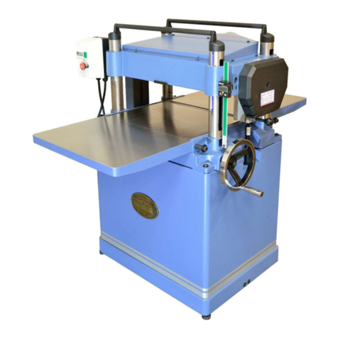
Oliver 0015 User manual

Model 0015
HS 15” Planer
Owner’s Manual
Oliver Machinery M-0015HS 08/2015
Seattle, WA Copyright 2003-2015

1
Table of Contents Page
For Your Own Safety Read Instruction Manual Before Operating This Tool ........................2
PLACEMENT THE 15” PLANER..........................................................................................3
15” PLANER.........................................................................................................................4
UNPACKING AND CLEANING ............................................................................................4
MOVING THE PLANER ......................................................................................................4
ASSEMBLY..........................................................................................................................5
HELICAL CUTTERHEAD.....................................................................................................6
SAFETY SWITCH ................................................................................................................6
CONSTRUCTING GAUGE BLOCK .....................................................................................6
OPERATE............................................................................................................................7
ADJUSTMENT .....................................................................................................................8
PARTS LUBRICATION REQUIRED ..................................................................................13
CHANGE LUBRICANT ......................................................................................................13
TROUBLESHOOTING ....................................................................................................... 14
WIRING DIAGRAMS .........................................................................................................15
PARTS DIAGRAMS ........................................................................................................... 16
PARTS LIST....................................................................................................................... 19

2
For Your Own Safety Read Instruction Manual Before Operating This Tool
Read this manual completely and observe all warning labels on the machine. This machine has
made every attempt to provide a safe, reliable, easy-to-use piece of machinery. Safety, however,
is ultimately the responsibility of the individual machine operator. As with any piece of machinery,
the operator must exercise caution, patience, and common sense to safely run the machine.
Before operating this product, become familiar with the safety rules in the following sections.
1. KEEP WORK AREA CLEAN. Cluttered areas and benches invite accidents.
2. DON'T USE IN DANGEROUS ENVIRONMENT. Don't use power tools in damp or wet locations,
or expose them to rain. Keep work area well lighted.
3. KEEP CHILDREN AWAY. All visitors should be kept safe distance from work area.
4. MAKE WORKSHOP KID PROOF with padlocks, master switches, or by removing starter keys.
5. USE RIGHT TOOL Don't force tool or attachment to do a job for which it was not designed.
6. WEAR PROPER APPAREL Do not wear loose clothing, gloves, neckties, rings, bracelets, or
other jewelry which may get caught in moving parts. Nonslip footwear is recommended. Wear
protective hair covering to contain long hair.
7. ALWAYS USE SAFETY GLASSES. Also use face or dust mask if cutting operation is dusty.
Everyday eyeglasses only have impact resistant lenses, they are NOT safety glasses.
8. SECURE WORK. Use clamps or a vise to hold work when practical. It's safer than using your
hand and it frees both hands to operate tool.
9. DON'T OVERREACH. Keep proper footing and balance at all times.
10. MAINTAIN TOOLS WITH CARE. Keep tools sharp and clean for best and safest performance.
Follow instructions for lubricating and changing accessories.
11. REDUCE THE RISK OF UNINTENTIONAL STARTING. Make sure switch is in off position
before plugging in.
12. USE RECOMMENDED ACCESSORIES. Consult the owner's manual for recommended
accessories. The use of improper accessories may cause risk of injury to persons.
13. CHECK DAMAGED PARTS. Before further use of the tool, a guard or other part that is
damaged should be carefully checked to determine that it will operate properly and perform its
intended function - check for alignment of moving parts, binding of moving parts, breakage of
parts, mounting, and any other conditions that may affect its operation.
A guard or other part that is damaged should be properly repaired or replaced.
14. DIRECTION OF FEED. Feed work into a blade or cutter against the direction of rotation of the
blade or cutter only.
15. NEVER LEAVE TOOL RUNNING UNATTENDED. TURN POWER OFF. Don't leave tool until it
comes to a complete stop.
16. Wear eye protection.

3
17. KEEP GUARDS IN PLACE and in working order.
18. REMOVE ADJUSTING KEYS AND WRENCHES. Form habit of checking to see that keys and
adjusting wrenches are removed from tool before turning it on.
19. DON'T FORCE TOOL It will do the job better and safer at the rate for which it was designed.
20. DISCONNECT TOOLS before servicing; when changing accessories, such as blades, bits,
cutters, and the like.
21. NEVER STAND ON TOOL. Serious injury could occur if the tool is tipped or if the cutting tool is
unintentionally contacted.
Your risk from these exposures varies, depending on how often you do this type of work. To
reduce your exposure to these chemicals, work in a well-ventilated area, and work with
approved safety equipment, such as those dust masks that are specifically designed to filter out
microscopic particles.
Familiarize yourself with the following safety notices used in this manual:
CAUTION: (This means that if precautions are not heeded, it may result in minor or moderate
injury and/or possible machine damage)
WARNING: (This means that if precautions are not heeded, it could result in serious injury or
possibly even death).
PLACEMENT THE 15”PLANER
This machine should be installed and operated only on a solid, flat and stable floor that is able to
support the weight of the planer (430 lbs-195kgs) and the operator.
Using the dimensions shown as below (L1600mmx694.7mmx1330.6mm), plan for placement within
your shop that will allow the operator to work unencumbered and unobstructed by foot traffic or
other tools or machinery.

4
15” PLANER
Thank you for choosing this planer.
This unit is carefully tested and inspected before
shipment and if properly used and maintained, will
provide you with 1 year of reliable service. To
ensure optimum performance and trouble free
operation a reasonable amount of care and
attention is required.
To get the most from your new planer, please take
the time to read this manual before assembling,
installing and operating the unit.
UNPACKING AND CLEANING
To ensure maximum performance from your 15"
planer, clean it properly; and install it accurately
before use. As soon as you receive the planer, we
recommend you follow these procedures:
1. Finish removing the contents of the shipping
carton and compare with the contents list.
2. Report damage, if any to your local distributor.
3. Clean all rust protected surfaces with a mild
solvent or kerosene. Do not use lacquer thinner;
paint thinner, or gasoline. These will damage
painted surfaces.
4. To prevent rust, apply a light coating of paste
wax to surface.
USING A SLING
Please using a sling to carry machine, lifting
handles must be pulled out (Fig.1). Try keeping
sling parallel to machine and hold steady.
MOVING THE PLANER
There are two castors provided at the front bottom
and one caster in rear of the enclosed type stand
for easy movement of the planer.
When moving the planer is required step on the
foot pedal to slightly raise the machine and
conveniently move it. Once the planer has been
moved to its desired location, shift the foot pedal
upward to allow the leveling screws to rest on the
floor for planer stability.
Fig. 1
Fig. 2
STOP
MOVEABLE

5
ASSEMBLY
ASSEMBLY DUST CHUTE
Mount the dust chute to the planer hood with 3 Hex.
head screws w/washer (A) . CAP screws (B) &
spring washers (C), Fig. 3.
Make sure the dust collection system has
sufficient capacity and suction for your planer.
Note: Always turn on the dust collection system
before starting the planer.
ASSEMBLY HANDWHEEL
1. Installed the handwheel (D) onto the top of
elevation screw (E) , Fig. 4
2. Put the instruction label , flat washer on the
top of handwheel then using the Hex. Nut (F)
to lock the handwheel.
3. Installed the handle (I) on the handwheel
ASSEMBLY EXTENSION TABLE
1. The extension tables are mounted at the front
and rear ends of the main table.
2. Press the lock pin (I) to release the support leg.
3. Put the support leg into the fix bracket (K) on the
stand, Fig. 5.
4. To raise or lower the extension table.
5. Raise the cυtterhead by handwheel handle (I,
Fig. 4) so thot you can get a clear view and
work comfortably when making adjustment.
6. Place a straight edge (N) across the main table
and the extension tables to be adjusted, Fig. 6.
7. If the extension tables are not leveled,then
adjust them applying 17mm open end wrench to
loosen nut (L, Fig. 5) and turn the adjustment
screw (M) until the extension tables near the
main table end just touches the straight edge.
Then adjust the leveling of the other end of the
extension tables by turning the adjustment
screw, located on the extension tables support.
Adjust the right and left side of the extension
tables in this way, Fig.5.
8. Use the same method for both the front and rear
extension table.
WARNING: Disconnect the machine from the power
source.
Fig. 3
Fig. 4
Fig. 3
Fig. 5
Fig. 6
A
C
B
D
I
F
G
H
E
J
K
L
M
N

6
HELICAL CUTTERHEAD
Knife inserts are dangerously sharp. Use extreme
caution when inspecting, removing, or replacing
knife inserts.
The knife inserts on the Jointer are four-sided.
When dull, simply remove each insert, rotate it 90°
for a fresh edge, and re-install it. No further
adjustment is necessary. Use the two provided torx
wrench to remove the knife insert screw. Use one
of the torx wrenches to help hold the cutterhead in
Position, and the other to remove the screw. See
Fig. 7. It is advisable to rotate all inserts at the
same time to maintain consistent cutting. However,
if one or more knife inserts develops a nick, rotate
only those inserts that are affected.
Each knife insert has an etched reference mark so
you can keep track of the rotations.
IMPORTANT: When removing or rotating inserts,
clean saw dust from the screw, the insert, and the
cutterhead platform. Dust accumulation between
these elements can prevent the insert from seating
properly, and may affect the quality of the cut.
Before installing each screw, lightly coat the screw
threads with machine oil and wipe off any excess.
Securely tighten each screw which holds the knife
inserts before operating the jointer!
Make sure all knife insert screws are tightened
securely. Loose inserts can be propelled at high
speed from a rotating cutterhead, causing injury.
from a rotating cutterhead, causing injury.
Fig. 7
SAFETY SWITCH
The planer is equipped with a push-button switch
that will accept a safety padlock (not included).
See Fig. 8.
To safeguard your machine from unauthorized
operation and accidental starting by young children,
the use of a padlock is required.
Fig. 8
CONSTRUCTING GAUGE BLOCK
Before starting any adjustments, disconnect the
machine from the power source.
The manufacturer has adjusted all machines
before delivery.
Verify that the screws are properly tightened.
The only time you will have to adjust your machine
is when it has been functioning for a long time. The
adjustment will have to be made to adjust the
precision of the machine.
- Straight scale
- Thickness gauge
- Home made gauge block of hard wood, with the
dimensions as shown in Fig. 9
Fig. 9
7
OPERATE
DEPTH OF CUT ADJUSTMENT
Turn the handwheel (B) on a clockwise or counter-
clockwise direction to the proper height, Fig. 10.
The depth of cυt on your planer is controlled by
raising or lowering the head assembly shown in
Fig. 10,which contains the cutterhead and feed
roller. The head assembly raises and lowers on
four precision steel ground columns. To adjust for
depth of cut, simply loosen the two head assembly
lock knobs (A), and turn the handwheel (B).
After the desired depth of cut is obtained, tighten
the lock knobs (A) combination inch/metric scale (C)
is conveniently located on the right front column for
easy reading. The maximum depth of cυt on full
width planning is 1/8" (3.175mm) .
A limiter (D) is provided on single phase machines
to limit the depth of cut. If the workpiece to be cut is
less than 6", the allowable maximυm depth of cut
is no more than 6mm in one pass, Fig. 10
Warning: Never over the cutting limited,
15“~6”width........... 3mm
Under 6”width........ 6mm
ANTI-KICKBACK FINGERS
Anti-kickback fingers (E) are provided on your
planer to prevent kickback. These fingers operate
by gravity and it is necessary to inspect them
occasionally to make sure they are free of gum and
pitch so that they move independently and operate
correctly, Fig.11
FEED ROLL SPEED CONTROL
Your machine is equipped with a spiral, serrated
infeed roller and a solid steel outfeed roller.
When the feed rollers are engaged, they turn and
feed the stock. The feed rollers slow automatically
when the machine is under heavy load for best
planning under all conditions. The feed rollers are
driven by a chain and sprocket drive, which takes
power directly from the cutterhead through the oil
bath gearbox. To engage the feed rollers, pull out
the lever (F), Fig. 12. To disengage the feed rollers
push in the lever. To change the feed speed, push
in the lever for 20 FPM or pull the lever out for 16
FPM. Set the lever in the neutral position for zero
speed.
Warning: The feed speed should only be changed
when the machine is running.(Fig.12)
Fig.10
Fig.11
Fig.12
B
A
C
D
E
F

8
ADJUSTMENT
Although your planer was carefully adjusted at the
factory, it should be checked before being put into
operation. Any inaccuracies due to rough handling
in transit can easily be corrected by following these
directions:
In order to check the adjustments you will need a
straight edge, feeler gauge and a homemade
gauge block made of hardwood. This gauge block
can be made by the dimensions showing in Fig. 13
Warning: WHEN CHECKING ADJUSTMENTS,
ALWAYS MAKE SURE THE PLANER IS
DISCONNECTED FROM THE POWER SOURCE
ADJUSTING BELT TENSION
To adjust the belt tension on your machine,
proceed as follows:
1. Disconnect the machine from the power source.
2. Remove pulley cover from the machine.
3. Place a board (A) underneath the motor base
(B, Fig. 14)
4. Loosen the two bolts (C, Fig. 15) and
micrometric adjustment screw (D) by shifting it
to the highest position of the slot (E), and pry up
on the motor base to an approximate belt
tension. Then make micrometric adjustment of
belt tension. At this time, loosen the micrometric
adjustment screw to the highest position of the
slot (E). Adjust belt tension until correct belt
tension is obtained.
5. Correct tension is obtained when there is
approximately 1/4" deflection in the center span
of the belts using light finger pressure.
6. Then tighten two bolts and remount pulley cover.
(Fig.15)
Fig. 13
Fig. 14
Fig. 15
Fig. 14
Fig. 15
A
B
D
C
E

9
ADJUSTING FEED ROLL SPRING TENSION
The infeed roller (A) and outfeed roller (B) are
those parts of your planer that feed the stock while
it is being planned. The feed rolls (A) and (B) are
under spring tension and this tension must be
sufficient to feed the stock uniformly through the
planer without slipping, but should not be so tight
that it causes damage to the board. The tension
should be equal at both ends of each roller. (Fig.
16)
To adjust the spring tension of the infeed roller,
turn screw (C) and also the screw shown on the
opposite end of planer.
To adjust the spring tension of the outfeed roller,
turn screw (D) and also the screw on the opposite
end of the planer.(Fig. 17)
ADJUSTING TABLE ROLLS
This planer is supplied with two table rollers (E, Fig.
18) which aid in feeding stock by reducing friction,
and turn as the stock is fed through the planer.
It is not possible to give exact dimensions on the
proper height setting of the table rollers.
Because each type of wood behaves differently.
As a general rule, however,when planning rough
stock the table rollers should be set HIGH and
when planning smooth stock the table rollers
should be set at LOW. In general,the suggested
table roll height is at least 0.5mm over the table
surface.
The table rollers on your planer are set for average
planning and are parallel to the table surface. If you
desire to adjust the rolls higher or lower,proceed
as follows:
1. Disconnect the machine from the power source.
2. Lay a straight edge (G, Fig. 19) across both
rollers. Loosen the screw (F, Fig. 18), then turn
the two eccentric shafts (H, Fig. 18) to raise or
lower table rollers. Table rolls must also be
adjusted on the opposite end of the table in the
same manner. The table rollers must always be
set parallel to the table.
Warning: Disconnect the machine before
performing any adjustments. Failure to comply
can cause serious injuries to the machine and
the work operator.
Fig. 16
Fig. 17
Fig. 18
Fig. 19
C
D
A
B
E
H
F
G

10
ADJUSTING HEIGHT OF INFEED ROLLER &
OUT FEED ROLLER
The outfeed roller is adjusted at the factory be set
0.5mm below the cutting circle. To check and
adjust the outfeed roller, proceed as follows:
1. Disconnect machine from the power source.
2. Make sure the knives are adjusted properly as
explained under CHECKING,ADJUSTING AND
REPLACING KNIVES.
3. Place the gauge block on the table directly
underneath the cutterhead as Fig. 20. Using a
0.5mm feeler gauge (B),placed on top of the
gauge Block (C), raise or lower the head until
the knife tip just touches the feeler gauge when
the knife is at its lowest point. Do not move the
head any further until the outfeed roller is
adjusted.
1. Move the gauge block (C) under on end of the
infeed roller (D, Fig. 21). Using a 0.5mm feeler
gauge (A). The bottom of the infeed roller
should just touch the feeler gauge (B). If an
adjustment to the infeed roller is necessary;
loosen locknut (E) and turn screw (F) until the
infeed roller just touches the gauge block. Then
tighten the locknut (E).
5. Move the gauge block (C) under on end of the
outfeed roller (G, Fig. 22). Using a 0.5mm feeler
gauge (A). The bottom of the outfeed roller
should just touch the feeler gauge (B). If an
adjustment to the outfeed roller is necessary;
loosen locknut (H) and turn screw (I) until the
outfeed roller just touches the gauge block. Then
tighten the locknut (H).
Fig. 20
Fig. 21
Fig. 22
B
A
C
A
C
B
E
F
D
C
B
G
I
H

11
ADJUSTING CHIP BREAKER
The chip breaker is located on top of the planer
and extends down around the front of the
cutterhead. The chip breaker raise as stock is fed
through and "breaks or curls" the chips the same
as a plane iron cap on a hand plane.
The bottom of the chip breaker must be parallel to
cutting circle. To check and adjust the chip breaker,
proceed as follows:
1. Disconnect the machine from the power source.
2. Make certain the knives are adjusted properly
as previously explained under CHECKING,
ADJUSTING AND REPLACING KNIVES.
3. Place the gauge block (A) on the table directly
underneath the cutterhead as shown. Using a
0.5mm feeler gauge (B), placed on top of the
gauge block, raise or lower the head until the
knife tip (C) jυsf touch the feeler gauge when
the knife is at its lowest point. Do not move the
head any further until the chip breaker is
checked and adjusted as necessary, Fig. 23.
4. Move the gauge block (C) underneath the chip
breaker (D, Fig. 24). The bottom of the chip
breaker should just touch the top of the gauge
block. Check the opposite end of the chip
breaker in the same manner.
5. If an adjustment to the chip breaker is
necessary, loosen nuts (E, Fig. 25) , and turn
screws (F) until the bottom of the chip breaker
just touches the gauge block. Then tighten the
nuts (E).
Fig. 23
Fig. 24
Fig. 25
B
A
C
A
E
F
C
D

12
ADJUSTING CUTTERHEAD PARALLEL TO
TABLE
The cutterhead is set paraIlel to the table at the
factory and no further adjustment should be
required. If your machine is planing a taper,first
check to see if the knives are set properly in the
cutterhead. Then check to see if the table is set
parallel to the cutterhead as follows:
1. Disconnect the machine from the power source.
2. Place gauge block (C) on table directly under
cutterhead, Fig. 26. Lower cutterhead until knife
tip just touches gauge block.
3. Move gauge block (C) to opposite end of table
Fig. 27.
4. Repeat steps 2 and 3 on outfeed end of table.
2. If cutterhead is not parallel to table, tilt planer on
its side, Fig. 28. Remove bolt (H) and loosen
bolt (I), which will allow you to move the idler
sprocket far enough to release tension on the
chain, Fig. 29. Remove chain from sprocket on
end of cυtterhead that must be adjusted. ln this
case chain has been removed from sprocket.
3. Turn sprocket (G, Fig. 28) by hand to bring that
corner into adjusfment with other three corners.
IMPORTANT: THIS ADJUSTMENT IS VERY
SENSITIVE AND IT SHOULD NOT BE
NECESSERY TO TURN THE SPROCKET
MORE THAN ONE OR TWO TO TURN THE
SPROCKET MORE THAN ONE OR TWO
TEETH.
Turning sprocket clockwise will decrease the
distance between the table and cutterhead.
Counter-clockwise will increase the distance.
Fig. 26
Fig. 27
Fig. 28
Fig. 29
H
I
G
C
C

13
PARTS LUBRICATION REQUIRED
NO.
POSITION
GREASE
OIL
1
GEAR BOX
NO
YES
2
CHAIN
YES
NO
3
CHAIN
YES
NO
4
CHAIN
YES
NO
5
BRACKET
NO
YES
6
LEAD SCREW
YES
NO
7
COLUMN CLEAN & OIL
NO
YES
- Worm Gear is used to adjust the table up or down.
- The oil in Gear Box must be changed after 2500
hours of work.
- All chains must be lubricated regularly.
- After 30 hours or more of work the lubrication of
bracket must be changed.
- The machine comes equipped with four head
screws, it is important to always keep them
lubricated.
- To ensure maximum performance always keep
the sliding rolls of table lubricated
CHANGE LUBRICANT
When lubrication needs to be changed:
1. Loosen the nut A on the outfeed hole.
2. Clean out old lubrication and let it dry.
3. Tighten nut A
4. Replace clean lubricant by hole B
2
3
1
4
5
5
6
7
A
B

14
TROUBLESHOOTING
PROBLEM
POSSIBLE CAUSE
REMEDY
FUZZY GRAIN
1. Planning wood with high moisture
content
2. Dull knives
1. Dry the wood
2. Sharpen knives
TORN GRAIN
1. Too heavy a cut
2. Knives cutting against the grain
3. DUII knives
1. Review proper depth
2. Feed wood with the grain, or turn
workpiece around
3. Sharpen knives
ROUGH/RAISED GRAIN
1. Dull knives
2. Too heavy a cut
3. Moisture content to high
4. Cutterhead bearings damaged
1. Sharpen knives
2. Review proper
3. Dry the wood
4. Replace bearings
POOR FEEDING OF LUMBER
1. Planer table dirty
2. Feed roller damaged.
3. Sprocket damaged
4. Gearbox malfunction
1. Clean off pitch and residue, and
lubricate planer table.
2. Replace
3. Replace
4. Check gearbox
WORKPIECE JAMMED
1. Inadequate knife setting height
1. Set knives to the correct height
UNEVEN DEPTH OF CUT SIDE
TO SIDE
1. Knife projection not uniform
2. Cutterhead not leveled to planer
bed
1. Adjust knife projection
2. Level cutterhead t table
BOARD THICKNESS DOESNT
MATCH DEPTH OF CUT SCALE
1. Depth of cut scale incorrect
1. Adjust depth of cut scale
CHAIN JUMPING
1. Sprockets misaligned
2. Sprockets worn
1. Align sprockets
2. Replace sprockets
MECHANICAL/ ELECTRICAL
MACHINE WON'T
START/RESTART
1. Not plugged in
2. Circuit breaker / fuse
3. Motor failure
4. Loose wire
5. Overload reset has not reset
6.Motor starter failure
1. Check power source
2. Have motor checked by qualified
technician
5. AII machine to cool down and restart
6. Have motor starter checked by
qualified electrician
REPEATED CIRCUIT TRIPPING
RESULTING IN MOTOR
STOPPAGE
1. Extension cord too long or too thin
2. Knives too dull
3. Low voltage running
1. Use a shorter or thicker extension
cord
2. Sharpen or replace knives
3. Check voltage

15
WIRING DIAGRAMS

16
PARTS DIAGRAMS

17

18

19
PARTS LIST
Key
Part No.
Descriptions
Q'ty
1
170404-000
BELT COVER
1
2
014001-000
V-BELT
M27
3
3
000003-104
HEX. SCREW
M8*1.25P*20
4
4
000004-103
HEX. SCREW
M10*1.5P*30
3
5
006001-043
FLAT WASHER
8.2*30*4.0t
1
6
006001-082
FLAT WASHER
10.5*28*3.0t
3
7
050273-000
CUTTERHEAD PULLEY
1
8
050272-000
BELT GUARD FRONT
1
9
012003-003
KEY
5*5*12
1
10
901010-000
MOTOR ASSY
3HP*1PH
1
12
000004-108
HEX. SCREW
M10*1.5P*80
1
13
000902-102
HEX SCREW W/WASHER
M6*1.0P*12
24
14
190073-901
BUSHING
1
15
000003-105
HEX. SCREW
M8*1.25P*25
6
16
922360-000
DUST HOOD ASSEMBLY
1
17
08006-100
HEX. NUT
8
19
050274-000
MOTOR PLATE
1
20
006001-056
FLAT WASHER
8.5*23*2.0t
16
21
000003-108
HEX. SCREW
M8*1.25P*40
4
22
006001-041
FLAT WASHER
8.2*22*3.0t
3
23
170405-901
BRACKET
1
24
290039-901
SHAFT
1
25
130071-000
CHAIN TENSIONER
1
26
360349-901
CHAIN TENSIONER SHAFT
1
27
280050-000
SPRING
1
28
170406-901
HOOK
1
29
000103-102
CAP SCREW
M6*1.0P*10
2
30
008008-100
HEX NUT
M10*1.25P
4
31
006001-067
FLAT WASHER
8.5*16*1.5t
4
33
920349-000
HANDWHEEL ASSY
1
33.1
240014-000
HAND WHEEL
1
33.2.1
008008-200
HEX NUT
M10*1.25P
1
33.2.2
006002-067
FLAT WASHER
10*20*1.5t
1
33.2.3
570887-000
INDICATOR LABEL
1
34
230114-906
HANDLE
1
35.1
170419-000
TOP COVER
1
35.2
170410-019
CHIP BREAKER
1
36
250158-617
CHIP DEFLECTOR
1
37
250159-615
PLUG
3
38
000104-114
CAP SCREW
M8*1.25P*50
4
39
230115-000
KNOB
1
40
130037-000
LOCK KNOB
2
41
000002-101
HEX. SCREW
M6*1.0P*12
4
42
050275-000
HEAD CASTING
1
43
270015-901
SPRING PLATE
3
Table of contents
Other Oliver Planer manuals

Oliver
Oliver 4470 User manual

Oliver
Oliver 5240 User manual

Oliver
Oliver 4430 User manual

Oliver
Oliver 4455 User manual

Oliver
Oliver 4455 User manual

Oliver
Oliver 4420 User manual

Oliver
Oliver 5235 User manual

Oliver
Oliver 4430.201 M-4430 User manual

Oliver
Oliver 4420 User manual

Oliver
Oliver 10014 User manual