Oliver 4455 User manual

4455 Professional Planer 20”
Owner’s Manual
Oliver Machinery M-4455 12/2017
Seattle, WA Copyright 2003-2017

2
Warranty
Oliver makes every effort possible to assure that its equipment meets the highest possible standards of
quality and durability. All products sold by Oliver are warranted to the original customer to be free from
defects for a period of 2 (two) years on all parts, excluding electronics and motors, which are warranted
for 1 year. Oliver’s obligation under this warranty shall be exclusively limited to repairing or replacing (at
Oliver’s option) products which are determined by Oliver to be defective upon delivery F.O.B. (return
freight paid by customer) to Oliver, and on inspection by Oliver. This warranty does not apply to defects
due, directly or indirectly, to misuse, abuse, negligence, accidents, unauthorized repairs, alterations, lack
of maintenance, acts of nature, or items that would normally be consumed or require replacement due to
normal wear. In no event shall Oliver be liable for death, personal or property injury, or damages arising
from the use of its products.
Warning
Read this manual thoroughly before operating the machine. Oliver Machinery disclaims any liability for
machines that have been altered or abused. Oliver Machinery reserves the right to effect at any time,
without prior notice, those alterations to parts, fittings, and accessory equipment which they may deem
necessary for any reason whatsoever.
For More Information
Oliver Machinery is always adding new Industrial Woodworking products to the line. For complete, up-to-
date product information, check with your local Oliver Machinery distributor, or visit
www.olivermachinery.net

3
WARNING
Read this manual completely and observe all warning labels on the machine. Oliver Machinery has made
every attempt to provide a safe, reliable, easy-to-use piece of machinery. Safety, however, is ultimately
the responsibility of the individual machine operator. As with any piece of machinery, the operator must
exercise caution, patience, and common sense to safely run the machine. Before operating this product,
become familiar with the safety rules in the following sections.
Always keep guards and covers in place and in proper operating condition.
1. If you are not properly trained in the use of a planer do not use until the proper training has been
obtained.
2. Read, understand and follow the safety instructions found in this manual. Know the limitations and
hazards associated with this machine.
3. Make certain that the machine frame is electrically grounded and that a ground lead is included in the
incoming electrical service. In cases where a cord and plug are used, make certain that the
grounding plug connects to a suitable ground. Follow the grounding procedure indicated in the
National Electrical Code.
4. Wear an approved safety shield, goggles, or glasses to protect eyes. Common eyeglasses are only
impact-resistant, they are not safety glasses.
5. Before operating the machine, remove tie, rings, watch and other jewelry and roll up sleeves above
the elbows. Remove all loose outer clothing and confine long hair. Protective type footwear should
be used. Where the noise exceeds the level of exposure allowed in Section 1910.95 of the OSHA
Regulations, use hearing protective devices. Do not wear gloves.
6. Keep the machine guards and covers in place for every operation. If any guards and covers are
removed for maintenance, DO NOT OPERATE the machine until the guards and covers are
reinstalled.
7. Keep the floor around the machine clean and free of scrap material, saw dust, oil and other liquids to
minimize the danger of tripping or slipping. Be sure the table is free of all scrap, foreign material and
tools before starting the planer. Make certain the work area is well lighted and that a proper exhaust
system is used to minimize dust. Use anti-skid floor strips on the floor area where the operator
normally stands and mark off machine work area. Provide adequate work space around the machine.
8. Maintain a balanced stance and keep your body under control at all times.
9. Before turning on machine, remove all extra equipment such as keys, wrenches, scraps, and cleaning
rags away from the machine.
10. Give the work you are doing your undivided attention. Looking around, carrying on a conversation,
and “horseplay” are careless acts that can result in serious injury.
11. Before performing any service, maintenance, adjustments or when changing knives disconnect the
machine from power source. A machine under repair should be RED TAGGED to show it should not
be used until the maintenance is complete.

4
12. Do not plane boards with loose knots, nails or any foreign material in the workpiece. Irregular, or
warped stock should be jointed first on one side before planing a parallel surface.
13. If the operator leaves the machine area for any reason, the planer should be turned "off" and the
cutterhead should come to a complete stop before their departure. In addition, if the operation is
complete, they should clean the planer and the work area. NEVER clean the planer with power "on"
and never use hands to clear sawdust and debris; use a brush or air hose.
14. Use only genuine Oliver Machinery factory authorized replacement parts and accessories; otherwise
the warranty and guarantee is null and void.
15. Do not use this Oliver planer for other than its intended use. If used for other purposes, Oliver
disclaims any real or implied warranty and holds itself harmless for any injury or damage which may
result from that use.
16. Do not operate this machine while under the influence of drugs, alcohol, or any medication.
17. This machine is deigned for planing wood products only. Do not use to plane any kind of substance
other then wood.
18. Never start the planer while a workpiece is in contact with the cutterhead or knives.
19. Always feed workpiece against the rotation of the cutterhead.
20. Some dust created by power sanding, sawing, grinding, drilling and other construction activities
contains chemicals known to cause cancer, birth defects or other reproductive harm. Some examples
of these chemicals are:
Lead from lead-based paint.
Crystalline silica from bricks and cement and other masonry products.
Arsenic and chromium from chemically-treated lumber.
Your risk from these exposures varies, depending on how often you do this type of work. To reduce
your exposure to these chemicals, work in a well-ventilated area, and work with approved safety
equipment, such as those dust masks that are specifically designed to filter out microscopic particles.
Familiarize yourself with the following safety notices used in this manual:
CAUTION: (This means that if precautions are not heeded, it may result in minor or moderate injury
and/or possible machine damage)
WARNING: (This means that if precautions are not heeded, it could result in serious injury or possibly
even death).

5
Table of Contents Page Number
Warranty ........................................................................................................................................................ 2
Warnings .................................................................................................................................................... 3-4
Table of Contents .......................................................................................................................................... 5
Specifications ................................................................................................................................................ 5
Contents of the Shipping Container .............................................................................................................. 6
Uncrating the Machine .................................................................................................................................. 6
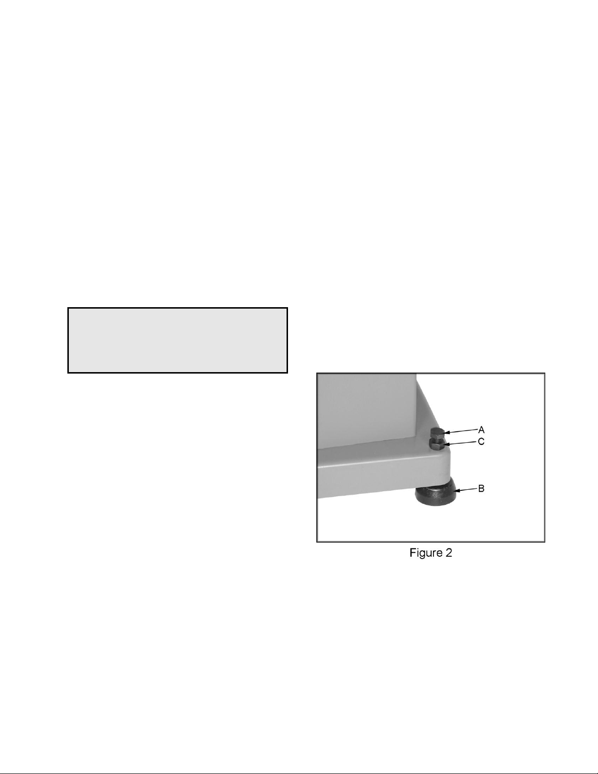
Machine Preparation and Setup ................................................................................................................... 6
Electrical Connections ................................................................................................................................... 7
Assembly ....................................................................................................................................................... 8
Control Panel ................................................................................................................................................ 8
Changing Feed Rate ..................................................................................................................................... 8
Table Roller Adjustment ................................................................................................................................ 8
Raising and Lowering Table.......................................................................................................................... 9
Table Stop ..................................................................................................................................................... 9
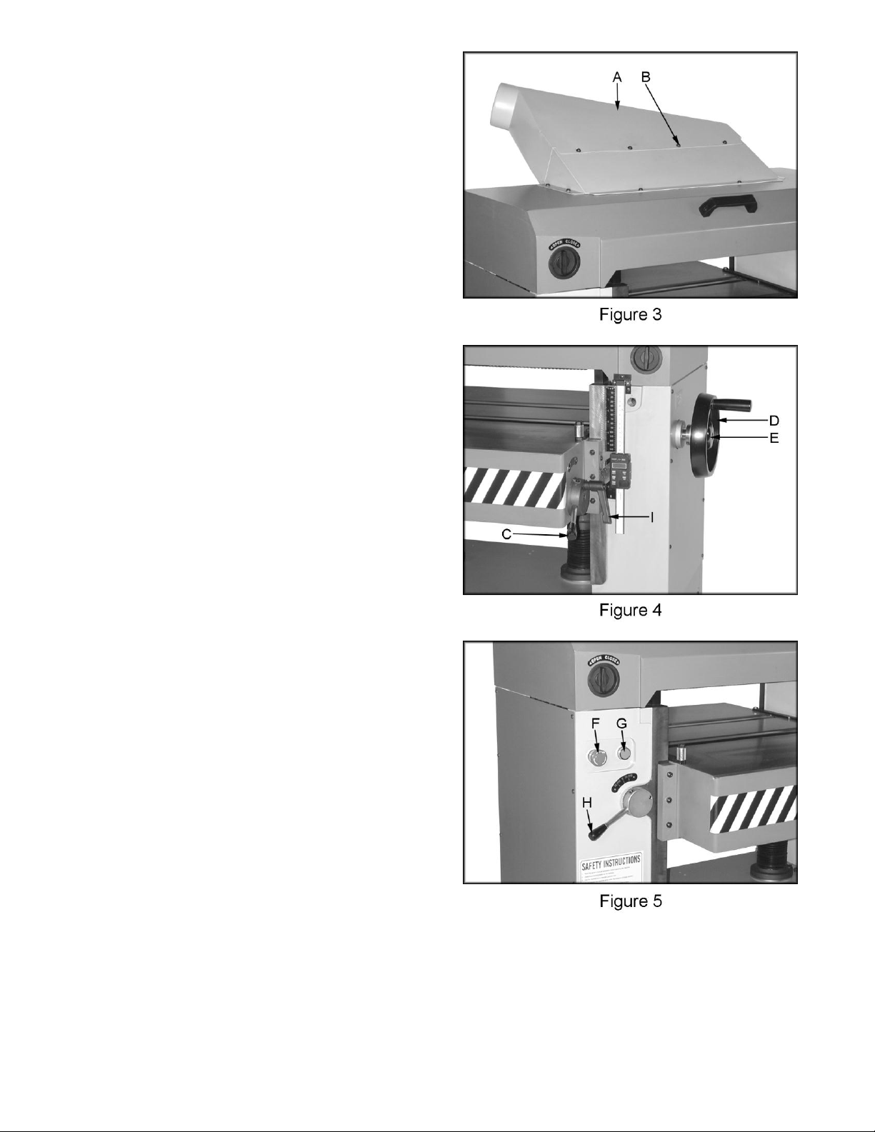
Opening Hood ............................................................................................................................................... 9
Calibrating the Thickness Scale .................................................................................................................... 9
Digital Readout ............................................................................................................................................ 10
Setting / Changing Knives ........................................................................................................................... 11
Helical Cutterhead Option ........................................................................................................................... 12
Setup of Feed Rollers, Chipbreaker and Pressure Bar .............................................................................. 13
Anti-Kickback Fingers ........................................................................................................................... 14
Adjustment of In-Feed Roller ................................................................................................................ 14
Adjustment of Chipbreaker ................................................................................................................... 14
Adjustment of Pressure Bar .................................................................................................................. 15
Adjustment of Out-feed Roller .............................................................................................................. 15
Helical Cutterhead ....................................................................................................................................... 16
V-Belt Adjustment ....................................................................................................................................... 16
Adjusting Table Gibs ................................................................................................................................... 16
Adjusting Table Rollers ............................................................................................................................... 17
Maintenance ................................................................................................................................................ 17
Lubrication ................................................................................................................................................... 18
Troubleshooting .......................................................................................................................................... 19
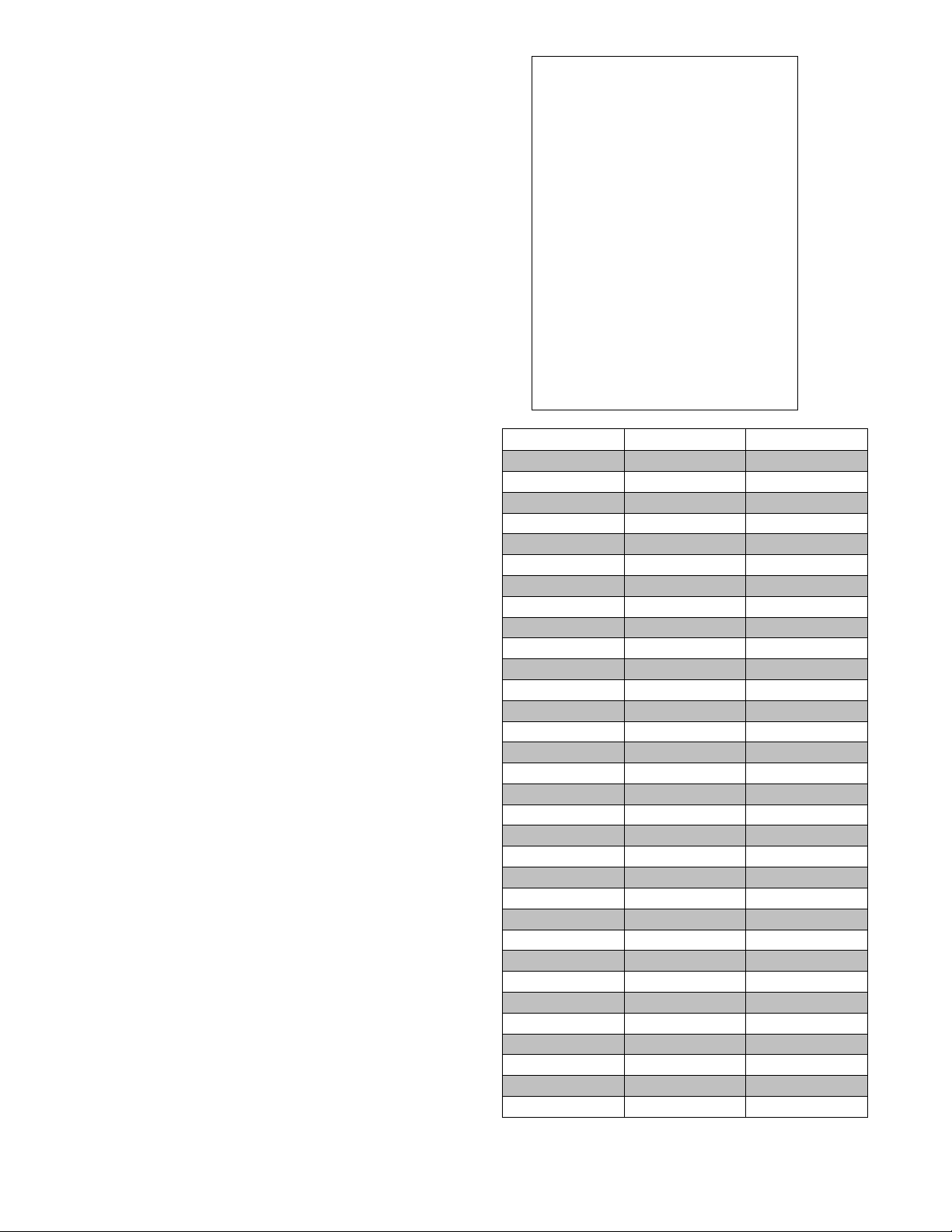
Specifications
Stock No. ..................................................................................... (7.5HP, 1Ph HSS Straight Knife) 4455.001
Stock No. ..................................................................................... (7.5HP, 3Ph HSS Straight Knife) 4455.002
Stock No. ........................................................................ (7.5HP, 1Ph Carbide Helical Cutterhead) 4455.101
Stock No. ........................................................................ (7.5HP, 3Ph Carbide Helical Cutterhead) 4455.102
Maximum Stock Width (in.) ......................................................................................................................... 22
Maximum Depth of Cut (in.) ..................................................................................................................... 3/16
Maximum Stock Thickness (in.) .................................................................................................................... 9
Minimum Stock Thickness (in.) .................................................................................................................. 1/8
Minimum Stock Length (in.) ........................................................................................................................ 10
Dust Port Diameter (in.) ................................................................................................................................ 5
Minimum CFM Required ........................................................................................................................... 900
Segmented Infeed Roller Diameter (in.) ....................................................................................................... 3
Outfeed Roller Diameter (in.) ........................................................................................................................ 3
Feed Speeds (FPM) ........................................................................................................................ 20 and 30
Bed Rollers ................................................................................................................................. 2, Adjustable
Table Size (L x W/in.) .............................................................................................................. 32-1/4 x 23-3/4
Cutterhead Diameter (in.) .............................................................................................................................. 3
Number of Knives .......................................................................................................................................... 4
Cutterhead Speed (RPM) ....................................................................................................................... 5,000
Table Support .................................................................................................................................. 2-Column
Motor .......................................................................................................................... 7.5HP, 1Ph, 220V Only
........................................................................................................ 7.5HP, 3Ph, 220V/440V, Prewired 220V
Gross Weight (lbs.) ................................................................................................................................ 1,568

6
Oliver 4455 - 20” Professional Planer
1. 20” Planer
Box 1
4. Leveling Pads
4. Hex Key Wrenches
4. Open End Wrenches
4. Leveling Bolts and Nuts
1. Knife Setting Gauge
2. Lifting Eye Bolts and Nuts
1. Knob for Handwheel
1. Handwheel
1. Handle
Box 2
1. Dust Chute
8. Hex Head Screws M6x10
Uncrating the Machine
Retain all packaging materials in case it
becomes necessary to ship the machine to
another site.
Machine Preparation and Setup
WARNING!
The equipment used to lift this machine must
have a rated capacity at, or above the weight
of the planer. Failure to comply may cause
serious injury!
The planer can be lifted from over head using
slings and the two lifting eye bolts (A, Figure 1).
There are two threaded holes for the eye bolts.
One is located in the right front corner and the
other is in left rear corner. Thread the eye bolt
into the hole at least half way and tighten the nut
(B, Figure 1).
Remove the eye bolts and save in case the
machine needs to be moved in the future.

7
Machine Preparation and Setup (cont’d)
Thread leveling bolts (A, Figure 2) into holes in
the four corners of the planer base. The planer
must be positioned on a smooth, level surface.
Install the leveling pads (B, Figure 2) under the
four corners of the planer.
Clean all rust protected surfaces with a
commercial solvent. Do not use acetone,
gasoline, lacquer thinner or any type of
flammable solvent, or a cleaner that may
damage paint. Cover cleaned surfaces with
WD-40 or a 20W machine oil.
Place a level on the table of planer and adjust
leveling bolts until the machine is resting level.
Tighten the hex nuts (C, Figure 2) against the
base of the planer to keep the leveling bolts from
turning.
Electrical Connections
WARNING!
Electrical connections and wiring must be
done by a qualified electrician. The machine
must be properly grounded. Failure to
comply may cause serious injury!
This planer is available in both 1-Phase and 3-
Phase versions.
Electrical Connections for a 3-Phase Unit
This planer is 3-Phase, 220V/440V pre-wired
220V. If you need to switch the planer from
220V to 440V have a qualified electrician make
the changes.
Make sure the voltage of your power supply
matches the specifications on the motor plate of
the machine.
1. Disconnect machine from power source!
2. Remove screws that secure the cover to
connection box.
3. Insert the power cable through strain relief,
and attach the wires to terminals.
4. Re-install connection box cover. With 3-
Phase power verify in-feed roller is rotating
in the correct direction. Lower table
completely. Connect planer to the power
source and push the “ON” button to start the
planer. Crouch down to view in-feed roller
from the front of machine. The top of in-feed
roller should be rotating down towards you
in such a manner that it would pull a piece of
wood into the planer. If it does not,
disconnect machine from power source and
reverse any two incoming power leads.
5. When wiring is completed, tape all power
box joints to keep out dust.
Electrical Connections for a 1-Phase Unit
This planer is 1-Phase, 220V only.
Make sure the voltage of your power supply
matches the specifications on the motor plate of
the machine.
1. Disconnect machine from power source!
2. Remove screws that secure the cover to
connection box.
3. Insert the power cable through strain relief,
and attach the wires to the terminals.
4. Re-install connection box cover.
5. When wiring is completed, tape all power
box joints to keep out dust.

8
Dust Chute Assembly
Mount the dust chute (A, Figure 3) to the planer
hood with eight M6x10 hex head screws (B,
Figure 3). Make sure the dust collection system
has sufficient capacity and suction for your
planer. Always turn on the dust collection
system before starting the planer.
Table Roller Handle Assembly
Thread the handle (C, Figure 4) into the hub.
Handwheel Assembly
Line up the key on handwheel shaft with the key
way in the handwheel. Slide the handwheel (D,
Figure 4) into place and secure with knob (E,
Figure 4).
Control Panel (figure 5)
F. Emergency Stop Button: Stops all
functions of machine, but the planer still has
power. To reset rotate switch clockwise until
the button pops out.
G. Main Motor: Starts rotation of cutterhead.
Will not work if the “Emergency Stop” switch
is engaged, or hood is open.
Changing Feed Rate
The planer has two selectable feed speeds that
feed stock at 20 and 30 feet per minute. To
adjust speed, move lever (H, Figure 5) until it
clicks into place. Change feed speed only
while the feed system is RUNNING!
Table Roller Adjustment
Loosen the handle (I, Figure 4) and move the
table rollers up, or down by raising, or lowering
the handle (C, Figure 4). When you reach the
desired position tighten the handle.
The rollers are usually set higher when planing
rough stock. When planing smooth stock the
table rollers should be set slightly above, or flush
with the table.

9
Raising and Lowering Table
Turn the handwheel (A, Figure 6) clockwise to
raise the table. One revolution equals 1/16”.
Table Stop
The socket head cap screw (B, Figure 6) acts as
a stop and prevents you from running the table
into the cutting and feeding assembly.
Opening Hood
Turn the locks (C, Figure 6) clockwise to open
the hood. The hood will open automatically.
Use the handle (D, Figure, 6) to shut the hood.
Calibrating the Thickness Scale
The following sections will describe the use of a
calibrating board. The calibrating board should
be made of a hardwood and have one side that
has been run through a jointer.
1. With the planer turned “OFF – cutterhead
NOT spinning”, place your calibrating board
jointed surface down on the table and slide it
into the machine.
2. Use the handwheel (A, Figure 6) to raise the
table so that the in-feed roller is about 1/16"
above the calibrating board.
3. Remove calibrating board from planer and
turn the planer “ON”.
4. Turn the handwheel clockwise one complete
revolution to raise the table and run the
calibrating board through the planer.
5. Repeat Step 4 until the planer removes the
entire top surface of your calibrating board.
6. Measure the thickness of the board using a
pair of calipers.
7. Adjust the pointer (E, Figure 6) so that it
reads the measured thickness by loosening
the screw that holds it in place.

10
Digital Readout
The digital scale equipped with your 4455 ,22”
planer can serve many applications,however for
wood planing we need only concern ourselves
with the ON/OFF, SET, and mm/in buttons.
When set properly the digital readout will display
the thickness of the finished product.
Calibration: In order to calibrate the unit first
run a board through the planer and measure the
finished thickness with a set of vernier calipers.
This is the number to be entered into the display
unit. At this point turn the unit on by pushing the
ON/OFF button. Now press the mm/in button to
set the unit to American standard or the metric
system.
1. Press and hold the SET button until the ‘+’
sign starts to flash and immediately release
it.
2. Cycle the set button by pressing it until the
‘+’ sign remains on.
3. Press and hold the SET button until the
second zero to the right of the ‘+’ plus sign
starts to flash and immediately release it.
4. Cycle the SET button by pressing it until the
number reads the correct whole number
taken with the vernier calipers and
immediately release the button.
5. Press and hold the SET button until the zero
to the right of the decimal point starts to
flash.
6. Repeat steps 4 and 5 until the last digit in
the 0.001 place is entered.
7. Press and hold the SET button until the SET
on the display starts to flash and
immediately release it.
8. Press and release the SET button one final
time to complete the calibration.
Note: Do not turn the device off. If you do
you will have to re-calibrate the unit.
Battery: When the display begins to flash the
battery should be replaced. The battery is to be
replaced with a SR144 (or equivalent) and can
be found at most pharmacies or grocery stores.
When replacing the battery the positive side of
the button cell must face out.
A.
Fraction
Decimal
Metric
1/32
0.031
0.794
1/16
0.063
1.588
3/32
0.094
2.381
1/8
0.125
3.175
5/32
0.156
3.969
3/16
0.188
4.763
7/32
0.219
5.556
1/4
0.250
6.350
9/32
0.281
7.144
5/16
0.313
7.938
11/32
0.344
8.731
3/8
0.375
9.525
13/32
0.406
10.319
7/16
0.438
11.113
15/32
0.469
11.906
1/2
0.500
12.700
17/32
0.531
13.494
9/16
0.563
14.288
19/32
0.594
15.081
5/8
0.625
15.875
21/32
0.656
16.669
11/16
0.688
17.463
23/32
0.719
18.256
3/4
0.750
19.050
25/32
0.781
19.844
13/16
0.813
20.638
27/32
0.844
21.431
7/8
0.875
22.225
29/32
0.906
23.019
15/16
0.938
23.813
31/32
0.969
24.606
1
1.00
25.400

11
Setting / Changing Knives
WARNING!
Knives are extremely sharp. Be very careful
when handling knives. Failure to comply
may cause serious injury!
The Oliver 20” planer was designed to accept
22-1/8” x 1” x 1/8”) knives. Installing straight
knives accurately is an important step to achieve
a smooth finish. End to end, and knife to knife
adjustment must be accurate within .001". Use
a dial indicator if available to check results and
fine tune. Remove and replace the knife in one
slot before changing the next knife. Any knife
sharpening, or replacement should be done to
all four knives at the same time.
1. Disconnect machine from power source.
2. Open the hood, loosen eight locking bolts
(A, Figure 8) on the clamping block and
remove the knife. Remove and clean the
clamping block, and springs (B, Figure 9).
Also clean cutterhead knife slot before re-
installing the sharpened, or new knife.
3. Re-install the springs, knife and clamping
block, and just snug the eight locking bolts
(A, Figure 8). Note: You should still be able
to raise and lower the knife.
4. Notice that the knife does not rest at the
bottom of the knife slot. Instead, the knife
rests on three jack screws (C, Figure 8), and
two springs. These jack screws are used to
support and raise the knife.
5. Place the knife setting gauge (D, Figure 10)
on to the cutterhead as shown. Use the
jackscrew to raise the knife so that the point
just touches the raised portion of the gauge.
6. Once knife is set to the proper height,
tighten two center locking bolts and, work
your way towards the ends until all bolts are
tight.
7. Re-check knife with the knife setting gauge
after tightening all of the locking bolts.
8. Repeat for the remaining three knives.

12
Setup of Feed Rollers, Chipbreaker and
Pressure Bar
WARNING!
Disconnect machine from the power source
before performing any adjustments or
maintenance. Failure to comply may cause
serious injury!
The planer comes set up from the factory and
shouldn’t need any adjustment.
If you find adjustment is necessary, follow the
below listed sections for setting the in-feed
roller, chipbreaker, pressure bar and outfeed
roller.
Make a hardwood block to the specifications in
drawing Figure 12. You can use this wood
gauge along with 0.02” feeler gauge to set the
planer up as shown in Figure 11.
Figure 11 shows setup for general planing
applications. Depending on the stock and
cutterhead you may find that a different setup
may work better for your particular planing
operation.

13
Anti-Kickback Fingers
Anti-kickback fingers help prevent stock from
being kicked out of the machine towards the
user. Keep the fingers clean and free from
sawdust, pitch gum, etc., so they operate
smoothly.
Adjustment of In-Feed Roller
The in-feed roller should be set 0.02” below the
lowest point of knife. Make sure the knives are
set properly see the “Setting / Changing Knives”
section on page 11 prior to making any
adjustments.
1. Disconnect machine from power source.
2. Place a hard wood gauge (A, Figure 13)
under a knife in cutterhead. Place a 0.02”
feeler gauge (B, Figure 13) on top of wood
block and raise table until feeler gauge
contacts the knife in its lowest position.
3. Remove feeler gauge and place wood block
under the left side of in-feed roller. The top
of wood gauge should just contact the in-
feed roller. If it doesn’t, loosen jam nut (C,
Figure 14) and turn the adjusting screw (D,
Figure 14) to raise, or lower the in-feed roller
until it contacts wood gauge. Repeat for
opposite side of the in-feed roller.
Adjustment of Chipbreaker
Chipbreaker should be set 0.02” below the
lowest point of knife. Make sure the knives are
set properly see the “Setting / Changing Knives”
section on page 11 prior to making any
adjustments.
1. Disconnect machine from power source.
2. Place a hard wood gauge (A, Figure 13)
under a knife in the cutterhead. Place a
0.02” feeler gauge (B, Figure 13) on top of
wood block and raise table until the gauge
contacts the knife in its lowest position.
3. Remove feeler gauge and place wood
gauge (E, Figure 15) under the left side of
chipbreaker (F, Figure 15). The top of the
wood gauge should just contact the
chipbreaker. If it doesn’t, remove the socket
head cap screw (G, Figure 14) and insert a
shim (H, Figure 14) of proper thickness in-
between castings until chipbreaker contacts
the wood gauge. Repeat for opposite side
of the chipbreaker.

14
Adjustment of Pressure Bar
The pressure bar should be set even with the
lowest point of knife. Make sure the knives are
set properly see the “Setting / Changing Knives”
section on page 11 prior to making any
adjustments.
1. Disconnect machine from power source.
2. Place a hard wood gauge under a knife in
cutterhead. Raise table until wood gauge
contacts the knife in its lowest position.
3. Place wood block (A, Figure 16) under the
left side of pressure bar (B, Figure 16). The
top of wood gauge should just contact the
pressure bar. If it doesn’t, loosen jam nut
(C, Figure 17) and turn the adjusting screw
(D, Figure 17) to raise, or lower the pressure
bar until it contacts wood gauge. Repeat for
opposite side of the pressure bar.
Adjustment of Out-feed Roller
The out-feed roller should be set 0.02” below the
lowest point of knife. Make sure the knives are
set properly see the “Setting / Changing Knives”
section on page 11 prior to making any
adjustments.
1. Disconnect machine from power source.
2. Place a hard wood gauge (A, Figure 13)
under a knife in the cutterhead. Place a
0.02” feeler gauge (B, Figure 13) on top of
wood block and raise table until the gauge
contacts the knife in its lowest position.
3. Remove feeler gauge and place wood block
(E, Figure 18) under the left side of out-feed
roller (F, Figure 18). The top of wood gauge
should just contact the out-feed roller. If it
doesn’t, loosen jam nut (G, Figure 17) and
turn the adjusting screw (H, Figure 17) to
raise, or lower the out-feed roller until it
contacts wood gauge.

15
Helical Cutterhead
WARNING!
Knives are extremely sharp. Be very careful
when handling knives. Failure to comply
may cause serious injury!
The helical cutterhead is set-up with the same
relationship to the in-feed roller, chipbreaker,
pressure bar and outfeed roller as the straight
knife cutterhead. The planer comes set up from
the factory and shouldn’t need any adjustment.
If you find adjustment is necessary, follow the
steps on pages 12-14 for setting the in-feed
roller, chipbreaker, pressure bar and outfeed
roller in relation to the helical cutterhead.
When it is time to rotate the carbide knives ALL
knives must be rotated at the same time. This is
the same when replacing carbide knives ALL
knives must be replaced at the same time. Mark
the knives with a marker so you know which
knives have been rotated. You can rotate the
knives once before replacing. Use the provided
tork wrench to rotate, or remove knives.
V-Belt Adjustment
Two v-belts (A, Figure 20) drive the cutterhead.
The single v-belt (B, Figure 20) drives the in-
feed and out-feed rollers. Belt tension has been
set at the factory. If the belts have stretched
and need adjustment.
1. Disconnect machine from power source.
2. Open lower rear, and lower left-hand side
panels. Loosen and tighten four adjustment
nuts (C, Figure 20) to move motor plate up,
or down to increase, or decrease belt
tension. Tighten nuts against motor plate
after adjustment is made.
3. Belts are tensioned properly when moderate
finger pressure can deflect the v-belts about
a 1/4"-1/2” midway between the pulleys.
Adjusting Table Gibs
Adjust gibs (D, Figure 21) by loosening the hex
nuts (E, Figure 21), and turning gib screws (F,
Figure 21) so that the ways (G, Figure 21) are
lightly contacted. You should be able to get a
0.005” feeler gauge in between the gib and way.

16
Adjusting Table Rollers
The table rollers come pre-set from the factory
and shouldn’t need any adjustment. If you find
adjustment is necessary, follow the below listed
steps.
1. Lay a straight edge (A, Figure 22) on the
table across the roller (B, Figure 22).
2. Raise the rollers until it contacts the straight
edge and lock the handle. The pointer
should be set at “0”. If not adjust the pointer
to read zero. Note: Spin the roller by hand
to know when roller makes contact with the
straight edge.
3. Move straight edge to the opposite side of
bed roller and check to see that the roller
just contacts straight edge. If not loosen the
hex nut (C, Figure 23) and turn the hex cap
bolt (D, Figure 23) to raise or lower the bed
roller until it just contacts the straight edge.
Maintenance
WARNING!
Disconnect the machine from power source
before proceeding with any maintenance,
lubrication or assembly! Failure to comply
may cause serious injury!
Periodic, or regular inspections are required
to ensure that the machine is in proper
adjustment, and that all hardware is tight.
Clean out-feed rollers and table with a non-
flammable solvent to remove pitch, gum and
other unwanted build-up.
Periodically clean the inside of the machine
for dust control.
Keep pulleys and belts free from dirt, dust,
oil and grease. Replace worn v-belts as
needed.
Replace worn knives or sharpen. If a knife
gets nicked stagger the knives. Move one
knife no more than 1/8” to the right and
another knife no more than 1/8” to the left.
There is one limit switch on the planer that
triggers if the hood is opened. Keep it clean
and blown out with an air hose.

17
Lubrication
The bearings on the cutterhead are
factory lubricated and sealed. They require
no lubrication.
Lubricate the two table elevation screws (A,
Figure 24) as needed. Raise the table and
remove the two screws holding the top of
the accordion cover (B, Figure 24) in place.
Pull the cover down and lightly grease the
elevating screws, see Figure 24.
Use an oiled cloth to wipe the ways (C,
Figure 24) weekly.
The gear box oil should be changed at least
once a year. Remove the drain plug (D,
Figure 25) to drain the oil into an appropriate
container. Replace the drain plug and fill the
gear box with 60 to 90 weight gear oil
through the fill hole (E, Figure 25). Capacity
is 0.494 gallon (1.87L). The sight glass (F,
Figure 25) should be checked periodically
and oil topped off as necessary.
The recommended lubrication for roller
chains used in medium to slow speed
operation is to simply wipe the chain clean.
When there is an appreciable buildup of dust,
dirt or wood shavings, use an oil cloth but
never pour the oil directly on the chain. Over-
oiling defeats the purpose of the lubrication,
since it tends to invite the collection of dust,
shavings, etc. and works into members of the
chain. This hastens wear and leads to
premature replacement.
Weekly oil the bearings on the infeed and
outfeed rollers, through the oil cups located
on the bearing blocks (Figure 26).
Recommended oil type is SAE 30.
Figure 26

18
Halted Feeding
If the in-feed roll takes stock away from you while feeding, then feeding stops before contacting the
knives, the chipbreaker is probably too low. Or the in-feed roller is not set low enough, or does not have
enough pressure. In a similar situation, the in-feed roll takes the stock, the chipbreakers lift, and stops as
you hear the knives contact the material. In this case the pressure bar is too low. Follow the steps on
pages 12-14 for setting the in-feed roller, chipbreaker, pressure bar and outfeed roller in relation to the
cutterhead.
Troubleshooting
Description of Symptoms
Possible Cause
Corrective Action
Machine will not start
1. Fuse blown or circuit breaker
tripped
2. Cord Damaged
3. Not connected to power
source
4. Connected to wrong voltage
5. Top cover is open
6. Emergency stop button
pressed
7. Overload tripped
1. Replace fuse or reset circuit
breaker
2. Have cord replaced
3. Check connection
4. Check voltage
5. Close top cover
6. Rotate emergency stop button
clockwise until it pops out
7. Remove lower rear cover on
the base and press reset
switch found inside.
Cutterhead does not come up to
speed
1. Low current
2. Motor not wired for correct
voltage
1. Contact local electric
company
2. Refer to motor nameplate for
correct voltage
Workpiece stops when feeding
1. Too much material being
removed in one pass
2. Chipbreaker or pressure bar
set too low
3. Insufficient pressure on in-
feed or out-feed rollers
1. Reduce the amount of
material being removed
2. Raise the Chipbreaker or
pressure bar per Figure 11,
page 12
3. Increase pressure on in-feed
or out-feed rollers per Figure
11, page 12
Snipe
1. Incorrect setting for in-feed,
out-feed rollers, pressure bar
or chipbreaker
2. Inadequate support of long
boards
3. Table rollers not set properly
1. Adjust feed system per Figure
11, page 12
2. Support long boards with
extension rollers
3. Adjust table rollers until
desired results are achieved
Fuzzy Grain
1. Planing wood with a high
moisture content
2. Dull knives
1. Allow wood to dry properly
2. Sharpen knives
Poor feeding of lumber
1. Inadequate feed roll pressure
2. Planer bed dirty
3. V-belts slipping
4. Dirty feed rollers
5. Incorrect setting for in-feed,
out-feed rollers, pressure bar
or chipbreaker
1. Adjust feed roll tension or
lower feed rollers
2. Clean pitch and residue off
table with a non-flammable
solvent
3. Increase v-belt tension
4. Clean feed rollers with a non-
flammable solvent
5. Adjust feed system per Figure
11, page 12


No. Part Number Description QTY Old P/N
0 850214-000 BAGGED PARTS 1 PN0203
64 040401-000 SCREWDRIVER 1號*75 1 HQ070100
68 230026-000 KNOB 1 PN020004
69 230114-906 HANDLE 1 PJ010018
98 360414-910 SHAFT 1 PN010025
99 250054-000 KNOB 1 LJ010110
231 040003-000 WRENCH 3mm 1 HQ010400
216 040004-000 WRENCH 4mm 1 HQ010500
215 040006-000 WRENCH 6mm 1 HQ010700
214 040007-000 WRENCH 8mm 1 HQ010800
217 040201-000 OPEN WRENCH 8*10 1 HQ020400
127 040204-000 OPEN WRENCH 12*14 1 HQ020900
232 040206-000 OPEN WRENCH 17*19 1 HQ021200
218 040207-000 OPEN WRENCH 22*24 1 HQ021400
222 041305-003 POLY BAG 275*185(開口)*0.1t 1 HR043800
0 850044-000 BAGGED SCREW 1 PN0107
39 041001-001 ZIP BAG 60*40*0.05 1 HR010100
46 006303-100 SPRING WASHER 6.1*12.3染黑 8 HE020900
47 006001-032 WASHER 6.6*13*1.0t染黑 8 HE011900
58 012003-005 KEY 5*5*16 1 HH010409
173 000006-101 HEX NUT M16*2.0P*100染黑 4 PN010032
174 008011-100 NUT M16*2.0P(24B*13H)染黑 4 HC011600
221 041306-002 POLY BAG 190*130(開口)*0.15t 1 HR051500
236 002501-101 ROUND HEAD SCREW M6*1.0P*10L染黑 8 HA340404
1 920314-000 CHANGE GEAR BOX ASSY 1 PN0103
1.01 050322-008 GEAR BOX 1 PN010301
1.02 030205-000 BEARING 6201-2NSE 6 HJ031900
1.03 010007-000 S RING STW-16 2 HF011400
1.04 320208-000 GEAR 2 PN010302
1.05 030208-000 BEARING 6204-2NSE 2 HJ032200
1.06 043603-000 OIL SEAL TC20*40*7 1 HM140803
1.07 360430-000 SHAFT 1 PN010303
1.08 012003-002 KEY 5*5*10 4 HH010405
1.09 320209-000 GEAR 2 PN010304
1.10 340029-000 PACKING 235*216*2t 1 PN010305
1.11 360413-901 PIN 2 PN010024
1.12 050323-008 GEAR BOX COVER 1 PN010307
1.13 000105-102 CAP SCREW M10*1.5P*25染黑 4 HA020613
1.14 050324-902 PULLEY 1 PN010308
1.15 006001-071 WASHER 10*25*3.0t染黑 2 HE019700
1.16 000105-101 CAP SCREW M10*1.5P*20染黑 1 HA020610
4455 Parts List
Other manuals for 4455
1
Table of contents
Other Oliver Planer manuals

Oliver
Oliver 4420 User manual

Oliver
Oliver 5235 User manual

Oliver
Oliver 4455 User manual

Oliver
Oliver 4470 User manual

Oliver
Oliver 10014 User manual

Oliver
Oliver 5240 User manual

Oliver
Oliver 0015 User manual

Oliver
Oliver 4430.201 M-4430 User manual

Oliver
Oliver 4420 User manual

Oliver
Oliver 4430 User manual