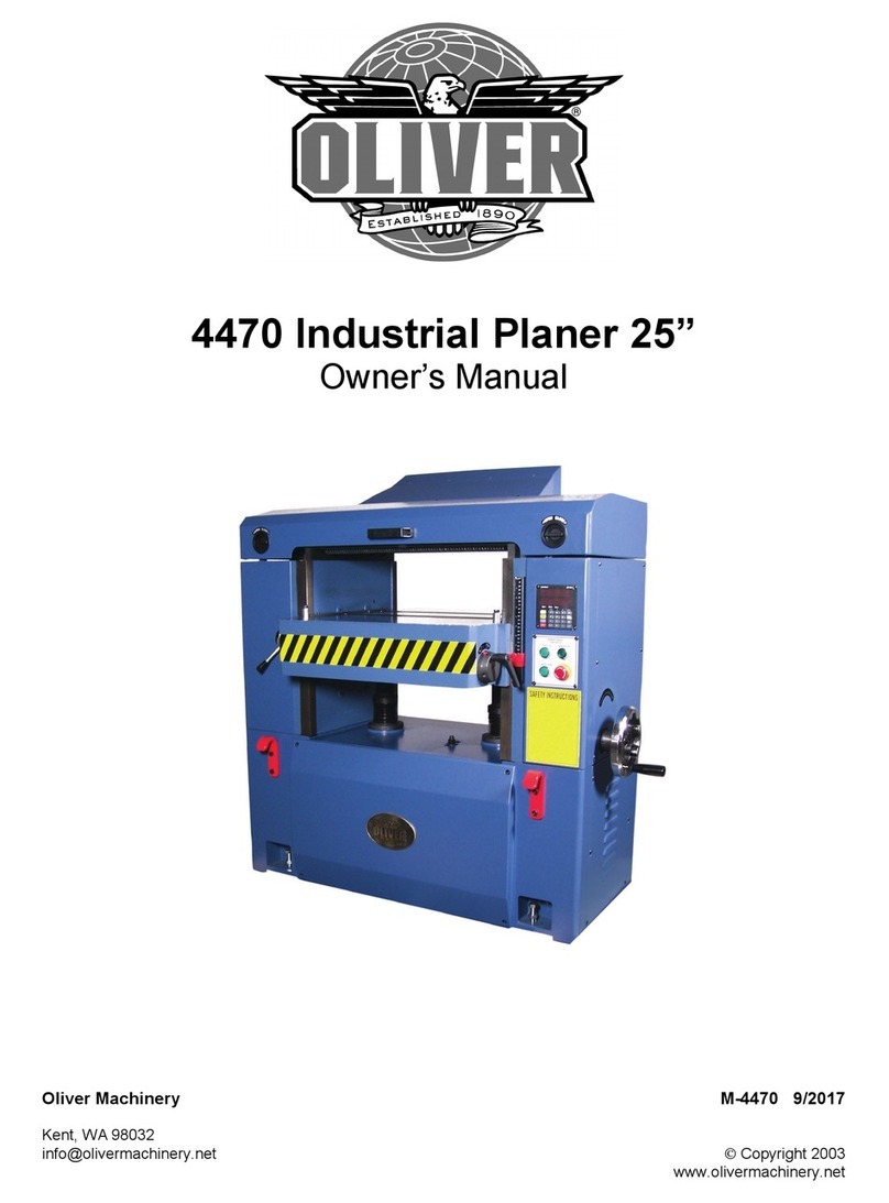
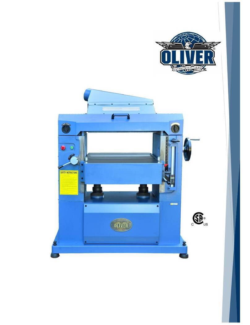
Oliver 5235 User manual

5235 24” Jointer-Planer
Owner’s Manual
Oliver Machinery M-5235 1/2018
Seattle, WA Ó Copyright 2003-2018
info@olivermachinery.net www.olivermachinery.net


2
Warranty
Oliver makes every effort possible to assure that its woodworking equipment meets the
highest possible standards of quality and durability. All products sold by Oliver are
warranted to the original customer to be free from defects for a period of 2 (two) years on
all parts, excluding electronics and motors, which are warranted for 1 year. Oliver’s
obligation under this warranty shall be exclusively limited to repairing or replacing (at
Oliver’s option) products which are determined by Oliver to be defective upon delivery
F.O.B. (return freight paid by customer) to Oliver, and on inspection by Oliver. This
warranty does not apply to defects due, directly or indirectly, to misuse, abuse,
negligence, accidents, unauthorized repairs, alterations, lack of maintenance, acts of
nature, or items that would normally be consumed or require replacement due to normal
wear. In no event shall Oliver be liable for death, personal or property injury, or damages
arising from the use of its products.
Warning
Read this manual thoroughly before operating the machine. Oliver Machinery disclaims
any liability for machines that have been altered or abused. Oliver Machinery reserves
the right to effect at any time, without prior notice, those alterations to parts, fittings, and
accessory equipment which they may deem necessary for any reason whatsoever.
For More Information
Oliver Machinery is always adding new Industrial Woodworking products to the line. For
complete, up-to-date product information, check with your local Oliver Machinery
distributor, or visit www.olivermachinery.net
3
Table of Contents
Warranty …………………………………………………………………………………..…… 2
Warning …………………………………………………………………………………..……. 2
Table of Contents …………………………………………………………………………… 3
General Safety Rules ………………………………………………………………………. 4-7
Specifications ………………………………………………………………………………….. 7
Installation ………………………………………………………………………………….... 7-9
Moving The Machine …………………………………………………………….…. 8-9
Cleaning The Machine ………………………………………………………………... 9
Machine Leveling …………………………………………………………………… 10
Power Wire Connection…………………………………………………………………….. 11
Control Panel Operation …………………………………………………………………..… 12
Control Panel Layout …………………………………………………………………….….. 12
Operating The Upper Portion Of The Machine ……………………………………….….. 13
Setting The Size ………………………………………………………………………….….. 14
Setting The Front Fence ………………………………………………………………...….. 15
Adjusting The Feed Chain ………………………………………………………………….. 16
Machine Features ………………………………………………….………………………17-18
Adjusting The Feed Rollers ………………………………………………………….…. 19-20
Adjusting The Tension ……………………………………………………..……….. 19
Adjusting The Lower Roller ………………………………………………………… 20
Adjusting The Front And Rear Pressure Plates And Keys ……………………………… 21
Changing The Lower Planing Blades ……………………………………………………… 22
Adjusting Parallelism Of Cutterhead ………………………………………………..…. 23-24
Adjusting Feed Speed ……………………………………………………….……………… 25
Digital Thickness Controller ………………………………………………………………… 26
Maintenance ……………………………………………………………………………… 27-31
Troubleshooting ……………………………………………………………………………… 32
Explosion View & Parts’ Lists…………………………………………….…………….. 33-38

4
General Safety Rules
There is a certain amount of hazard involved with the use of woodworking machinery.
Using the machine with the respect and caution demanded as far as safety precautions
are concerned will considerable lessen the possibility of personal injury. However, if
normal safety precautions are overlooked or ignored, server personal injury to the
operator can occur.
1. Read the operation manual before operating this machine.
2. If you are not thoroughly familiar with the machine operation, obtain advice from
a supervisor or other qualified person.
3. The machine should be disconnected from the power source before performing
maintenance or adjustments ot the internal mechanisms, or when making
repairs.
4. Before leaving the machine, make sure the work area is clean.
5. Check timber for loose knots, nails, or other items, which may cause a hazard or
affect the machine’s performance.
6. Learn the cutterhead’s applications and limitations, as well as the specific
potential hazards peculiar to it. Keep the cutterhead sharp for best and safest
performance.
7. Keep all guards in place and in working order.
8. Do not force the machine. it will do the job better and be safer working at the rate
for which it was designed.

5
General Safety Rules (Cont.)
9. All children and visitors should be kept a safe distance from the working area.
10. The operator should keep proper footing and balance at all times.
11. Do not operate the machine while under the influence of drugs, alcohol, or any
other medication.
12. Avoid awkward operations and hand positions where a sudden slip could cause
your hand to move into the cutterhead.
13. Never leave the machine until it comes to a complete stop, and never leave the
machine running unattended.
14. The employer is responsible for selecting competent and qualified employees.
15. The employer must make sure that employees study and utilize this safety
information.
16. Supervisors must alert personnel of any unsafe practices they observe.
17. All employees should be aware of first aid facilities and be encouraged to use
them, regardless of the severity of the injury.
18. Fire prevention must be practiced and fire protection must be available to prevent
loss of life, personal injury, and property damage.
19. Safety shoes should be worn to provide protection against rolling objects, falling
objects, and sharp edges in the workplace.

6
General Safety Rules (Cont.)
20. Eye protection should be worn and such devices should be carefully selected,
fitted and used. Compulsory wearing of glasses with impact resistant lenses and
side shields is a good safety policy. All eye protection should conform to ANSI
Z87 standards.
21. Wearing hearing protection when operating the machine.
22. Do not wear rings, necklaces or jewelry around moving machinery.
23. Do not wear loose fitting clothes. Clothing should be comfortable, but long
sleeves, neckties, etc. should not be worn.
24. Do not wear gloves or other hand covering articles around moving machinery.
25. Cover long hair with a hair net or cap
26. Protective guards and shields must be in place at all times unless they must be
removed for specific service or maintenance. They should be immediately
replaced when service or maintenance is completed.
27. Make sure that operator clearly knows how to stop the machine before starting
work.
28. Never clean or remove chips while the machine is running.
29. Maintain the machine in good operating condition. Report unusual conditions or
machine malfunctions immediately.
30. Do not alter or remove guards and warning labels.

7
General Safety Rules (Cont.)
31. Keep the immediate area clean. Do not allow the floor to become slippery or
covered with dust or obstacles. Dust that accumulates in the work area is a
hazard that can cause you to fall or slip against the machine or its controls.
32. Employees should be required to report to their supervisors any hazardous
condition of the machine or in the immediate area.
Specifications
MODEL
5230
5235
Max. Working Width
18” (457mm)
24” (610mm)
Max. Working Thickness
4 51/64” (120mm)
8” (200mm)
Max. Working Length
12” (300mm)
12” (300mm)
Composition Of Knives
Solid Carbide
Solid Carbide
Knife Style
30mm x 12mm x 1.5T
30mm x 12mm x 1.5T
Cutterhead Speed
4600 RPM
4600RPM
Feeding Speed
20’ – 60’/min
20’ – 95’/min
Upper Cutterhead Motor
20HP
25HP
Bottom Cutterhead Motor
15HP
25HP
Feed Drive Motor
2, 3HP
7.5HP
Elevation Drive Motor
1HP
1HP
Machine Dimensions
L2520xW1400xH1600mm
L2730xW1700xH1700mm
Packing Dimensions
L2650xW1550xH1800mm
L2950xW1850xH1830mm
N.W. / G.W.
6,614/7,385 lbs
8,818/9,700 lbs
CFM Dust Requirement
3500 CFM
4200 CFM

8
INSTALLATION
Moving the Machine
The machine is usually packed in a wooden crate.
The packing dimensions are
5230 – L2650 x W1550 x H1800 mm
5235 – L2950 x W1850 x H1830 mm
While in the packing crate, the machine should be lifted and moved by a forklift.
Attention should be paid to the balance of the machine while lifting and transporting.
Use a forklift with sufficient capacity to move the machine.

9
Moving the Machine (Cont.)
Once the machine has been unpacked from the crate, move it to the work site using a
hoist and straps. The following guidelines should be followed when transporting the
machine by this method.
(1) The straps should have a capacity of at least 3 times the weight of the machine.
Refer to the specifications for the weight of each model.
(2) Inspect the straps for fray and cuts before using.
(3) Secure all movable parts of the machine and remove movable accessories
before moving.
(4) The transportation should be done only by trained and qualified personnel.
(5) Keep all other people away from the path of the machine.
Cleaning the Machine
The machine is coated with rust preventative oil before shipment. When the machine
has been moved to a proper work site, wipe the oil from the machine. Use a soft cloth
soaked in kerosene to clean the rust preventative oil from the machine. do not use
gasoline, lacquer thinner, or any other volatile solvent, as these may damage the
painted surface of the machine.

10
Machine Leveling
The machine should be installed in an area largo enough to allow personnel to move
freely around the machine during operation and maintenance, and to allow the safe
feeding and removal of workpieces from the machine. The ground should be flat and
rigid enough to support the machine. it is not necessary to bolt the machine to the
ground. Place steel plates under the leveling bolts and use two precision level gauges
on the infeed table to level the machine. level the machine with 8 leveling bolts (A) and
(B) shown in figure below.

11
Power Wire Connection
A cable with 4 wires is supplied for connection to the power supply. The power supply
can be of 380, 400 or 415V. When connecting the power supply, always connect the
grounding to the free/yellow wire first. When disconnecting the power always disconnect
the ground last.
On the door of the control cabinet, there is a hand-operated power disconnection
device. Before connecting or disconnecting power, or performing any maintenance or
inspection work, always switch this device to the “OFF” position and lock it to prevent
accidental starting.
After the power has been connected, switch the power device to the “ON” position, and
run the main motor. Make sure the rotation direction is correct. If the rotation is
incorrect, switch off and disconnect the power supply, and change the phase lines to a
correct connection.
The electrical system should be fuse protected as indicated below.
(Dependent the horse power)
Model
Current Rating
Fuse Capacity
5235
77HP
120A
150 KArms

12
Control Panel Operation
After the planning thickness has been properly set, turn on the power and turn off the
brake with the corresponding switches. Press the buttons to start the planning knife
spindles and feed conveyor running. The machine is then ready to start planning.
The feed conveyor can only be started when the lower and upper spindles are running.
If the upper or lower spindles stop running, the feed conveyor will also stop and cannot
be started again until both spindles are running.
Refer to control panel diagram for layout and function of switches.
Optional: Hour Meter. Speed Meter.
Control Panel Layout

13
Operating the Upper Portion of the Machine
Elevation buttons for the upper portion of the machine are located at the lower front side
of the machine. A hand wheel is located below the elevation buttons for fine adjustment
of the working thickness of the workpiece. A hand wheel located under the fence is for
making adjustment of the infeed table.
See figure below for part identification.

14
Setting the Size
The amount to be planed from the bottom of the workpiece is set by adjusting the height
of the infeed table in relation to the bottom cutterhead This is done by using the infeed
table adjustment hand wheel, located under the infeed table. The gauge for reading the
planning amount is located to the right of the pointer gauge, on the infeed table.
Once the lower planning value is set, use the elevation buttons and micrometric
adjustment hand wheel to move the upper portion of the machine, so that the upper
planning amount is set. The total amount to be planed will be read on the thickness
gauge. Make a trial cut and measure the planed workpiece to confirm that the thickness
gauge is correctly calibrated.
NOTE:
It it recommended that a cutting ration of 1.5:1 be used for upper and lower
cutting. i.e., to plane 10mm from the workpiece, set the lower planning value to
4mm and the upper planning value to 6mm.
The maximum lower planning value is 5mm, and the maximum upper planning
value is 8mm.

15
Setting the Front Fence
If the planning thickness is too great, then the machine may become clogged and
damaged. There is a fence at the infeed side to prevent workpieces from being fed in
such a way that too much material would be removed at one time. The upper portion of
the machine should be set so that there is at least 6mm clearance between the fence
and the workpiece.

16
Adjusting the Feed Chain
The feed chain tension is adjusted by the two chain tension screws located at either
side of the infeed end of the table. If the feed chain is too loose, it will cause binding and
excess noise during workpiece feed. Tighten the screws to increase tightness.
To adjust the pressure, loosen the fixing lever on the eccentric board, and move the
eccentric board up or down to obtain the correct pressure. Retighten the fixing lever
after adjustment, in general, greater feed chain pressured is required for harder woods.
Check the relative hardness of the wood stock before planning.

17
Machine Features
1. Belt tension adjustment
2. Upper cutterhead motor
3. Feed motor
4. Control panel
5. Elevation buttons for upper portion of machinery
6. Electrical cabinet
7. Infeed table
8. Infeed table elevation hand wheel
9. Spike conveyor (feed chain)
10. Lower cutterhead thickness gauge
11. Thickness gauge
12. Micrometric elevation adjustment hand wheel
13. Elevation motor for upper portion of machinery
14. Elevation tube screw and nut
15. Lower knife replacing tray
16. Elevation limit power off rod
17. Column
18. Outfeed table

18
15
9
16
14
13
12
10
11
8
7
6
5
4
1
2
3
17
18

19
Adjusting the Feed Rollers
There is one section and one steel fine roller on the upper portion of the feed bed, and
three steel rollers on the bottom the top rollers are pressure rollers and keep the
workpiece from jumping during feed.
To adjust the tension of the rollers, adjust the pressure screws and nuts located at
either side of each roller. If there is insufficient pressure, the lumber will slip. Too much
may cause damage to the workpiece.
This manual suits for next models
1
Table of contents
Other Oliver Planer manuals

Oliver
Oliver 4420 User manual

Oliver
Oliver 5240 User manual

Oliver
Oliver 4420 User manual

Oliver
Oliver 0015 User manual

Oliver
Oliver 4430 User manual

Oliver
Oliver 4430.201 M-4430 User manual

Oliver
Oliver 4455 User manual

Oliver
Oliver 4455 User manual

Oliver
Oliver 4470 User manual

Oliver
Oliver 10014 User manual
Popular Planer manuals by other brands

Powermatic
Powermatic WP2412 Operating instructions and parts manual

Lindahl & Nermark
Lindahl & Nermark LPT 310 X manual

VITO
VITO PRO-POWER VIPL850 instruction manual

Trelawny SPT
Trelawny SPT TFP320 operation & maintenance

H. Winter
H. Winter DUOMAX GT-400BRD-CE Operation manual

Hitachi Koki
Hitachi Koki P 20ST Handling instructions