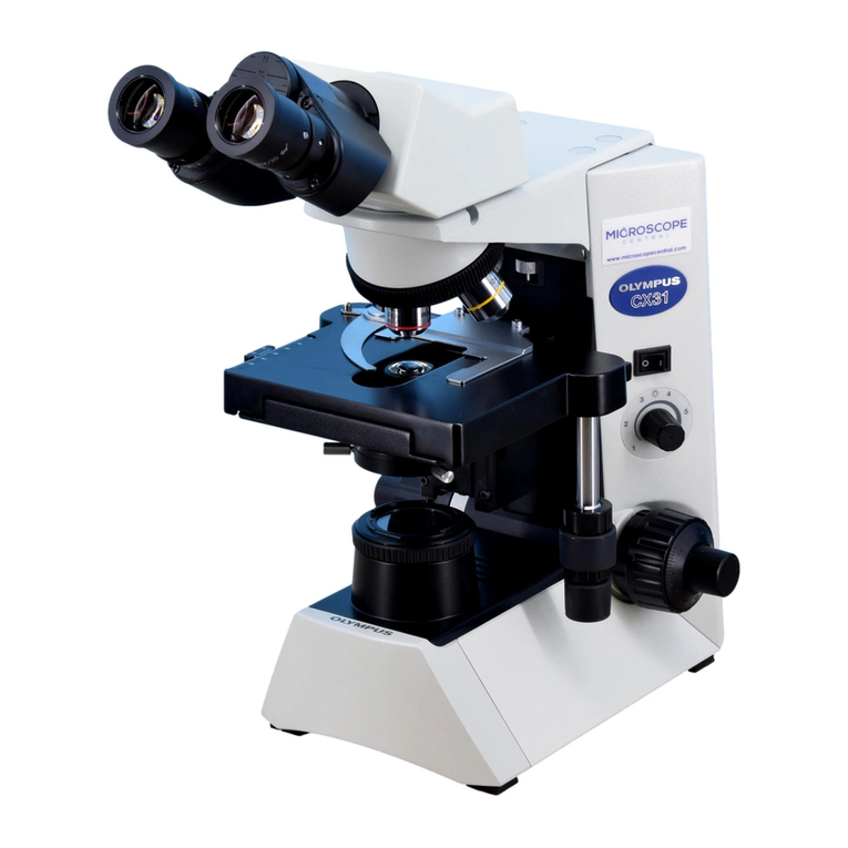
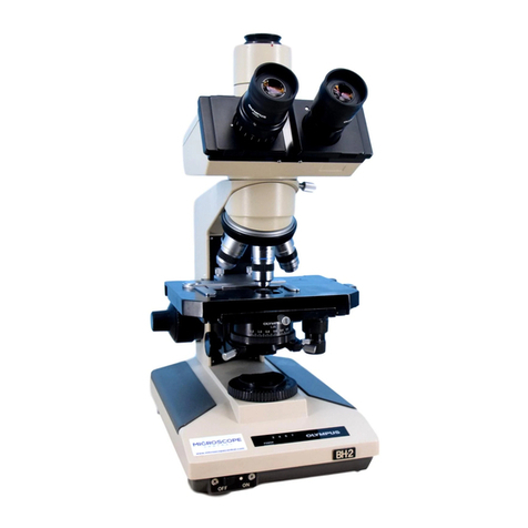
Olympus BH2-CH Substage User manual

Complete Teardown, Cleaning/Lubrication, and Reassembly of the Olympus BH2-CH Substage Assembly Revision 1 Page 1 of 26
Complete Teardown, Cleaning/Lubrication,
and Reassembly of the Olympus
BH2-CH Substage Assembly
Revision 1
Copyright © 2017 Carl Hunsinger
All rights reserved. This document may not be reproduced or distributed, in whole or in part, for any
commercial purpose without the express written consent of the author ([email protected]). Permission is
hereby granted to distribute this PDF document in its entirety for personal, non-commercial purposes only,
provided that the contents are not modified in any way, including the copyright notices contained herein. This
document may be freely distributed on WWW, FTP, or BBS sites in accordance with these restrictions.
The content of this document is provided for informational purposes only, with no expressed or implied
warranties whatsoever, including, but not limited to, function, suitability, safety, accuracy, or completeness of
information.
Revision History
Revision
Description of Changes
Date
1
Initial Release
August 13, 2017

Complete Teardown, Cleaning/Lubrication, and Reassembly of the Olympus BH2-CH Substage Assembly Revision 1 Page 2 of 26
Table of Contents
Introduction _____________________________________________________________________________ 6
Scope of this Document ____________________________________________________________________ 6
Tools Needed ____________________________________________________________________________ 6
A Few Words about JIS Screws _____________________________________________________________________ 6
Supplies Needed __________________________________________________________________________ 6
Recommended Lubricants _________________________________________________________________________ 6
Recommended Solvents __________________________________________________________________________ 6
Safety Considerations with Solvents _________________________________________________________________ 6
Solvent Compatibility with Parts and Finishes__________________________________________________________ 6
Common Problems with the BH2-CH Substage __________________________________________________ 7
Inability to Center the Condenser ___________________________________________________________________ 7
Stiffness in the Condenser-Slide Mechanism___________________________________________________________ 7
Erratic Condenser-Height Adjustment________________________________________________________________ 7
Teardown/Reassembly of BH2-CH Substage ____________________________________________________ 7
Remove the Condenser-Slide Assembly ______________________________________________________________ 7
Remove the Locking and Centering Thumbscrews ______________________________________________________ 8
Remove the Slip Plates____________________________________________________________________________ 8
Remove the Centering Yoke from the Support Yoke_____________________________________________________ 9
Remove the Condenser-Height Rack _________________________________________________________________ 9
Disassemble the Condenser-Height Stop_____________________________________________________________ 10
Reassemble the Condenser-Height Stop _____________________________________________________________ 11
Disassemble the Centering Plunger _________________________________________________________________ 12
Reassemble the Centering Plunger _________________________________________________________________ 13
Reinstall the Condenser-Height Rack________________________________________________________________ 14
Reinstall the Centering Yoke into the Support Yoke ____________________________________________________ 14
Reinstall the Slip Plates __________________________________________________________________________ 15
Reinstall the Locking and Centering Thumbscrews _____________________________________________________ 16
Disassemble the Friction Lock _____________________________________________________________________ 16
Reassemble the Friction Lock______________________________________________________________________ 16
Remove the Dovetail Blocks ______________________________________________________________________ 17
Remove the Condenser-Height Knob _______________________________________________________________ 18
Remove the Condenser-Height Shaft _______________________________________________________________ 18
Reinstall the Condenser-Height Shaft _______________________________________________________________ 20
Reinstall the Condenser-Height Knob _______________________________________________________________ 22
Adjust the Tension of the Condenser-Height Shaft _____________________________________________________ 23
Reinstall the Dovetail Blocks ______________________________________________________________________ 23
Reinstall the Condenser-Slide Assembly _____________________________________________________________ 24
Adjust the Condenser-Height Stop ___________________________________________________________ 25
Ready for Service ________________________________________________________________________ 25
Original Olympus Documentation ___________________________________________________________ 25
How to Contact the Author_________________________________________________________________ 25
Appendix 1 _____________________________________________________________________________ 26
Parts, Supplies, and Tools ________________________________________________________________________ 26
Sources for Parts, Supplies, and Tools _______________________________________________________________ 26

Complete Teardown, Cleaning/Lubrication, and Reassembly of the Olympus BH2-CH Substage Assembly Revision 1 Page 3 of 26
Table of Figures
Figure 1 –Head of a typical JIS screw ..................................................................................................................................... 6
Figure 2 –Adjust condenser height until screw is visible ....................................................................................................... 7
Figure 3 –Unscrew and remove the slotted stop screw ........................................................................................................ 7
Figure 4 –Remove the condenser slide assembly.................................................................................................................. 8
Figure 5 –Remove the condenser-lock thumbscrew ............................................................................................................. 8
Figure 6 –Remove the centering thumbscrews ..................................................................................................................... 8
Figure 7 –The condenser-slide assembly (bottom view) ....................................................................................................... 8
Figure 8 –Remove screws securing the slip plates................................................................................................................. 8
Figure 9 –Remove the three slip plates ................................................................................................................................. 8
Figure 10 –Look for shim washers under the slip plates........................................................................................................ 9
Figure 11 –Remove any brass shim washers ......................................................................................................................... 9
Figure 12 –Depress the centering plunger............................................................................................................................. 9
Figure 13 –Separate centering yoke from support yoke ....................................................................................................... 9
Figure 14 –The support yoke on the condenser slide............................................................................................................ 9
Figure 15 –The centering yoke............................................................................................................................................... 9
Figure 16 –Remove screws and washers securing rack ....................................................................................................... 10
Figure 17 –Remove the condenser-height rack ................................................................................................................... 10
Figure 18 –Brass shim for the condenser-height rack ......................................................................................................... 10
Figure 19 –Remove brass shim for condenser-height rack.................................................................................................. 10
Figure 20 –Loosen set screw while holding the stop pin ..................................................................................................... 10
Figure 21 –Remove the loose stop pin from the bore......................................................................................................... 10
Figure 22 –Remove the stop-pin spring from the slide ....................................................................................................... 11
Figure 23 –Back out the stop-pin set screw from the slide ................................................................................................. 11
Figure 24 –Test the fit of the stop pin in the bore............................................................................................................... 11
Figure 25 –Clean any debris or burring from the bore ........................................................................................................ 11
Figure 26 –Reinstall the stop-pin spring into the bore ........................................................................................................ 11
Figure 27 –Reinstall the stop pin into the bore ................................................................................................................... 11
Figure 28 –Tighten set screw to lock the stop pin ............................................................................................................... 12
Figure 29 –Test centering plunger for freedom of motion.................................................................................................. 12
Figure 30 –Loosen the plunger-retaining screw .................................................................................................................. 12
Figure 31 –Remove the plunger-retaining screw................................................................................................................. 12
Figure 32 –Remove the plunger-extension spring............................................................................................................... 12
Figure 33 –Press centering plunger out the back of bore.................................................................................................... 12
Figure 34 –Remove centering plunger from the bore ......................................................................................................... 13
Figure 35 –Clean grease from bore and dovetail slide ........................................................................................................ 13
Figure 36 –Apply grease to the centering-plunger bore...................................................................................................... 13
Figure 37 –Reinstall plunger and c-clip into bore ................................................................................................................ 13
Figure 38 –Reinstall plunger-extension spring into bore..................................................................................................... 13
Figure 39 –Reinstall the plunger-retaining screw ................................................................................................................ 13
Figure 40 –Tighten the plunger-retaining screw.................................................................................................................. 14
Figure 41 –Head of retaining screw must be recessed........................................................................................................ 14
Figure 42 –Reinstall brass shim for condenser-height rack ................................................................................................. 14
Figure 43 –Reinstall screws for the condenser-height rack................................................................................................. 14
Figure 44 –Tighten screws for the condenser-height rack................................................................................................... 14
Figure 45 –Parts for the condenser-centering mechanism.................................................................................................. 14
Figure 46 –Lightly grease the underside of centering yoke................................................................................................. 15
Figure 47 –Reinstall centering yoke into support yoke ....................................................................................................... 15
Figure 48 –Reinstall any brass shim washers....................................................................................................................... 15
Figure 49 –Apply grease to the three slip bosses ................................................................................................................ 15
Figure 50 –Reinstall slip plates onto the slip bosses............................................................................................................ 15
Figure 51 –Reinstall screws to secure the slip plates........................................................................................................... 15

Complete Teardown, Cleaning/Lubrication, and Reassembly of the Olympus BH2-CH Substage Assembly Revision 1 Page 4 of 26
Figure 52 –Lightly grease the locking thumbscrew.............................................................................................................. 16
Figure 53 –Reinstall the locking thumbscrew ...................................................................................................................... 16
Figure 54 –Lightly grease the centering thumbscrews ........................................................................................................ 16
Figure 55 –Reinstall the centering thumbscrews................................................................................................................. 16
Figure 56 –Loosen and remove the friction-lock screw....................................................................................................... 16
Figure 57 –Remove the plastic friction lock from housing .................................................................................................. 16
Figure 58 –Reinstall the plastic friction lock in bore............................................................................................................ 17
Figure 59 –Reinstall the friction-lock screw......................................................................................................................... 17
Figure 60 –Remove screws from right dovetail block.......................................................................................................... 17
Figure 61 –Remove right dovetail block from the housing.................................................................................................. 17
Figure 62 –Dovetail blocks with alignment pins .................................................................................................................. 17
Figure 63 –Remove screws from left dovetail block............................................................................................................ 17
Figure 64 –Remove left dovetail block from the housing.................................................................................................... 18
Figure 65 –Clean grease from the dovetail blocks............................................................................................................... 18
Figure 66 –Loosen set screws in condenser-height knob .................................................................................................... 18
Figure 67 –Remove the condenser-height knob.................................................................................................................. 18
Figure 68 –Loosen the tension-screw lock nut .................................................................................................................... 18
Figure 69 –Unscrew and remove tension-screw lock nut.................................................................................................... 18
Figure 70 –Loosen the tension screw in housing................................................................................................................. 19
Figure 71 –Unscrew and remove the tension screw............................................................................................................ 19
Figure 72 –Bearing ball on the end of the tension screw .................................................................................................... 19
Figure 73 –Bearing ball on the end of the pinion gear ........................................................................................................ 19
Figure 74 –Press or tap pinion shaft into main housing ...................................................................................................... 19
Figure 75 –Press shaft until pinion gear protrudes.............................................................................................................. 19
Figure 76 –Remove the bearing ball from the pinion gear.................................................................................................. 20
Figure 77 –Withdraw the pinion shaft from main housing.................................................................................................. 20
Figure 78 –Remove metal washer from the pinion shaft .................................................................................................... 20
Figure 79 –Remove nylon washer from the main housing .................................................................................................. 20
Figure 80 –Components of the condenser-height shaft ...................................................................................................... 20
Figure 81 –Clean grease from bore in the main housing..................................................................................................... 20
Figure 82 –Place washer in recess in the main housing....................................................................................................... 21
Figure 83 –Grease the left-hand bore in main housing ....................................................................................................... 21
Figure 84 –Place metal washer over greased pinion shaft .................................................................................................. 21
Figure 85 –Insert pinion shaft into the right-hand bore ...................................................................................................... 21
Figure 86 –Seat pinion gear onto main housing ledge......................................................................................................... 21
Figure 87 –Apply grease to the end of the tension screw ................................................................................................... 21
Figure 88 –Place ball into greased end of tension screw..................................................................................................... 22
Figure 89 –Insert tension screw into right-hand bore ......................................................................................................... 22
Figure 90 –Engage threads of tension screw with housing ................................................................................................. 22
Figure 91 –Slightly tighten the tension screw to hold ball................................................................................................... 22
Figure 92 –Reinstall the tension-screw lock nut.................................................................................................................. 22
Figure 93 –Reinstall knob onto condenser-height shaft...................................................................................................... 22
Figure 94 –Tighten set screws to secure the height knob ................................................................................................... 23
Figure 95 –Adjust tension screw for no thrust play............................................................................................................. 23
Figure 96 –Tighten lock nut to secure tension screw .......................................................................................................... 23
Figure 97 –Place right-hand dovetail block onto housing.................................................................................................... 23
Figure 98 –Reinstall screws to secure right dovetail block .................................................................................................. 23
Figure 99 –Place left-hand dovetail block onto housing...................................................................................................... 23
Figure 100 –Reinstall screws to secure left dovetail block .................................................................................................. 24
Figure 101 –Grease the bearing surfaces for the slide ........................................................................................................ 24
Figure 102 –Grease flat bearing surfaces of dovetail slide .................................................................................................. 24
Figure 103 –Grease beveled surfaces of dovetail slide........................................................................................................ 24
Figure 104 –Engage condenser slide with dovetail blocks................................................................................................... 24

Complete Teardown, Cleaning/Lubrication, and Reassembly of the Olympus BH2-CH Substage Assembly Revision 1 Page 5 of 26
Figure 105 –Align the hole in slide with the tapped hole .................................................................................................... 24
Figure 106 –Reinstall the condenser-slide stop screw......................................................................................................... 25
Figure 107 –The condenser set to maximum height ........................................................................................................... 25
Figure 108 –The set screw for the condenser-height stop .................................................................................................. 25
Figure 109 –Olympus BH2 (BHS) repair manual .................................................................................................................. 25

Complete Teardown, Cleaning/Lubrication, and Reassembly of the Olympus BH2-CH Substage Assembly Revision 1 Page 6 of 26
Introduction
The microscopes in the Olympus BH-2 line (BHS, BHSU,
BHT, and BHTU) have largely been replaced in the
professional and clinical world, due to their advancing
age and the lack of repair parts from Olympus. A great
many of these microscopes were produced in their day,
and because of this are they readily available on the
used market for very reasonable prices. Thanks to their
excellent build quality and solid optical performance,
these scopes are now very popular with hobbyists,
providing an affordable, high-quality alternative to the
Chinese-made scopes prevalent today.
The BH2-CH substage assembly (sometimes referred to
as the Condenser Holder) on the BH-2 equipment
mounts onto the sliding focus block of the stand, and
provides a ring for the mechanical stage to mount onto,
as well as a centering mount for the substage
condenser. The height of the substage condenser can
be adjusted, relative to the stage, by a rack-and-pinion
mechanism, and the maximum condenser height can be
precisely set by the adjustable condenser-height stop.
Due to the age of BH-2 equipment, the BH2-CH
substage assembly frequently needs disassembled and
regreased to function well again.
Scope of this Document
This document describes the complete teardown,
cleaning/lubrication, and reassembly of the BH2-CH
substage assembly used on the Olympus BH-2 series of
microscopes.
Tools Needed
The following tools are needed to service the BH2-CH
substage assembly:
Allen wrench or driver, 1.5mm (item 4 of Appendix 1)
Allen wrench or driver, 2.5mm (item 5 of Appendix 1)
Allen wrench or driver, 3.0mm (item 6 of Appendix 1)
Center punch (or nailset)
Pliers, needle-nose (fine-point)
Screwdriver set, JIS (item 7 of Appendix 1)
Screwdriver set, slotted
A Few Words about JIS Screws
Screws with JIS heads are found in much of the
equipment designed and manufactured in Japan. JIS
screws look very much like standard Phillips screws, but
they differ in that JIS screws were designed to not cam-
out under torque, whereas Phillips screws were
designed to intentionally cam-out, as a means to limit
the torque applied to the fasteners. Because of this
crucial difference in the geometry of the two screw
types, JIS screws will be damaged by standard Phillips
drivers if too much torque is applied. JIS screws can
usually be identified by the presence of a single dot, or
by an “X”, stamped into one of the four quadrants of
the cross-point depression (see Figure 1).
Figure 1 –Head of a typical JIS screw
Supplies Needed
The following supplies are needed to service the
BH2-CH substage assembly:
Cleaning solvent (see Recommended Solvents section below)
Cotton swabs
Grease (see Recommended Lubricants section below)
Tissues, oil-free
Recommended Lubricants
Dow Molykote® 44 (item 2 of Appendix 1) or Nye 704C
(item 3 of Appendix 1) is recommended for the BH2-CH
substage assembly. Both of these greases are
sufficiently light for the greased dovetail slides, and
both types will remain stable and serviceable for many
years to come.
Recommended Solvents
Some type of cleaning solvent will be needed to remove
the old grease from the various components of the
BH2-CH substage assembly. Solvents that can be used
are acetone, diethyl ether, heptane, hexane, mineral
spirits, turpentine, and xylene.
Safety Considerations with Solvents
Regardless of which solvent is chosen, make sure that
adequate ventilation is present during the cleaning
process, and that any necessary personal protective
equipment is utilized to minimize exposure. Consult the
MSDS sheet before using any unfamiliar solvents. Many
of the solvents listed above are flammable, and their
vapors may represent an explosion hazard if
mishandled. Whichever solvents are chosen, be sure to
follow all manufacturer’s instructions and safety
precautions.
Solvent Compatibility with Parts and Finishes
Many solvents will damage the finish of painted
surfaces (isopropyl alcohol or 409 Cleaner may be safely

Complete Teardown, Cleaning/Lubrication, and Reassembly of the Olympus BH2-CH Substage Assembly Revision 1 Page 7 of 26
used to clean most painted surfaces). Additionally,
many solvents will dissolve or damage plastic parts. Do
not allow untested solvents to contact the plastic
condenser-height knob or the plastic gear rack, as these
parts may be damaged by exposure to solvents. Before
using any solvent to clean plastic parts, test a small
amount of the solvent in an inconspicuous area of the
part (such as inside the knob) to ensure compatibility
with the plastic. Never use xylene to clean nylon parts,
as xylene dissolves nylon. Isopropyl alcohol and
trichloroethylene will cause swelling of nylon due to
solvent absorption. The list of solvents generally
considered safe for nylon includes acetone, diethyl
ether, heptane, mineral spirits, naphthalene, and
turpentine.
Common Problems with the BH2-CH Substage
A few of the more common problems which can affect
the BH2-CH substage assembly are discussed below.
Inability to Center the Condenser
Stiffness in the centering plunger or in the centering
yoke in the condenser-centering mechanism can cause
impaired condenser centering of the BH2-CH. This is
usually caused by dried, stiff grease in the centering
mechanism, and can be corrected by performing the
teardown, cleaning/lubrication, and reassembly
procedure described in the relevant sections below.
Stiffness in the Condenser-Slide Mechanism
Stiffness in the condenser-slide mechanism can cause
damage to the plastic condenser-height rack if the
problem gets bad enough. This is usually caused by
dried, stiff grease in the condenser-slide mechanism,
and can be corrected by performing the teardown,
cleaning/lubrication, and reassembly procedure
described in the relevant sections below.
Erratic Condenser-Height Adjustment
Erratic operation, no operation, or binding of the
condenser-height mechanism can be caused by dirt or
debris in the teeth of the pinion gear or in the teeth of
the plastic condenser-height rack, or by damage to the
teeth of the condenser-height rack. If the problem is
caused by dirt or debris in the teeth of the rack or
pinion gear, this can be corrected by performing the
teardown, cleaning/lubrication, and reassembly
procedure described in the relevant sections below. If
the problem is caused by damage to the condenser-
height rack, this can be corrected by replacing the rack
1
,
but the rack should only be replaced as part of the full
teardown, cleaning/lubrication, and reassembly
1
Parts for the BH2-CH, including the condenser-height rack, are no longer
available from Olympus.
procedure described below, since damage to the new
rack can be caused by dry, thickened grease in the
condenser-slide mechanism.
Teardown/Reassembly of BH2-CH Substage
The procedure for disassembling, cleaning/lubricating,
and reassembling the BH2-CH substage assembly is
described in the sections below. During the teardown
of the BH2-CH substage assembly, be sure to bag and
tag the various components, to prevent their loss and to
facilitate their proper identification during later
reassembly.
Remove the Condenser-Slide Assembly
The first step in the disassembly procedure is to remove
the condenser-slide assembly from the main housing of
the substage. To do this, use the condenser-height
knob to adjust the position of the condenser slide until
the hole in the condenser slide aligns with the slotted
stop screw (see Figure 2).
Figure 2 –Adjust condenser height until screw is visible
Next, use a suitable slotted screwdriver to remove the
M2.6x4 slotted stop screw (see Figure 3).
Figure 3 –Unscrew and remove the slotted stop screw
Rotate the condenser-height knob clockwise until the
condenser-slide assembly disengages from the bottom
of the main housing (see Figure 4).

Complete Teardown, Cleaning/Lubrication, and Reassembly of the Olympus BH2-CH Substage Assembly Revision 1 Page 8 of 26
Figure 4 –Remove the condenser slide assembly
Remove the Locking and Centering Thumbscrews
Loosen and remove the condenser-lock thumbscrew
from the centering yoke (see Figure 5).
Figure 5 –Remove the condenser-lock thumbscrew
Loosen and remove the two centering thumbscrews
from the support yoke (see Figure 6).
Figure 6 –Remove the centering thumbscrews
Remove the Slip Plates
The condenser-slide assembly is shown in Figure 7.
Figure 7 –The condenser-slide assembly (bottom view)
Use a suitable JIS screwdriver to remove the six M2x4
JIS screws securing the three slip plates to the centering
yoke (see Figure 8).
Figure 8 –Remove screws securing the slip plates
Remove the three loose slip plates (see Figure 9), being
careful to not lose any small brass shim washers that
may be beneath the slip plates.
Figure 9 –Remove the three slip plates

Complete Teardown, Cleaning/Lubrication, and Reassembly of the Olympus BH2-CH Substage Assembly Revision 1 Page 9 of 26
Note the location of any small, brass shim washers that
may be present beneath any of the slip plates so that
they can be returned to their proper place during
reassembly (see Figure 10).
Figure 10 –Look for shim washers under the slip plates
Carefully remove any brass shim washers that are
present beneath the slip plates (see Figure 11).
Figure 11 –Remove any brass shim washers
Remove the Centering Yoke from the Support Yoke
Place your thumb in position on the centering yoke as
shown in Figure 12, and press in on the centering yoke
to depress the centering plunger.
Figure 12 –Depress the centering plunger
While holding the centering yoke such that the
centering plunger is depressed, separate the centering
yoke from the support yoke (see Figure 13).
Figure 13 –Separate centering yoke from support yoke
The various components of the support yoke (which is
part of the condenser slide) are shown in Figure 14.
Figure 14 –The support yoke on the condenser slide
The centering yoke is shown in Figure 15.
Figure 15 –The centering yoke
Remove the Condenser-Height Rack
Use a suitable JIS screwdriver to remove the two
M2.6x6 JIS screws and washers securing the condenser-
height rack to the dovetail slide (see Figure 16).

Complete Teardown, Cleaning/Lubrication, and Reassembly of the Olympus BH2-CH Substage Assembly Revision 1 Page 10 of 26
Figure 16 –Remove screws and washers securing rack
Remove the loose condenser-height rack from the face
of the dovetail slide (see Figure 17).
Figure 17 –Remove the condenser-height rack
Look for a brass shim either on the back of the
condenser-height rack or on the face of the dovetail
slide (see Figure 18).
Figure 18 –Brass shim for the condenser-height rack
Remove the brass shim from the back of the condenser-
height rack or from the face of the dovetail slide,
whichever is applicable (see Figure 19).
Figure 19 –Remove brass shim for condenser-height rack
Disassemble the Condenser-Height Stop
Hold the M5x12 condenser-height stop pin down with
your finger, and use a 1.5mm Allen wrench or driver to
loosen the M3x4 set screw holding the stop pin in place.
While holding your finger on top of the stop pin, allow
the stop pin to rise in order to alleviate the compression
on the internal stop spring (see Figure 20).
Figure 20 –Loosen set screw while holding the stop pin
Remove the M5x12 stop pin from the bore in the
condenser slide (see Figure 21).
Figure 21 –Remove the loose stop pin from the bore
Remove the stop-pin spring from the bore in the
condenser slide (see Figure 22).

Complete Teardown, Cleaning/Lubrication, and Reassembly of the Olympus BH2-CH Substage Assembly Revision 1 Page 11 of 26
Figure 22 –Remove the stop-pin spring from the slide
Reassemble the Condenser-Height Stop
Use a 1.5mm Allen wrench or driver to back out the
M3x4 stop-pin set screw so that the threads do not
protrude into the bore in the condenser slide (see
Figure 23).
Figure 23 –Back out the stop-pin set screw from the slide
Use a cotton swab and a suitable solvent (e.g., acetone)
to thoroughly clean the stop pin and the bore of the
condenser slide. Test the fit of the stop pin in the bore.
The pin should slide freely in the bore without any
noticeable friction or binding (see Figure 24).
Figure 24 –Test the fit of the stop pin in the bore
It is critical to the operation of the condenser-height
stop that this pin move freely in the bore in the
condenser slide. If there is noticeable friction or any
binding present, use a .1990” (i.e., 5.05mm) twist drill
bit to clean the bore of any debris or internal burring
(see Figure 25).
Figure 25 –Clean any debris or burring from the bore
Place the stop-pin spring into the bore in the condenser
slide (see Figure 26).
Figure 26 –Reinstall the stop-pin spring into the bore
Place the M5x12 stop pin into the bore in the condenser
slide (see Figure 27).
Figure 27 –Reinstall the stop pin into the bore
Use a 1.5mm Allen wrench or driver to tighten the
M3x4 set screw to secure the stop pin in position (see
Figure 28).

Complete Teardown, Cleaning/Lubrication, and Reassembly of the Olympus BH2-CH Substage Assembly Revision 1 Page 12 of 26
Figure 28 –Tighten set screw to lock the stop pin
Disassemble the Centering Plunger
Test the operation of the spring-loaded centering
plunger by pressing the plunger in, and then observing
how freely the plunger extends when the pressure is
released (see Figure 29). If the plunger quickly returns
to the fully extended position when the pressure is
released, skip ahead to the Reinstall the Condenser-
Height Rack section of this document. Otherwise,
proceed with the teardown of the centering plunger as
described below.
Figure 29 –Test centering plunger for freedom of motion
Use a suitable slotted screwdriver to loosen (but do not
remove) the plunger-retaining screw (see Figure 30).
Figure 30 –Loosen the plunger-retaining screw
Unscrew and remove the plunger-retaining screw, being
careful that the compressed spring behind the screw
does not fly out and become lost (see Figure 31).
Figure 31 –Remove the plunger-retaining screw
Remove the plunger-extension spring, which is located
in the bore behind the plunger-retaining screw (see
Figure 32).
Figure 32 –Remove the plunger-extension spring
Use a suitable blunt tool to press the centering plunger
into the bore in the front of the condenser slide and out
the opposite side (i.e., out the bore on the face of the
dovetail slide). Grasp the plunger and attached c-clip
protruding from the face of the dovetail slide and
withdraw the plunger and c-clip from the bore (see
Figure 33 and Figure 34).
Figure 33 –Press centering plunger out the back of bore

Complete Teardown, Cleaning/Lubrication, and Reassembly of the Olympus BH2-CH Substage Assembly Revision 1 Page 13 of 26
Figure 34 –Remove centering plunger from the bore
Reassemble the Centering Plunger
Use a cotton swab wetted with a suitable solvent (e.g.,
acetone) to clean any old grease from the plunger and
spring. Also clean the bore in the condenser slide, the
face of the dovetail slide, and the bearing surfaces on
the face and bevels of the dovetail slide (see Figure 35).
Figure 35 –Clean grease from bore and dovetail slide
Apply fresh grease to the centering-plunger bore in the
condenser slide (see Figure 36).
Figure 36 –Apply grease to the centering-plunger bore
Insert the centering plunger, with attached c-clip, into
the centering-plunger bore in the face of the dovetail
slide (see Figure 37).
Figure 37 –Reinstall plunger and c-clip into bore
Insert the plunger-extension spring into the centering-
plunger bore in the face of the dovetail slide (see Figure
38).
Figure 38 –Reinstall plunger-extension spring into bore
Compress the extension spring and reinstall the
plunger-retaining screw into the bore of the dovetail
slide, to retain the extension spring and centering
plunger (see Figure 39).
Figure 39 –Reinstall the plunger-retaining screw
Use a suitable slotted screwdriver to tighten the
plunger-retaining screw such that the head of the screw
is slightly recessed relative to the face of the dovetail
slide (see Figure 40 and Figure 41). This will prevent the
screw from interfering with the mounting of the plastic
condenser-height rack. Wipe off any grease pushed out
by the plunger.

Complete Teardown, Cleaning/Lubrication, and Reassembly of the Olympus BH2-CH Substage Assembly Revision 1 Page 14 of 26
Figure 40 –Tighten the plunger-retaining screw
Figure 41 –Head of retaining screw must be recessed
Reinstall the Condenser-Height Rack
Clean any grease from the bevels and from the face of
the dovetail slide, and reinstall the brass shim for the
condenser-height rack onto the face of the dovetail
slide (see Figure 42). Use a few spots of heavy grease
behind the brass shim to hold the shim in position for
the subsequent reassembly steps, if necessary.
Figure 42 –Reinstall brass shim for condenser-height rack
Clean any grease or debris from the condenser-height
rack. Use a suitable JIS screwdriver to loosely reinstall
the two M2.6x6 JIS screws and two washers to hold the
rack in position on the dovetail slide (see Figure 43).
Figure 43 –Reinstall screws for the condenser-height rack
Tighten the two M2.6x6 JIS screws to secure the
condenser-height rack to the dovetail slide (see Figure
44). Do not over-tighten these screws or the plastic
rack may be damaged.
Figure 44 –Tighten screws for the condenser-height rack
Reinstall the Centering Yoke into the Support Yoke
Clean any old grease from the slip plates, centering
yoke, and support yoke (see Figure 45).
Figure 45 –Parts for the condenser-centering mechanism
Lightly grease the lower bearing surface of the
centering yoke (see Figure 46).

Complete Teardown, Cleaning/Lubrication, and Reassembly of the Olympus BH2-CH Substage Assembly Revision 1 Page 15 of 26
Figure 46 –Lightly grease the underside of centering yoke
Place the back of the centering yoke against the
centering plunger, and while pressing on the centering
yoke to depress the centering plunger, seat the
centering yoke into the support yoke (see Figure 47).
Figure 47 –Reinstall centering yoke into support yoke
Reinstall the Slip Plates
Carefully reposition any small, brass shim washers back
into the original locations where they were found
during disassembly (see Figure 48).
Figure 48 –Reinstall any brass shim washers
Apply a thin layer of grease to the three slip bosses
machined into the support yoke (see Figure 49).
Figure 49 –Apply grease to the three slip bosses
Carefully place the three slip plates onto the greased
slip bosses, aligning the holes in the slip plates with the
tapped holes in the centering yoke, without disturbing
any of the brass shim washers (see Figure 50).
Figure 50 –Reinstall slip plates onto the slip bosses
Use a suitable JIS screwdriver to reinstall six M2x4 JIS
screws to secure the slip plates onto the centering yoke
(see Figure 51).
Figure 51 –Reinstall screws to secure the slip plates

Complete Teardown, Cleaning/Lubrication, and Reassembly of the Olympus BH2-CH Substage Assembly Revision 1 Page 16 of 26
Reinstall the Locking and Centering Thumbscrews
Lightly grease the threads of the condenser-locking
thumbscrew (see Figure 52) and reinstall the
thumbscrew into the centering yoke (see Figure 53).
Figure 52 –Lightly grease the locking thumbscrew
Figure 53 –Reinstall the locking thumbscrew
Lightly grease the threads of the two condenser-
centering thumbscrews (see Figure 54) and reinstall the
thumbscrews into the support yoke (see Figure 55).
Figure 54 –Lightly grease the centering thumbscrews
Figure 55 –Reinstall the centering thumbscrews
Disassemble the Friction Lock
Note: Disassembly of the friction lock is not necessary, but is shown here for
the sake of completeness.
Use a 3.0mm Allen wrench or driver to remove the
M4x12 hex socket-head cap screw for the plastic
friction lock (see Figure 56).
Figure 56 –Loosen and remove the friction-lock screw
Remove the plastic friction lock from the bore in the
left-hand side of the main housing (see Figure 57).
Figure 57 –Remove the plastic friction lock from housing
Reassemble the Friction Lock
Insert the plastic friction lock into the bore in the left-
hand side of the main housing, with the recessed hole
facing outwards (see Figure 58).

Complete Teardown, Cleaning/Lubrication, and Reassembly of the Olympus BH2-CH Substage Assembly Revision 1 Page 17 of 26
Figure 58 –Reinstall the plastic friction lock in bore
Use a 3.0mm Allen wrench or driver to loosely reinstall
the M4x12 hex socket-head cap screw to secure the
plastic friction lock into the main housing (see Figure
59).
Figure 59 –Reinstall the friction-lock screw
Remove the Dovetail Blocks
Use a 2.5mm Allen wrench or driver to remove the
three M3x6 hex socket-head cap screws securing the
right-hand dovetail block to the main housing (see
Figure 60).
Figure 60 –Remove screws from right dovetail block
With the three screws removed, the only thing now
holding the right-hand dovetail block onto the main
housing are two M2x8 alignment pins. Remove the
right-hand dovetail block (with the two alignment pins)
by pulling it straight out, away from the main housing
(see Figure 61 and Figure 62). Reinsert the alignment
pins back into the dovetail block if necessary.
Figure 61 –Remove right dovetail block from the housing
Figure 62 –Dovetail blocks with alignment pins
Use a 2.5mm Allen wrench or driver to remove the
three M3x6 hex socket-head cap screws securing the
left-hand dovetail block to the main housing (see Figure
63).
Figure 63 –Remove screws from left dovetail block
With the three screws removed, the only thing now
holding the left-hand dovetail block onto the main
housing are two M2x8 alignment pins. Remove the left-
hand dovetail block (with the two alignment pins) by

Complete Teardown, Cleaning/Lubrication, and Reassembly of the Olympus BH2-CH Substage Assembly Revision 1 Page 18 of 26
pulling it straight out, away from the main housing (see
Figure 64 and Figure 62). Reinsert the alignment pins
back into the dovetail block if necessary.
Figure 64 –Remove left dovetail block from the housing
Use a cotton swab and a suitable solvent (e.g., acetone)
to clean the grease from the two dovetail blocks (see
Figure 65).
Figure 65 –Clean grease from the dovetail blocks
Remove the Condenser-Height Knob
Use a 1.5mm Allen wrench or driver to loosen the two
M3x4 set screws securing the condenser-height knob to
the condenser-height shaft (see Figure 66).
Figure 66 –Loosen set screws in condenser-height knob
Remove the condenser-height knob from the
condenser-height shaft (see Figure 67).
Figure 67 –Remove the condenser-height knob
Remove the Condenser-Height Shaft
Use a suitable tool (e.g., sharp needle-nose pliers) to
loosen the lock nut for the tension screw for the
condenser-height shaft (see Figure 68).
Figure 68 –Loosen the tension-screw lock nut
Unscrew and remove the lock nut from the tension
screw (see Figure 69).
Figure 69 –Unscrew and remove tension-screw lock nut
Use a suitable slotted screwdriver to loosen the
condenser-height tension screw (see Figure 70).

Complete Teardown, Cleaning/Lubrication, and Reassembly of the Olympus BH2-CH Substage Assembly Revision 1 Page 19 of 26
Figure 70 –Loosen the tension screw in housing
Unscrew and remove the condenser-height tension
screw from the main housing (see Figure 71).
Figure 71 –Unscrew and remove the tension screw
Inspect the end of the tension screw for a 3/32” bearing
ball, and remove this bearing ball if found (see Figure
72). If the bearing ball is not found there, look inside
the housing at the end of the pinion gear (on the pinion
shaft), and it should be there (see Figure 73). The
bearing ball will be removed from the pinion shaft in a
later step.
Figure 72 –Bearing ball on the end of the tension screw
Figure 73 –Bearing ball on the end of the pinion gear
Place the tip of a suitable punch or nailset tool into the
depression in the end of the pinion shaft, and lightly tap
the punch or nailset tool with a hammer or mallet to
push the protruding pinion shaft into the bore of the
housing until it is approximately flush (see Figure 74).
Figure 74 –Press or tap pinion shaft into main housing
Stand the main housing upright and press or tap the
pinion shaft deeper into the bore with the punch or
nailset, until the pinion gear protrudes from the
opposite side of the housing (see Figure 75). Be very
careful when doing this, so as to not damage the walls
of the bore with the punch or nailset.
Figure 75 –Press shaft until pinion gear protrudes
If present, carefully remove the 3/32” bearing ball from
the grease in the depression of the pinion gear (see
Figure 76).

Complete Teardown, Cleaning/Lubrication, and Reassembly of the Olympus BH2-CH Substage Assembly Revision 1 Page 20 of 26
Figure 76 –Remove the bearing ball from the pinion gear
Grasp the pinion gear protruding from the right-hand
side of the main housing and withdraw the pinion shaft
(see Figure 77).
Figure 77 –Withdraw the pinion shaft from main housing
Remove the metal flat washer from the pinion shaft
(see Figure 78).
Figure 78 –Remove metal washer from the pinion shaft
Remove the small nylon washer from the recess in the
inner ledge of the main housing (see Figure 79).
Figure 79 –Remove nylon washer from the main housing
Reinstall the Condenser-Height Shaft
Using a suitable solvent (e.g., acetone), clean any old
grease from the pinion shaft, the tension screw, the
bearing ball, the metal flat washer, and from the nylon
washer. The various components of the condenser-
height shaft are shown in Figure 80.
Figure 80 –Components of the condenser-height shaft
Use a cotton swab and a suitable solvent (e.g., acetone)
to clean the grease from the bore in the left-hand side
of the main housing (see Figure 81) and from the recess
in the inner ledge of the main housing where the nylon
washer seats.
Figure 81 –Clean grease from bore in the main housing
Table of contents
Other Olympus Microscope manuals

Olympus
Olympus SZX9 User manual

Olympus
Olympus Fluoview FV1000 User manual

Olympus
Olympus VANOX User manual

Olympus
Olympus BX53-P User manual

Olympus
Olympus Fluoview FV1000 Instruction Manual

Olympus
Olympus POS User manual

Olympus
Olympus BX3-SSU User manual

Olympus
Olympus BHS User manual

Olympus
Olympus BX51-P User manual

Olympus
Olympus VM Series User manual

Olympus
Olympus U-LGPS User manual

Olympus
Olympus BX41 User manual

Olympus
Olympus BHSP User manual

Olympus
Olympus CK2 User manual

Olympus
Olympus BHA-P User manual

Olympus
Olympus IX71 User manual

Olympus
Olympus SZX16 User manual

Olympus
Olympus SLIDEVIEW VS200 User manual

Olympus
Olympus CX43-RFAB User manual

Olympus
Olympus SZ61 User manual