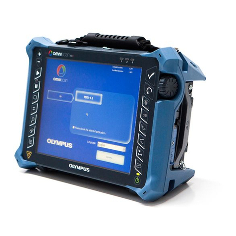
Olympus nortec 600 User manual

DMTA-10040-01EN — Rev. E
February 2018
NORTEC 600
Eddy Current Flaw Detector
User’s Manual
This instruction manual contains essential information on how to use this Olympus product safely and effectively.
Before using this product, thoroughly review this instruction manual. Use the product as instructed.
Keep this instruction manual in a safe, accessible location.

Olympus Scientific Solutions Americas, 48 Woerd Avenue, Waltham, MA 02453, USA
Copyright © 2014, 2015, 2017, 2018 by Olympus. All rights reserved. No part of this
publication may be reproduced, translated, or distributed without the express written
permission of Olympus.
This document was prepared with particular attention to usage to ensure the accuracy of the
information contained therein, and corresponds to the version of the product manufactured
prior to the date appearing on the title page. There could, however, be some differences
between the manual and the product if the product was modified thereafter.
The information contained in this document is subject to change without notice.
Part number: DMTA-10040-01EN
Rev. E
February 2018
Printed in the United States of America
The microSD logo is a trademark of SD-3D, LLC.
All brands are trademarks or registered trademarks of their respective owners and third
party entities.

DMTA-10040-01EN, Rev. E, February 2018
Table of Contents iii
Table of Contents
List of Abbreviations ....................................................................................... ix
Labels and Symbols ........................................................................................... 1
Important Information — Please Read Before Use ..................................... 7
Intended Use .......................................................................................................................... 7
Instruction Manual ................................................................................................................ 7
Instrument Compatibility ..................................................................................................... 8
Repair and Modification ....................................................................................................... 9
Patent Rights Protection ....................................................................................................... 9
Safety Symbols ..................................................................................................................... 10
Safety Signal Words ............................................................................................................. 10
Note Signal Words ............................................................................................................... 11
Safety ..................................................................................................................................... 11
Warnings ............................................................................................................................... 12
Battery Precautions .............................................................................................................. 13
Equipment Disposal ............................................................................................................ 14
CE (European Community) ............................................................................................... 14
WEEE Directive .................................................................................................................... 14
China RoHS .......................................................................................................................... 15
Korea Communications Commission (KCC) ................................................................... 16
EMC Directive Compliance ................................................................................................ 16
FCC (USA) Compliance ...................................................................................................... 16
ICES-001 (Canada) Compliance ........................................................................................ 17
Warranty Information ......................................................................................................... 17
Technical Support ................................................................................................................ 18
Introduction ...................................................................................................... 19

DMTA-10040-01EN, Rev. E, February 2018
Table of Contentsiv
1. Instrument Overview ................................................................................ 21
1.1 Operating Principle ................................................................................................... 21
1.2 Contents of the Case ................................................................................................. 22
1.3 Connectors ................................................................................................................. 23
1.4 Power Requirements ................................................................................................. 26
1.4.1 Charger/Adaptor ............................................................................................ 27
1.4.2 Battery Compartment .................................................................................... 30
1.4.3 Lithium-Ion Battery ....................................................................................... 31
1.4.4 Alkaline Batteries ........................................................................................... 32
1.5 Optional microSD Card Installation ....................................................................... 33
1.6 NORTEC 600 Hardware Features .......................................................................... 34
1.6.1 Hardware Overview ...................................................................................... 35
1.6.1.1 Front Panel and SmartKnob ............................................................... 36
1.6.1.2 Keypad .................................................................................................. 37
1.6.2 Connectors ....................................................................................................... 42
1.6.2.1 Probe and BNC Connectors ............................................................... 42
1.6.2.2 Input/Output (I/O) and VGA OUT Connectors .............................. 42
1.6.2.3 microSD and USB Port ........................................................................ 44
1.6.3 Various Hardware Features .......................................................................... 45
1.6.3.1 Instrument Stand ................................................................................. 45
1.6.3.2 O-Ring Gasket and Membrane Seals ................................................ 46
1.6.3.3 Display Protection ............................................................................... 46
1.6.4 Environmental Ratings .................................................................................. 46
2. Software User Interface ............................................................................ 49
2.1 Starting Up the Instrument ...................................................................................... 49
2.1.1 Navigating the Application Menu ............................................................... 50
2.1.2 Main Inspection Screen ................................................................................. 51
2.2 Selecting from the Menus ........................................................................................ 54
2.3 Displaying All Functions Simultaneously — ALL SETTINGS Menu ............... 54
2.3.1 Using the ALL SETTINGS Menu ................................................................. 55
2.3.2 Special Functions in the ALL SETTINGS Menu ........................................ 56
2.4 Displaying Real-Time Readings ............................................................................. 56
2.4.1 Enabling Real-Time Readings on the Main Inspection Screen ................ 59
2.4.2 Enabling the Real-Time Readings in Full-Screen Mode — FULL NEXT
key .................................................................................................................... 60
3. Initial Setup ................................................................................................ 63
3.1 Setting the User Interface Language and the Decimal Symbol .......................... 63
3.2 Setting the Clock ....................................................................................................... 64
3.3 Changing the Location of Saved Files .................................................................... 64

DMTA-10040-01EN, Rev. E, February 2018
Table of Contents v
3.4 Changing the Display Settings ................................................................................ 65
3.5 Changing the Display Brightness ........................................................................... 66
3.6 Adjusting Auto Erase ............................................................................................... 67
3.7 Selecting the Startup Screen .................................................................................... 67
3.8 Enabling Knobless Entry for Harsh Environments ............................................. 68
4. Control Functions ...................................................................................... 69
4.1 PowerLink .................................................................................................................. 69
4.2 Instrument Controls ................................................................................................. 70
4.2.1 Display ............................................................................................................. 71
4.2.2 Power and Lock Buttons ............................................................................... 71
4.2.3 Direct-Function Keys ..................................................................................... 71
4.2.4 Menu Keys ...................................................................................................... 77
4.2.5 Knob ................................................................................................................. 78
4.2.6 Hidden Function — Screen Capture ........................................................... 78
4.2.7 Knobless Entry ............................................................................................... 78
4.2.8 Ambidextrous Controls ................................................................................. 79
4.2.9 FULL NEXT key ............................................................................................. 80
4.3 Menus ......................................................................................................................... 82
4.3.1 Frequency (FREQ 1) Menu — MAIN FILTER Key ................................... 82
4.3.2 Filter Menu — MAIN FILTER Key .............................................................. 84
4.3.3 Special Menu — MAIN FILTER Key ........................................................... 85
4.3.4 Display Menu — DISP Key .......................................................................... 87
4.3.5 Alarm Menu — ALARM Key ...................................................................... 91
4.3.6 Memory Menu — MEM Key ........................................................................ 92
4.3.7 Memory Text Editor ....................................................................................... 96
4.3.8 Advanced Setup Menu — ADV SETUP Menu Key .................................. 99
4.4 Dual Frequency Menus .......................................................................................... 109
4.4.1 Frequency (FREQ 1) Menu — MAIN FILTER Key ................................. 109
4.4.2 Frequency (FREQ 2) Menu — MAIN FILTER Key ................................. 111
4.4.3 MIX Menu in Dual Frequency — MAIN FILTER Key ........................... 113
4.4.4 Filter Menu in Dual Frequency — MAIN FILTER Key .......................... 114
4.4.5 Special Menu in Dual Frequency — MAIN FILTER Key ....................... 114
4.4.6 Display Menu in Dual Frequency — DISP Key ...................................... 116
4.4.7 ALARM Menu in Dual Frequency — ALARM Key ............................... 118
5. Using the Instrument .............................................................................. 119
5.1 Common NORTEC 600 Applications .................................................................. 120
5.1.1 Detecting Surface-Breaking Cracks — General Purpose Procedure for All
NORTEC 600 Models .................................................................................. 120

DMTA-10040-01EN, Rev. E, February 2018
Table of Contentsvi
5.1.2 Inspecting Fastener Holes with a Rotating Scanner — NORTEC 600S and
NORTEC 600D Models ................................................................................ 126
5.1.3 Detecting Sub-Surface Cracks at Very Low Frequency — All
NORTEC 600 Models ................................................................................... 135
5.1.4 Inspecting Welds on Ferromagnetic Materials — All NORTEC 600
Models ........................................................................................................... 141
5.1.5 Evaluating Paint Thickness on Ferromagnetic Material — All
NORTEC 600 Models ................................................................................... 148
5.1.6 Measuring Conductivity and Nonconductive Coating Thickness —
NORTEC 600C, NORTEC 600S, and NORTEC 600D Models ............... 154
5.1.7 Inspecting Aircraft Wheels — All NORTEC 600 Models ....................... 160
5.1.8 Inspecting Critical Fastener Holes with a Controlled Translation
(Indexing) Scanner — NORTEC 600S and NORTEC 600D Models ..... 166
5.2 Special and Educational Applications ................................................................. 173
5.2.1 Using the Impedance Plane Theory and Display — All NORTEC 600
Models ........................................................................................................... 174
5.2.2 Sorting Metals by Evaluating Conductivity — All NORTEC 600
Models ........................................................................................................... 177
5.2.3 Evaluating Nonconductive Coating (Paint) Thickness — All NORTEC 600
Models ........................................................................................................... 181
5.2.4 Evaluating Metal Thickness and Using Thickness Curve Theory — All
NORTEC 600 Models ................................................................................... 185
5.3 Advanced Dual Frequency Applications ............................................................ 189
5.3.1 Detecting Corrosion Using Dual Frequency to Reduce the Pillowing
Effect — NORTEC 600D Model ................................................................. 190
5.3.2 Detecting Sub-Surface Cracks Using Dual Frequency in a Lap Splice with
Anodized and Alodine Rivets — NORTEC 600D Model ....................... 201
5.3.3 Inspecting Heat Exchanger Tubing Using Dual Frequency —
NORTEC 600D Model ................................................................................. 215
5.4 Heat Exchanger Tubing Applications .................................................................. 228
5.4.1 ECT Pitting, Wear, and Cracks — NORTEC 600D Model ...................... 230
5.4.1.1 Using the Application ....................................................................... 233
5.4.1.2 Displaying Reference Signals .......................................................... 248
5.4.1.3 Using the ALL-IN-1 (Strip Chart) Display .................................... 249
5.4.2 ECT Erosion and Corrosion — NORTEC 600D Model .......................... 251
5.4.3 RFT Pitting and Wear — NORTEC 600D Model ..................................... 256
5.4.3.1 Using the Application ....................................................................... 259
5.4.3.2 Enhancing the Signal with the LO PASS Filter ............................. 268
5.4.3.3 Using the ALL-IN-1 Display ............................................................ 269
5.4.4 RFT Erosion and Corrosion — NORTEC 600D Model ........................... 271
5.4.4.1 Using the Application ....................................................................... 272
5.4.4.2 Using the Overlay Display ............................................................... 277
DMTA-10040-01EN, Rev. E, February 2018
Table of Contents vii
5.4.4.3 Optimizing the Frequency ............................................................... 278
5.4.5 NFT Pitting (Differential) — NORTEC 600D Model .............................. 279
5.4.6 NFT Erosion and Corrosion (Absolute) — NORTEC 600D Model ...... 286
5.5 Alarm Menus ........................................................................................................... 292
5.5.1 Alarm DEFINE Menu .................................................................................. 292
5.5.2 Selecting the Alarm Shape and Position — Alarm 1, 2, and 3 Menus .. 294
5.5.3 SWEEP alarm ................................................................................................ 295
6. NORTEC PC Software ............................................................................ 297
6.1 Importing Files ........................................................................................................ 297
6.2 Capturing a Screen Image Using NORTEC PC .................................................. 300
6.3 Upgrading the Instrument Software Using NORTEC PC ................................ 302
6.4 Upgrading the Instrument Software without NORTEC PC ............................. 305
6.5 Creating a PDF ........................................................................................................ 307
6.6 Issuing Remote Commands to the NORTEC 600 from a PC ............................ 308
6.7 Remotely Controlling the NORTEC 600 from a PC ........................................... 318
6.8 Managing Files on the NORTEC 600 from your PC .......................................... 320
6.9 Unlocking NORTEC 600 Upgrade Options with your PC ............................... 323
6.10 Backing Up the NORTEC 600 Files ...................................................................... 325
6.11 Restoring or Cloning the NORTEC 600 Files ...................................................... 327
7. Maintenance and Troubleshooting ...................................................... 329
7.1 Lithium-Ion Battery ................................................................................................ 329
7.2 Error Messages ........................................................................................................ 330
7.3 Probe Care and Diagnostics .................................................................................. 331
Appendix A: Specifications ......................................................................... 333
A.1 General and Environmental Specifications ......................................................... 333
A.2 Input/Output Specifications .................................................................................. 338
Appendix B: Accessories, Replacement Parts, and Upgrades ............... 341
List of Figures ................................................................................................. 347
List of Tables ................................................................................................... 357
Index ................................................................................................................. 359

DMTA-10040-01EN, Rev. E, February 2018
Table of Contentsviii

DMTA-10040-01EN, Rev. E, February 2018
List of Abbreviations ix
List of Abbreviations
A/C air conditioner
AC alternating current
CD-ROM compact disc read-only memory
DC direct current
ECT eddy current testing
EFUP environment-friendly use period
GB gigabyte
I/O input-output
ID identification
ID internal diameter
IP ingress protection
LCD liquid crystal display
LED light-emitting diode
Li-ion lithium-ion
MIL military
mil one-thousandths of one inch (0.0254 mm)
N/A not applicable
NFT near-field testing
OD outside diameter
OEM original equipment manufacturer
P/N part number
PC personal computer
RFT remote-field testing
SD secure digital (card)

DMTA-10040-01EN, Rev. E, February 2018
Labels and Symbols 1
Labels and Symbols
Safety-related labels and symbols are attached to the instrument at the locations
shown in Figure i-1 on page 1. If any or all of the labels or symbols are missing or
illegible, please contact Olympus.
Figure i‑1 Label attached to the back of the instrument
Instruction and rating label (see Table 1 on page 2)

DMTA-10040-01EN, Rev. E, February 2018
Labels and Symbols2
Figure i‑2 Location of the serial number
Table 1 Content of the rating label
Content
This symbol indicates the location of the membrane vent.
The direct current symbol.
Efficiency of battery chargers specific to California, USA.
Serial number location (see Table 1 on page 2)

DMTA-10040-01EN, Rev. E, February 2018
Labels and Symbols 3
The WEEE symbol indicates that the product must not be
disposed of as unsorted municipal waste, but should be
collected separately.
The regulatory compliance mark (RCM) label indicates that
the product complies with all applicable standards, and has
been registered with the Australian Communications and
Media Authority (ACMA) for placement on the Australian
market.
Seller and user shall be noticed that this equipment is suitable
for electromagnetic equipment for office work (class A) and it
can be used outside home. The MSIP code for the
NORTEC 600 is the following: MSIP-REM-OYN-N600.
The CE marking is a declaration that this product conforms to
all the applicable directives of the European Community. See
the Declaration of Conformity for details. Contact your Olympus
representative for more information.
The China RoHS mark indicates the product’s Environment-
Friendly Use Period (EFUP). The EFUP is defined as the
number of years for which listed controlled substances will not
leak or chemically deteriorate while in the product. The EFUP
for the NORTEC 600 has been determined to be 15 years. Note:
The Environment-Friendly Use Period (EFUP) is not meant to
be interpreted as the period assuring functionality and
product performance.
Table 1 Content of the rating label (continued)

DMTA-10040-01EN, Rev. E, February 2018
Labels and Symbols4
SERIAL The serial number is a nine (9) digit number in the following
format:
yynnnddmm
where:
yy Production year
nnn Unit number manufactured that day
dd Production day
mm Production month
For example, the 130050609 serial number indicates that the
fifth unit (005) was produced on 6 September 2013.
Table 2 Content of the probe adaptor labels
Content
The direct current symbol.
The WEEE symbol indicates that the product must not be
disposed of as unsorted municipal waste, but should be
collected separately.
Table 1 Content of the rating label (continued)
RFT adaptor label
ECT and NFT adaptor label
Part identification label

DMTA-10040-01EN, Rev. E, February 2018
Labels and Symbols 5
The CE marking is a declaration that this product conforms to
all the applicable directives of the European Community. See
the Declaration of Conformity for details. Contact your Olympus
representative for more information.
The China RoHS mark indicates the product’s Environment-
Friendly Use Period (EFUP). The EFUP is defined as the
number of years for which listed controlled substances will not
leak or chemically deteriorate while in the product. The EFUP
for the NORTEC 600 probe cable has been determined to be
15 years. Note: The Environment-Friendly Use Period (EFUP)
is not meant to be interpreted as the period assuring
functionality and product performance.
The warning symbol indicates that the user must read the
user’s manual in order to find out the nature of the potential
hazards and any actions to avoid them.
Part
identification
information
The product’s part number and description.
Table 2 Content of the probe adaptor labels (continued)

DMTA-10040-01EN, Rev. E, February 2018
Labels and Symbols6

DMTA-10040-01EN, Rev. E, February 2018
Important Information — Please Read Before Use 7
Important Information — Please Read Before Use
Intended Use
The NORTEC 600 is designed to perform nondestructive inspections on industrial
and commercial materials.
Do not use the NORTEC 600 for any purpose other than its intended use. It must
never be used to inspect or examine human or animal body parts.
Instruction Manual
This instruction manual contains essential information on how to use this Olympus
product safely and effectively. Before using this product, thoroughly review this
instruction manual. Use the product as instructed.
Keep this instruction manual in a safe, accessible location.
WARNING

DMTA-10040-01EN, Rev. E, February 2018
Important Information — Please Read Before Use8
Some of the details of components illustrated in this manual may differ from the
components installed on your instrument. However, the operating principles remain
the same.
Instrument Compatibility
Only use the NORTEC 600 instrument with the following ancillary equipment:
• Rechargeable lithium-ion (Li-ion) battery pack (Olympus P/N: 600-BAT-L-2
[U8760058])
• Optional stand-alone external battery charger (Olympus P/N: EPXT-EC-X
[U8767043]), where “X” denotes the power cord type (see Table 12 on page 342).
• Charger/adaptor (Olympus P/N: EP-MCA-X), where “X” denotes the power cord
type (see Table 14 on page 343).
See “Accessories, Replacement Parts, and Upgrades” on page 341 for more details
about accessories.
Always use equipment and accessories that meet Olympus specifications. Using
incompatible equipment could cause equipment malfunction and/or damage, or
human injury.
The following rotating scanners are compatible with the NORTEC 600S and
NORTEC 600D instrument models:
• MiniMite
•Spitfire
IMPORTANT
NOTE
CAUTION

DMTA-10040-01EN, Rev. E, February 2018
Important Information — Please Read Before Use 9
• RA-2000 (replaces the RA-19 scanner, which became obsoleted in 2002. The RA-19
scanner is NOT compatible with the NORTEC 500 or NORTEC 600 instrument
series)
•PS5
• GE Hocking MiniDrive
• Rohmann Elotest MR3 scanner
ANY other scanner not listed here has not been tested and is NOT supported at the
time of publication of this manual.
Repair and Modification
The NORTEC 600 does not contain any user-serviceable parts. Opening the
instrument might void the warranty.
In order to prevent human injury and/or equipment damage, do not disassemble,
modify, or attempt to repair the instrument.
Patent Rights Protection
Certain components of Olympus products are patented. For more details, see the
About > Legal Info menu on the NORTEC 600 instrument display.
IMPORTANT
CAUTION

DMTA-10040-01EN, Rev. E, February 2018
Important Information — Please Read Before Use10
Safety Symbols
The following safety symbols might appear on the instrument and in the instruction
manual:
General warning symbol
This symbol is used to alert the user to potential hazards. All safety messages that
follow this symbol shall be obeyed to avoid possible harm or material damage.
Shock hazard caution symbol
This symbol is used to alert the user to potential laser hazards. All safety
messages that follow this symbol shall be obeyed to avoid possible harm or
material damage.
Safety Signal Words
The following safety signal words might appear in the documentation of the
instrument:
The DANGER signal word indicates an imminently hazardous situation. It calls
attention to a procedure, practice, or the like that if not correctly performed or
adhered to will result in death or serious personal injury. Do not proceed beyond a
DANGER signal word until the indicated conditions are fully understood and met.
The WARNING signal word indicates a potentially hazardous situation. It calls
attention to a procedure, practice, or the like that if not correctly performed or
adhered to could result in death or serious personal injury. Do not proceed beyond a
WARNING signal word until the indicated conditions are fully understood and met.
DANGER
WARNING
Other manuals for nortec 600
1
Table of contents
Other Olympus Security Sensor manuals

Olympus
Olympus OmniScan MX2 User manual

Olympus
Olympus EPOCH 650 User manual

Olympus
Olympus Sonic 1200S/HR User manual

Olympus
Olympus EPOCH 600 Assembly instructions

Olympus
Olympus EPOCH 6LT User manual

Olympus
Olympus EPOCH 6LT User manual

Olympus
Olympus Panametrics Epoch 4 Plus User manual

Olympus
Olympus EPOCH 1000 Series User manual

Olympus
Olympus nortec 600 User manual

Olympus
Olympus EPOCH 6LT User manual