manuals.online logo
Brands
  1. Home
  2. •
  3. Brands
  4. •
  5. Alarmtech
  6. •
  7. Security Sensor
  8. •
  9. Alarmtech MC 470 User manual

Alarmtech MC 470 User manual

MC 470 Instruction Manual 4-MC470-01
© 2021 Alarmtech Rev. MC470_2150en Page 1of 2
Detectors
Magnetic Contact
Surface mounting
Datasheet and Instruction Manual MC 470
DESCRIPTION
MC 470 is a high security magnetic contact for surface mount with
protection against magnetic interference and an opening contact. It
can be used in security system and industrial control systems for
protection of doors and windows against unauthorized opening. It
is easy to mount and has 6 screw terminals with wire guards.
MC 470 is certified to EN 50131-2-6:2008 Grade 3, Class I.
CIRCUIT DIAGRAM (SHOWN WITHOUT MAGNETIC FIELD)
Fig. 1. MC 470
Fig. 2. MC 470 with resistors mounted in terminals for balanced
loop
TECHNICAL DATA
Working environment
Wood
Steel
Sabotage distance
max 10 mm
Use accessories a)
Make distance
typ. 24 mm ± 10 %
Use accessories a)
Break distance
typ. 26 mm ± 10 %
Use accessories a)
Contact type
form A, SPST
Switching voltage max.
48 V DC/AC
Switching current max.
400 mA DC/peak AC
Contact rating max.
10 W
Estimated life expectancy
>20 million switching operations at 10 V/4 mA
Environmental class: EN50130-5:2011
Class I
Operating temperature range
+5°C to +40°C
Operating humidity
max. 95% RH
IP Class
IP 43
Housing material
plastic ABS
Dimensions Contact part
65 x 15,6 x 19,6 mm
Magnet part
65 x 15,1 x 16,1 mm
Security grade: EN50131-2-6:2008
Grade 3
Approvals
EN-ST-000205, SBSC 9-201, F&P 10.212-13319,
FG MKT-1019/09, INCERT B-582-1003
a) If mounted on steel, always use additional spacers MC 400-3 and MC 400-4 under contact and magnet and check carefully the distances.
DISTANCE TABLE
The distance in the table below is measured
along the Y-axis when the contact part and the
magnet part is mounted in parallel and the
arrows point to each other.
Distance in
mm
Tolerance
Make
24
± 10%
Break
26
±10%
Sabotage
10
Max
MC 470 Instruction Manual 4-MC470-01
© 2021 Alarmtech Rev. MC470_2150en Page 2of 2
OPERATING PRINCIPLE
MC 470 magnetic contact has two parts: the contact part
with alarm and sabotage reed switches and magnet part.
When correctly mounted the alarm reed switch remains
closed under the force of the magnetic field. Opening the
monitored object increases the distance between the reed
switch and the magnet reduces the influence of the
magnetic field on the reed switch until it opens and activate
an alarm.
MC 470 has extra sabotage reed switches to protect the
contact from sabotage (interference) with an external
magnet. When an external magnet is applied to the contact,
the sabotage reed switches open and activate alarm. The
sabotage switches can also be open when the magnet is too
close. The distance between the contact and the
corresponding magnet, at which the sabotage reed switches
open is called sabotage distance.
Notice. Please mount the contact and magnet so the arrow
point to each other.
Notice. Magnetic contacts should not be installed in the
vicinity of strong magnetic fields or on magnetic material.
INSTALLATION
Contact and magnet should be installed in parallel,
corresponding to each other. Offset will reduce the working
distances and may result in faulty operation or lower
security. Arrows on the contact and magnet inner housings
must point to each other. The contact should be mounted
MOUNTING INSTRUCTIONS
Contact and magnet should be installed in parallel,
corresponding to each other. Offset will reduce the
working distances and may result in faulty operation.
Spacers must be used for installation on ferromagnetic
surfaces on the stationary part of the monitored object (ex.
door frame) and the magnet on the movable part (ex. door
leaf).
For sites where it is impossible to mount the contact
directly, spacers and aluminum brackets are available.
Spacers enable installation of the contact on ferromagnetic
surfaces. Brackets can be used to mount the contact parts
away from a ferromagnetic surface or to solve problems
with aligning the contact with the magnet. Contact and/or
magnet should be screwed to the oval slots in the brackets
and adjusted to a suitable position.
Only non-ferromagnetic screws may be used for mounting
the contact.
For the most adequate distance for mounting, magnetic
part should be placed close to the contact part to get
Sabotage distance, then move away magnetic part to get
minimum Make distance.
After the installation, use an ohmmeter to check the
electrical connections and test the operation of the
magnetic contact.
Warning: Applying excessive force to the housing of the
contact may damage the glass body of the reed switches
inside.
Warning: Appropriate accessories must be used for
installation in ferromagnetic environment.
ORDER INFORMATION
ORDER INFORMATION
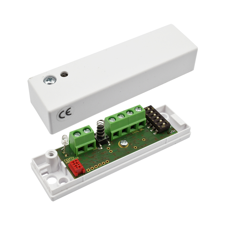
Models available
Description
MC 470
For separate alarm loop and
sabotage loop
Accessories
Model
Description
MC-L
L bracket in Al
MC-Z
Z-bracket in Al
MC 400-3
Extra spacer for contact 7mm
MC 400-4
Extra spacer for magnet 7mm
We reserve the right to changes without notice.

Other Alarmtech Security Sensor manuals

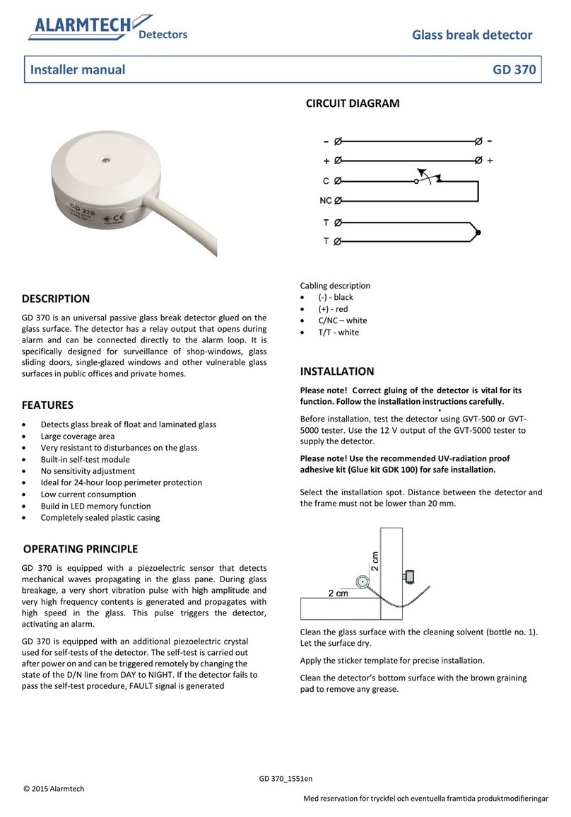
Alarmtech GD 375 Instruction Manual

Alarmtech

Alarmtech GD 375 Instruction Manual

Alarmtech MC 740-E-M14 User manual

Alarmtech

Alarmtech MC 740-E-M14 User manual

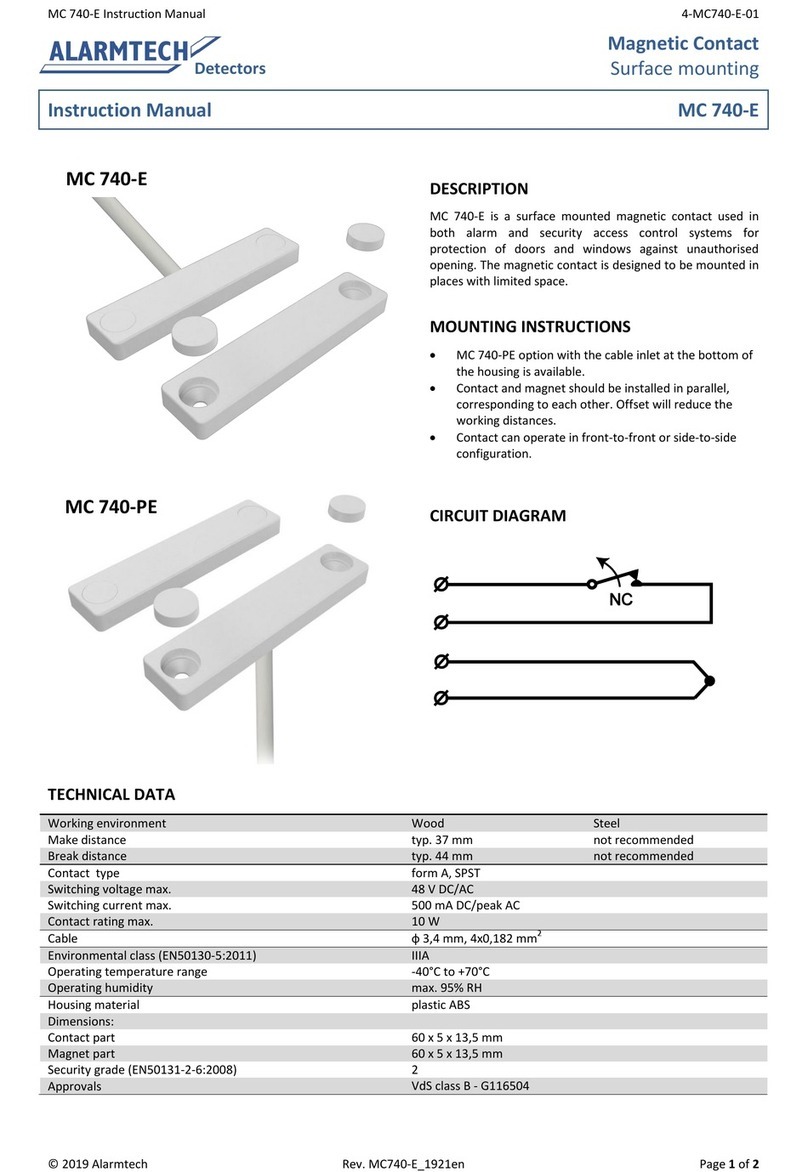
Alarmtech MC 740-E User manual

Alarmtech

Alarmtech MC 740-E User manual

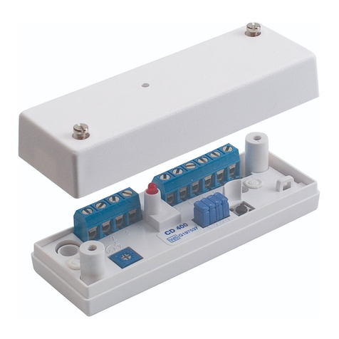
Alarmtech CD 470 User manual

Alarmtech

Alarmtech CD 470 User manual

Alarmtech MC 740-E User manual

Alarmtech

Alarmtech MC 740-E User manual

Alarmtech CD 470 User manual

Alarmtech

Alarmtech CD 470 User manual

Alarmtech GD 370 User guide

Alarmtech

Alarmtech GD 370 User guide

Alarmtech CD 470-I User manual

Alarmtech

Alarmtech CD 470-I User manual

Alarmtech AD 800 Manual

Alarmtech

Alarmtech AD 800 Manual

Alarmtech MC 746-E User manual

Alarmtech

Alarmtech MC 746-E User manual

Alarmtech AD 700 User manual

Alarmtech

Alarmtech AD 700 User manual

Alarmtech MC 340 2x4,7k User manual

Alarmtech

Alarmtech MC 340 2x4,7k User manual

Alarmtech CD 400 User manual

Alarmtech

Alarmtech CD 400 User manual

Alarmtech MC 140 User manual

Alarmtech

Alarmtech MC 140 User manual

Alarmtech MC 472 User manual

Alarmtech

Alarmtech MC 472 User manual

Alarmtech GD 335 User manual

Alarmtech

Alarmtech GD 335 User manual

Alarmtech AD 800-AM Manual

Alarmtech

Alarmtech AD 800-AM Manual

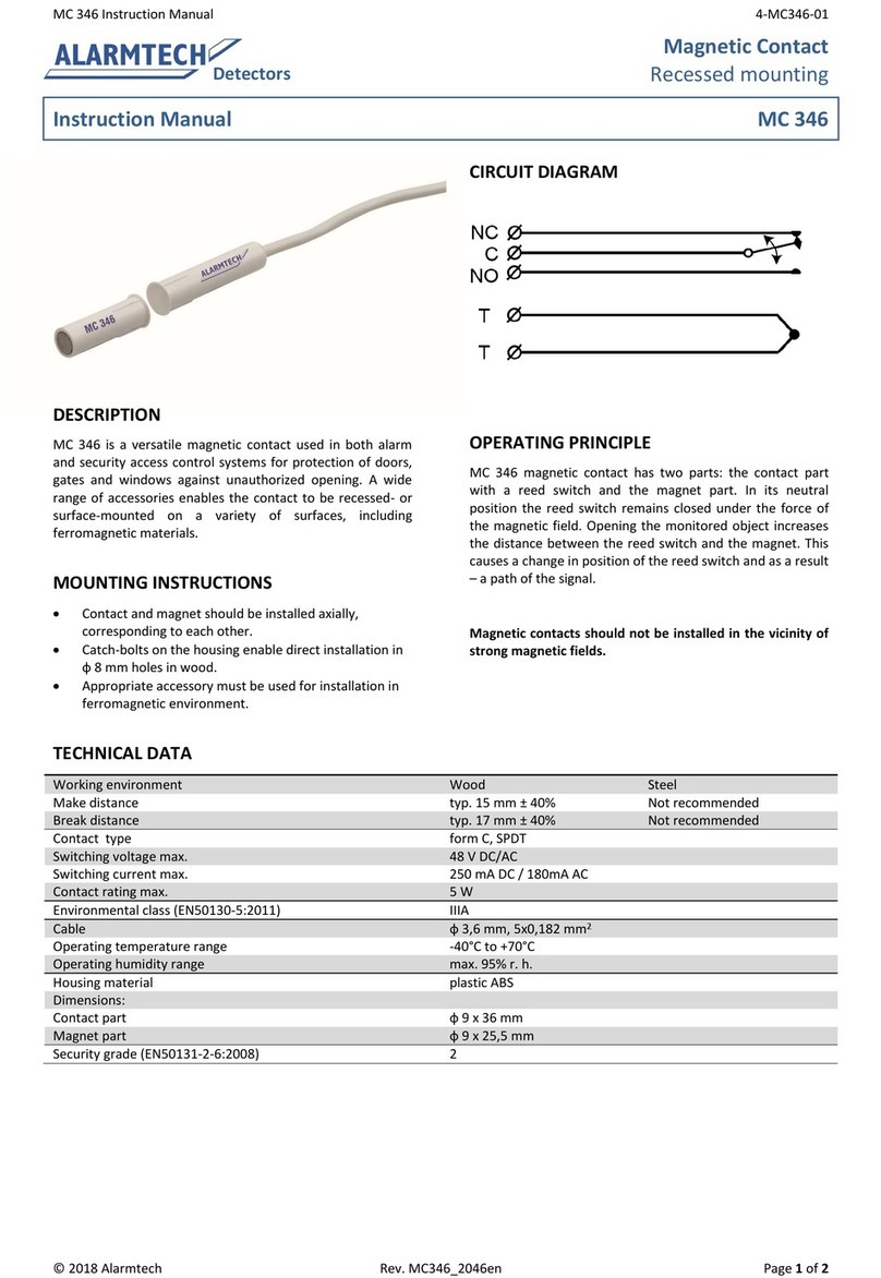
Alarmtech MC 346 User manual

Alarmtech

Alarmtech MC 346 User manual

Popular Security Sensor manuals by other brands

THORLABS SPDMA Operation manual

THORLABS

THORLABS SPDMA Operation manual

Infinite L-COM SRMS-D469-1 user guide

Infinite

Infinite L-COM SRMS-D469-1 user guide

Baumer UNAM 50U6121 manual

Baumer

Baumer UNAM 50U6121 manual

Endress+Hauser USR30 technical information

Endress+Hauser

Endress+Hauser USR30 technical information

Clas Ohlson TSM02 quick start guide

Clas Ohlson

Clas Ohlson TSM02 quick start guide

Uniden R3 user manual

Uniden

Uniden R3 user manual

teko Astra-516 operating manual

teko

teko Astra-516 operating manual

hyfire HFW-MA-05 instructions

hyfire

hyfire HFW-MA-05 instructions

Protean Instrument MPC-900 manual

Protean Instrument

Protean Instrument MPC-900 manual

Assa Abloy Ditec PAS005AP user guide

Assa Abloy

Assa Abloy Ditec PAS005AP user guide

DMP Electronics 1121 Installation sheet

DMP Electronics

DMP Electronics 1121 Installation sheet

IFM Electronic EFECTOR 500 PD70 Series operating instructions

IFM Electronic

IFM Electronic EFECTOR 500 PD70 Series operating instructions

Rielta Pyrone-7i installation guide

Rielta

Rielta Pyrone-7i installation guide

STI 7535MED Quick installation

STI

STI 7535MED Quick installation

AQUALEAK AquaGuard Dual instruction manual

AQUALEAK

AQUALEAK AquaGuard Dual instruction manual

General Monitors FL3112 manual

General Monitors

General Monitors FL3112 manual

Falltech EcoAnchor user manual

Falltech

Falltech EcoAnchor user manual

WABCO 400 606 410 0 user manual

WABCO

WABCO 400 606 410 0 user manual

manuals.online logo
manuals.online logoBrands
  • About & Mission
  • Contact us
  • Privacy Policy
  • Terms and Conditions

Copyright 2025 Manuals.Online. All Rights Reserved.