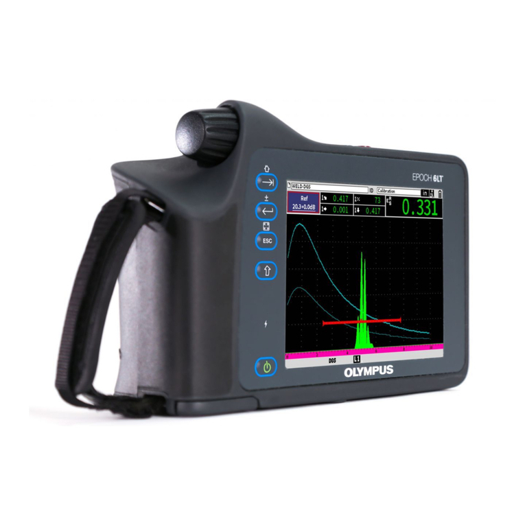
Olympus EPOCH 6LT User manual

DMTA-10084-01EN — Rev. 2
November 2018
EPOCH 6LT
Ultrasonic Flaw Detector
User Interface Guide
This instruction manual contains essential information on how to use this Olympus product safely and effectively.
Before using this product, thoroughly review this instruction manual. Use the product as instructed.
Keep this instruction manual in a safe, accessible location.

Olympus Scientific Solutions Americas, 48 Woerd Avenue, Waltham, MA 02453, USA
Copyright © 2017, 2018 by Olympus. All rights reserved. No part of this publication may be
reproduced, translated, or distributed without the express written permission of Olympus.
This document was prepared with particular attention to usage to ensure the accuracy of the
information contained therein, and corresponds to the version of the product manufactured
prior to the date appearing on the title page. There could, however, be some differences
between the manual and the product if the product was modified thereafter.
The information contained in this document is subject to change without notice.
Part number: DMTA-10084-01EN
Rev. 2
November 2018
Printed in the United States of America
All brands are trademarks or registered trademarks of their respective owners and third
party entities.

DMTA-10084-01EN, Rev. 2, November 2018
Table of Contents
iii
Table of Contents
List of Abbreviations ....................................................................................... ix
Important Information — Please Read Before Use ..................................... 1
Intended Use .......................................................................................................................... 1
Instruction Manual ................................................................................................................ 1
Safety Symbols ....................................................................................................................... 2
Safety Signal Words ............................................................................................................... 2
Note Signal Words ................................................................................................................. 3
Warranty Information ........................................................................................................... 3
Technical Support .................................................................................................................. 4
Introduction ........................................................................................................ 5
1. Hardware User Interface Overview .......................................................... 7
1.1 Shift Key ....................................................................................................................... 8
1.2 ESC Key ........................................................................................................................ 8
1.3 Enter Key ...................................................................................................................... 8
1.4 Tab Key ......................................................................................................................... 8
1.5 Adjustment Knob ........................................................................................................ 9
2. Software User Interface Overview ......................................................... 11
2.1 File Identifier Bar ...................................................................................................... 12
2.2 Gain Adjustment Box ............................................................................................... 12
2.3 Measurement Reading Boxes .................................................................................. 12
2.4 Message Bar ............................................................................................................... 13
2.5 Live A-Scan ................................................................................................................ 13
2.6 Modes ......................................................................................................................... 14
3. Setup Mode ................................................................................................. 17

DMTA-10084-01EN, Rev. 2, November 2018
Table of Contents
iv
3.1 Setup Menu ................................................................................................................ 17
3.1.1 Setup Menu Icons ........................................................................................... 18
3.1.2 Navigating Dialog Boxes and Setup Pages ................................................. 19
4. Inspection Mode ........................................................................................ 23
4.1 Sidebar Menu ............................................................................................................. 24
4.1.1 Sidebar Menu Button Actions ...................................................................... 24
4.1.2 Adjustable Value Buttons .............................................................................. 25
4.1.3 Using the Sidebar Menu and Submenus .................................................... 26
4.2 Shortcut Menus ......................................................................................................... 28
4.2.1 File Identifier Shortcut Menu ....................................................................... 28
4.2.2 Measurement Reading Shortcut Menu ....................................................... 29
4.2.3 Gain Adjustment Shortcut Menu ................................................................. 31
5. Setup Pages ................................................................................................. 33
5.1 Opening a Setup Page .............................................................................................. 34
5.2 Using the Virtual Keypad ........................................................................................ 35
5.3 File Management Pages ............................................................................................ 37
5.4 Instrument Settings Pages ........................................................................................ 37
5.4.1 User Keys Setup Page .................................................................................... 37
5.4.2 Display Setup Page ........................................................................................ 41
5.4.3 Measurement Setup Page .............................................................................. 44
5.4.4 Instrument Setup Page .................................................................................. 50
5.4.5 Software Options Setup Page ....................................................................... 52
5.4.6 Clock Setup Page ............................................................................................ 52
5.4.7 Resets Setup Page ........................................................................................... 53
5.4.8 Wi-Fi Networks Setup Page .......................................................................... 54
5.5 Instrument Info Setup Pages ................................................................................... 54
5.5.1 About Setup Page ........................................................................................... 54
5.5.2 Upgrade Setup Page ...................................................................................... 55
5.5.3 Regulatory Setup Page .................................................................................. 56
5.5.4 License Setup Page ......................................................................................... 56
5.5.5 Legal Setup Page ............................................................................................ 57
5.5.6 Diagnostic Test Setup Page ........................................................................... 57
6. Pulser/Receiver Adjustments .................................................................. 59
6.1 Adjusting the Gain (System Sensitivity) ................................................................ 59
6.1.1 Using the Auto XX% Feature ........................................................................ 60
6.1.2 Setting Reference Gain and Scanning Gain ................................................ 60
6.2 Selecting and Adjusting the Pulser ........................................................................ 62
6.2.1 Energy (Voltage) ............................................................................................. 63

DMTA-10084-01EN, Rev. 2, November 2018
Table of Contents
v
6.2.2 Damping .......................................................................................................... 64
6.2.3 Pulser Type ...................................................................................................... 64
6.2.4 Pulser Frequency ............................................................................................ 65
6.2.5 Test Modes ...................................................................................................... 65
6.2.6 Pulse Repetition Frequency (PRF) ............................................................... 66
6.3 Adjusting the Receiver ............................................................................................. 67
6.3.1 Digital Receiver Filters .................................................................................. 68
6.3.2 Waveform Rectification ................................................................................. 69
6.3.3 Reject Parameter ............................................................................................. 69
7. Gates ............................................................................................................. 71
7.1 Activating the Gates ................................................................................................. 71
7.2 Measurement Gates 1 and 2 .................................................................................... 72
7.3 Quickly Adjusting Basic Gate Parameters ............................................................ 73
7.4 Gate Measurement Modes ....................................................................................... 75
7.5 Viewing Measurement Readings ............................................................................ 78
7.6 Gate Tracking and Echo-to-Echo Measurements ................................................. 79
7.7 Time-of-Flight Mode ................................................................................................ 80
7.8 Zooming in on a Gate ............................................................................................... 81
7.9 Gate Alarms ............................................................................................................... 82
7.9.1 Threshold Alarms .......................................................................................... 82
7.9.2 Minimum Depth Alarm ................................................................................ 83
7.10 Peak Memory ............................................................................................................. 85
7.11 Peak Hold ................................................................................................................... 86
7.12 Freeze .......................................................................................................................... 87
8. Calibration ................................................................................................... 89
8.1 Basic Setup ................................................................................................................. 89
8.2 Calibration Modes .................................................................................................... 92
8.2.1 Straight Beam Modes ..................................................................................... 92
8.2.2 Angle Beam Modes ........................................................................................ 93
8.3 Calibration Procedure .............................................................................................. 93
9. Data Logger ............................................................................................... 101
9.1 Data File Types ........................................................................................................ 102
9.1.1 Incremental File Type .................................................................................. 102
9.1.2 Calibration File Type ................................................................................... 103
9.1.3 2-D Matrix Grid File Type ........................................................................... 103
9.2 Data Logger Storage Capacity .............................................................................. 103
9.3 Saving Data to Active Files .................................................................................... 103
9.4 Data Logger Setup Pages ....................................................................................... 104

DMTA-10084-01EN, Rev. 2, November 2018
Table of Contents
vi
9.4.1 Create ............................................................................................................. 105
9.4.2 File .................................................................................................................. 107
9.4.3 Manage .......................................................................................................... 117
9.4.4 Memo ............................................................................................................. 122
9.4.5 Backup|Restore ............................................................................................ 127
9.5 Grid View ................................................................................................................. 130
9.5.1 Activating the Grid View ............................................................................ 130
9.5.2 Configuring the Grid ................................................................................... 131
9.5.3 Using the Grid .............................................................................................. 132
9.6 Video Recorder ........................................................................................................ 135
9.6.1 Activating the Video Recorder ................................................................... 135
9.6.2 Recording and Saving Video ...................................................................... 136
9.6.3 Working with Video Files ........................................................................... 139
10. Wi-Fi Networks ........................................................................................ 145
10.1 Connecting to a Wireless LAN (Wi-Fi) Network ............................................... 145
10.2 Adding a Wireless LAN (Wi-Fi) Network ........................................................... 149
11. Software Features and Options ............................................................. 151
11.1 Defining Licensed and Unlicensed Software Features ...................................... 151
11.2 Activating Software Options ................................................................................. 152
11.3 Dynamic DAC/TCG ................................................................................................ 153
11.3.1 Enabling the DAC/TCG Feature ................................................................ 154
11.3.2 Applying Reference Correction ................................................................. 155
11.3.3 Building a DAC Curve in Standard or ASME III Mode ......................... 156
11.3.4 DAC Inspection Mode ................................................................................. 162
11.3.5 Gain Adjustment Options ........................................................................... 164
11.3.6 JIS DAC .......................................................................................................... 169
11.3.7 Custom DAC Curves ................................................................................... 170
11.4 DGS/AVG ................................................................................................................. 172
11.4.1 Enabling the DGS/AVG Option .................................................................. 173
11.4.2 Curve-Adjustment Options ........................................................................ 177
11.4.3 Transfer Correction ...................................................................................... 177
11.4.4 DGS/AVG Curve Gain ................................................................................. 178
11.4.5 Registration Level Adjustment ................................................................... 179
11.4.6 Relative Attenuation Measurement ........................................................... 180
11.5 AWS D1.1/D1.5 Weld Rating Software ................................................................ 181
11.5.1 Enabling the AWS D1.1 Option .................................................................. 182
11.5.2 Scanning Gain ............................................................................................... 185
11.5.3 Calculating A and C Values ........................................................................ 186
11.6 Back Wall Echo Attenuator .................................................................................... 186
DMTA-10084-01EN, Rev. 2, November 2018
Table of Contents
vii
11.6.1 Enabling the BEA Option ............................................................................ 187
11.6.2 Operating the BEA ....................................................................................... 188
11.7 Corrosion Module ................................................................................................... 189
11.7.1 Key Features ................................................................................................. 190
11.7.2 Corrosion Module Modes ........................................................................... 191
11.7.3 Corrosion Module Activation and Setup ................................................. 194
List of Figures ................................................................................................. 211
List of Tables ................................................................................................... 215
Index ................................................................................................................. 217

DMTA-10084-01EN, Rev. 2, November 2018
Table of Contents
viii

DMTA-10084-01EN, Rev. 2, November 2018
List of Abbreviations
ix
List of Abbreviations
AGC automatic gain control
ASME American Society of Mechanical Engineers
AVG abstand verstärkung größe
AWS American Welding Society
BEA back wall echo attenuator
CSC curved surface correction
DAC distance-amplitude correction
DGS distance gain size
FSH full-screen height
JIS Japanese Industrial Standard
MEM memory
NDT ultrasonic nondestructive testing
OS overshoot
PK peak
PRF pulse repetition frequency
SDH side-drilled hole
TCG time-corrected gain
TOF time-of-flight
UI software user interface

DMTA-10084-01EN, Rev. 2, November 2018
List of Abbreviations
x

DMTA-10084-01EN, Rev. 2, November 2018
Important Information — Please Read Before Use
1
Important Information — Please Read Before Use
Intended Use
The EPOCH 6LT is designed to perform nondestructive inspections on industrial and
commercial materials.
Do not use the EPOCH 6LT for any purpose other than its intended use. It must never
be used to inspect or examine human or animal body parts.
Instruction Manual
This instruction manual contains essential information on how to use this Olympus
product safely and effectively. Before using this product, thoroughly review this
instruction manual. Use the product as instructed.
Keep this instruction manual in a safe, accessible location.
Some of the details of software images in this manual may differ from your
instrument’s software display. However, the principles remain the same.
WARNING
IMPORTANT

DMTA-10084-01EN, Rev. 2, November 2018
Important Information — Please Read Before Use
2
Safety Symbols
The following safety symbols might appear on the instrument and in the instruction
manual:
General warning symbol
This symbol is used to alert the user to potential hazards. All safety messages that
follow this symbol shall be obeyed to avoid possible harm or material damage.
Shock hazard caution symbol
This symbol is used to alert the user to potential electric shock hazards. All safety
messages that follow this symbol shall be obeyed to avoid possible harm.
Safety Signal Words
The following safety signal words might appear in the documentation of the
instrument:
The DANGER signal word indicates an imminently hazardous situation. It calls
attention to a procedure, practice, or the like that if not correctly performed or
adhered to will result in death or serious personal injury. Do not proceed beyond a
DANGER signal word until the indicated conditions are fully understood and met.
The WARNING signal word indicates a potentially hazardous situation. It calls
attention to a procedure, practice, or the like that if not correctly performed or
adhered to could result in death or serious personal injury. Do not proceed beyond a
WARNING signal word until the indicated conditions are fully understood and met.
DANGER
WARNING

DMTA-10084-01EN, Rev. 2, November 2018
Important Information — Please Read Before Use
3
The CAUTION signal word indicates a potentially hazardous situation. It calls
attention to a procedure, practice, or the like that if not correctly performed or
adhered to may result in minor or moderate personal injury, material damage,
particularly to the product, destruction of part or all of the product, or loss of data. Do
not proceed beyond a CAUTION signal word until the indicated conditions are fully
understood and met.
Note Signal Words
The following note signal words could appear in the documentation of the
instrument:
The IMPORTANT signal word calls attention to a note that provides information that
is important or essential to the completion of a task.
The NOTE signal word calls attention to an operating procedure, practice, or the like,
that requires special attention. A note also denotes related parenthetical information
that is useful, but not imperative.
The TIP signal word calls attention to a type of note that helps you apply the
techniques and procedures described in the manual to your specific needs, or that
provides hints on how to effectively use the capabilities of the product.
Warranty Information
Olympus guarantees your Olympus product to be free from defects in materials and
workmanship for a specific period, and in accordance with conditions specified in the
Olympus Scientific Solutions Americas Inc. Terms and Conditions available at
http://www.olympus-ims.com/en/terms/.
CAUTION
IMPORTANT
NOTE
TIP

DMTA-10084-01EN, Rev. 2, November 2018
Important Information — Please Read Before Use
4
The Olympus warranty only covers equipment that has been used in a proper
manner, as described in this instruction manual, and that has not been subjected to
excessive abuse, attempted unauthorized repair, or modification.
Inspect materials thoroughly on receipt for evidence of external or internal damage
that might have occurred during shipment. Immediately notify the carrier making the
delivery of any damage, because the carrier is normally liable for damage during
shipment. Retain packing materials, waybills, and other shipping documentation
needed in order to file a damage claim. After notifying the carrier, contact Olympus
for assistance with the damage claim and equipment replacement, if necessary.
This instruction manual explains the proper operation of your Olympus product. The
information contained herein is intended solely as a teaching aid, and shall not be
used in any particular application without independent testing and/or verification by
the operator or the supervisor. Such independent verification of procedures becomes
increasingly important as the criticality of the application increases. For this reason,
Olympus makes no warranty, expressed or implied, that the techniques, examples, or
procedures described herein are consistent with industry standards, nor that they
meet the requirements of any particular application.
Olympus reserves the right to modify any product without incurring the
responsibility for modifying previously manufactured products.
Technical Support
Olympus is firmly committed to providing the highest level of customer service and
product support. If you experience any difficulties when using our product, or if it
fails to operate as described in the documentation, first consult the user’s manual, and
then, if you are still in need of assistance, contact our After-Sales Service. To locate the
nearest service center, visit the Service Centers page at: http://www.olympus-
ims.com.

DMTA-10084-01EN, Rev. 2, November 2018
Introduction
5
Introduction
The EPOCH 6LT is a portable ultrasonic nondestructive testing (NDT) instrument
designed primarily for inspections requiring high portability, such as rope access, and
detection of flaw conditions in welds, pipes, turbine blades, and other structural and
industrial materials. The instrument can be used both indoors and outdoors.
The EPOCH 6LT offers advanced conventional ultrasonic performance featuring a
large dynamic range and superior measurement resolution. The full color
liquid-crystal display provides a resolution of 640 × 480 pixels with transflective
technology for superior visibility. The software user interface (UI) provides an
intuitive way to access the full functionality of the instrument.

DMTA-10084-01EN, Rev. 2, November 2018
Introduction
6

DMTA-10084-01EN, Rev. 2, November 2018
Hardware User Interface Overview
7
1. Hardware User Interface Overview
The EPOCH 6LT hardware keys and adjustment knob are used to control the software
user interface. The hardware keys are located on the front panel of the instrument.
The adjustment knob is located on the left side of the instrument (see Figure 1-1 on
page 7).
Figure 1-1 EPOCH 6LT front panel
UI keys
Adjustment
knob

DMTA-10084-01EN, Rev. 2, November 2018
Chapter 1
8
1.1 Shift Key
The Shift key ( ) is used to activate the second function, changing the way the
ESC, Enter, and Tab keys function.
1.2 ESC Key
The ESC key ( ) is used to move the focus to the previous menu in the user
interface (UI). The Shift ( ), ESC ( ) key sequence changes the display
mode ( ) of the UI.
1.3 Enter Key
The Enter key ( ) is used to accept a highlighted parameter (selected with the
adjustment knob). The Shift ( ), Enter ( ) key sequence switches between
coarse and fine adjustment ( ) of the highlighted parameter with the adjustment
knob.
1.4 Tab Key
The Tab key ( ) moves the focus to and selects the next element in the UI for an
action. In certain menus, the Tab key ( ) moves the focus to the next icon or
button. The Shift ( ), Tab ( ) key sequence immediately returns to the
live A-scan display from any level of menu, dialog box, or setup page.

DMTA-10084-01EN, Rev. 2, November 2018
Hardware User Interface Overview
9
1.5 Adjustment Knob
The adjustment knob increases or decreases the value of the highlighted adjustable
parameter (see Figure 1-2 on page 9). The Shift ( ), Enter ( ) key
sequence switches the adjustment knob between coarse and fine adjustment of the
highlighted parameter.
The adjustment knob can also be used to move the focus to the next icon, button, or
data element.
Figure 1-2 Adjustment knob

DMTA-10084-01EN, Rev. 2, November 2018
Chapter 1
10
Other manuals for EPOCH 6LT
2
Table of contents
Other Olympus Security Sensor manuals

Olympus
Olympus EPOCH 1000 Series User manual

Olympus
Olympus EPOCH 600 Assembly instructions

Olympus
Olympus OmniScan X3 User manual

Olympus
Olympus nortec 600 User manual

Olympus
Olympus EPOCH 6LT User manual

Olympus
Olympus Panametrics Epoch 4 Plus User manual

Olympus
Olympus Sonic 1200S/HR User manual

Olympus
Olympus EPOCH 6LT User manual

Olympus
Olympus EPOCH 650 User manual

Olympus
Olympus OmniScan MX2 User manual