manuals.online logo
Brands
  1. Home
  2. •
  3. Brands
  4. •
  5. Omega
  6. •
  7. Cooktop
  8. •
  9. Omega OG60XA User manual

Omega OG60XA User manual

installation
and operating
instructions
OG60XA
Cooktop
Dear customer,
We thank you and congratulate you on
your choice.
This new carefully designed product,
manufactured with the highest quality
materials, has been carefully tested to sa-
tisfy all your cooking demands.
We would therefore request you to read
and follow these easy instructions which
will allow you to obtain excellent results
right from the start.
May we wish you all the very best with
your modern appliance!
THE MANUFACTURER
APPLIANCE IS CONCEIVED FOR DOMESTIC USE
ONLY. THE MANUFACTURER SHALL NOT IN ANY
WAY BE HELD RESPONSIBLE FOR WHATEVER
INJURIES OR DAMAGES ARE CAUSED BY
INCORRECT INSTALLATION OR BY UNSUITABLE,
WRONG OR ABSURD USE.
11
USER CHARACTERISTICS
GAS BURNERS
FEED BURNER Ø INJECTORS THÉRMAL CAPACITY CONSUMPTION
TYPE PRESSURE mbar 1/100 mm W
fast 155/130 3000 286
Natural gas semifast 115/105 1750 167
G20 10/20 auxiliary 90/83 1000 95
wok 175/135 3500 333
fish 155/130 3000 286
fast 85/92 3000 218
LPG semifast 65/70 1750 127
G30/G31 28-30/27.5 auxiliary 50/55 1000 73
wok 92/105 3500 254
fish 85/92 3000 218
fast 270 3000 680
Towngas semifast 200 1750 398
G110 8-10 auxiliary 150 1000 227
wok 310/340 * 3500 794
fish 290 3000 680
ELECTRICAL PLATES
FEED TYPE W ADJUSTMENT
normal
Ø 145 - Ø 180 1000 - 1500 commutator (0÷6)
energy regulator (0÷11)
fast
Ø 145 - Ø 180 1500 - 2000
VITROCERAMIC HEATING ELEMENTS
FEED TYPE W ADJUSTMENT
triple-circuit radiant
Ø 145 - Ø 180 1200 - 1700 commutator (0÷6)
single-circuit radiant
Ø 145 - Ø 180 1200 - 1700 energy regulator (0÷11)
mixed-circuit radiant/halogen
Ø 145 - Ø 180 1200 - 1800 energy regulator (0÷11)
duble-circuit oval radiant
Ø 145 x 300 2000 commutator (0÷4)
g/h l/h
l/h
~230 V
~230 V
*SAFETY VALVES
-The appliance is not intended for use by young children or infirm
persons without supervision;
-Young children should be supervised to ensure that they do not play
with the appliance.
- If the supply cord is damaged, it must be replaced by the manufacturer
or its service agent or a similarly qualified person in order to avoid a
hazard
-If a stationary appliance is not provided with a supply cord and a plug
or with other means for disconnection from the supply having an air
gap contact separation in all active (phase) conductors, the instructions
shall state that such means for disconnection shall be incorporated in
the fixed wiring according to the wiring rules.
3
Fig. 1
wok Ø 20-32
fast Ø 20-26
semifast Ø 14-20
auxiliary Ø 10-14
INSTRUCTIONS FOR USE
FOR VITROCERAMIC HOBS SEE ADDITIONAL INSTRUCTIONS
Installation
All the operations concerned with the installation (electrical connection) must be
carried out by qualified technicians, in terms with the standards in force.
For specific instructions, kindly read the part reserved for the installation technician.
Use
Gas burners (Fig. 1-1a-1b).
The ignition of the gas burner is carried out by putting a small flame to the upper part
holes of the burner, pressing and rotating the corresponding knob in an anti-clockwise
manner, until the maximum position has coincided with the marker. When the gas
burner has been turned on, adjust the flame according to need. The minimum position
is found at the end of the anti-clockwise rotation direction.
In models with automatic ignition, operate the knob as described above, pressing
simultaneously, the corresponding push-button. The electric spark between the
ignition plug and the burner provides the ignition of the burner itself. After ignition,
immediately release the push-button and adjust the flame according to need.
To start the burner in models equipped with a thermoelectric resistance keep the knob
pressed hard for 10 seconds, as described above, after placing it on its maximum value.
After releasing the knob, make sure the burner is actually lit.
N.B. - we recommend the use of pots and pans with a diameter matching that of the
burner, thus preventing the flame from escaping from the bottom part and
surrounding the pot
- do not leave any empty pots or pans on the fire
- do not use any tools for grill-cooking on Crystal hobs.
When cooking is finished, it is also a good norm to close the main gas pipe tap and
cylinder.
GAS
10
Fig. 7
be required, it will be necessary to interpose an omnipolar switch with minimum
aperture between the 3 mm. contacts, dimensioned to bear the plate load and it must
follow the standards in force (the yellow/green earth cable must not be interrupted by
the switch). The plug or omnipolar switch must be easily reached on the installed
equipment.
The manufacturers decline any responsibility in the event of non-compliance with
what is described above and the accident prevention norms not being respected and
followed.
Adaptation to various types of gas
(Fig. 8-9) Should the appliance be pre-set for a different type of gas than that available,
proceed as follows:
• replace the injectors (Fig. 7) with the corresponding type of gas to be used (see table
"Uses characteristics").
• to adjust to the minimum, use a screwdriver on the screw placed on the tap (Fig. 8)
after turning the tap to its minimum position. For LPG (butane/propane) screw
tight.
Fig. 9
Fig. 8
CABLE-CLAMP
4
Fig. 1a
9
INSTRUCTIONS FOR THE INSTALLER
Installation
These Instructions are for the qualified technician, as a guide to the installation,
adjustment and maintenance, according to the laws and standards in force. Any of
these operations must always be carried out when the appliance has been disconnected
from the electric system.
Installation (Gas)
This appliance is not provided with a combustion product discharge. It is
recommended that it be installed in sufficiently aerated places, in terms of the laws
in force. The quantity of air which is necessary for combustion must not be below
2.0 m3/h for each kW of installed power.
See table of burner power.
Positioning
(Fig. 5). The appliance can be fitted into a working area as illustrated on the
corresponding figure.
Apply the seal provided over the whole of the area perimeter.
Gas connection
(Fig. 6) Connect the appliance to the gas cylinder or to the installation according to the
prescribed standards in force, and ensure beforehand, that the appliance matches the
type of gas available. Otherwise, see "Adaptation to various types of gas".
Furthermore, check that the feed pressure falls within the values described on the
table: "User chacteristics".
Rigid/semi rigid metal connection
Carry out the connection with fittings and metal pipes (even flexible pipes) so as to
obtain counter stress the inner parts of the appliance.
N.B. - when the installation has been carried out, check the perfect sealing of the entire
connection system, by using a soapy solution.
Electrical connection
(Fig. 7) Prior to carrying out the electrical connection, please ensure that:
• the plant characteristics are such as to follow what is indicated on the matrix plate
placed at the bottom of the working area;
• that the plant is fitted with an efficient
earth connection, following the standards
and law provisions in force. The earth
connection is compulsory in terms of the
law.
Should there be no cable and/or plug on
the equipment, use suitable absorption
material for the working temperature as
well, as indicated on the matrix plate. Un-
der no circumstance must the cable reach a
temperature above 50°C of the ambient
temperature.
Should a direct connection to the network
Fig. 6
ISO 7/1
ISO 228/1 (FR)
5
Fig. 1 b
8
use of electrical plates - Vitroceramic Heating elements
commutator energy heat
cooking methods
regulator intensity
11- 2 slight melting of fats etc.; heat small quantities of liquid
23- 4 mild
heating of medium quantities of liquid; puddings, long-cooking sauces
35- 6 slow defreezing - heat large quantities of liquid; cooking below
boiling temperature
47- 8 medium tender roasts; cooking at boiling temperature
59- 10 high roasts - boiled food; pan-frying of meats
6 10 - 11 burning heat bring large quantities of liquid to boil; fry
Fig. 5
WARNING: CRYSTAL HOBS
DO NOT TIGHTEN SCREW ‘A’ EXCESSIVELY, ONE TURN MAX WILL BE SUFFICIENT, AFTER CORRECTLY FITTING SHAFT ‘B’ INTO PLACE, AS SHOWN
IN THE PICTURE. ENSURE THAT THE SUPPORTING SURFACE IS PERFECTLY EVEN. FIT THE APPROPRIATE EXPANDED SEAL. CRYSTAL HOBS MUST
NOT BE SUBJECTED TO STRAINS CAUSED BY UNEVEN SUPPORTING SURFACES.
6
Vitroceramic Heating elements
Electrical plates
(Figg. 2-3-1a-1b). Rotate the knob towards the position required for cooking and bear
in mind that the higher the number, the higher the heat output. See table "use of
electrical plates".
The pilot light on the stove panel level signals that the plate is "on".
Some types of pilot lights will maintain some slight luminescence even after
disconnection. That is quite normal.
N.B.: When using electrical elements/plates, we recommend flat bottom recipients
with a diameter equal or slightly larger than that of the plate itself.
• avoid liquid overflow. Therefore, after boiling or heating liquids, reduce the heat
output;
• do not leave the electrical elements/plates on with empty pots and pans;
•when cooking is finished, rotate the knob back into closing and/or disconnected
position.
In the event of even a slight fracture on the cooking vitroceramic surface, disconnect
the electric power supply immediately.
Maintenance
Gas/Electric
Prior to any operation, disconnect the appliance from the electrical system.
For long-life to the equipment, a general cleaning operation must take place
periodically, bearing in mind the following:
•the glass, steel and/or enamelled parts must be cleaned with suitable non-abrasive or
Fig. 2
ELECTRIC
PLATES
SWITCHED OFF
VITROCERAMIC HEATING ELEMENTS
Fig. 3
7
Fig. 3a Fig. 4
corrosive products (found on the market). Avoid chlorine-base products (bleach, etc.);
• avoid leaving acid or alkaline substances on the working area (vinegar, salt, lemon
juice, etc.).
• the wall baffle and the small covers (mobile parts of the burner) must be washed
frequently with boiling water and detergent, taking care to remove every possible
encrustation. Dry carefully and check that none of the burner holes is fully or
partially clogged;
• the electrical parts are cleaned with a damp cloth and are lightly greased with
lubricating oil when still warm.
• the stainless steel grids of the working area, after having been heated, take on a
bluish tint which does not deteriorate the quality. To bring colour back to its original
state, use a slightly abrasive product.
N.B.- Cleaning of the taps must be carried out by qualified personnel, who must be
consulted
in case of any functioning anomaly.
Check periodically the state of conservation of the flexible gas feed pipe. In case of
leakage, call immediately the qualified technicians for its replacement.
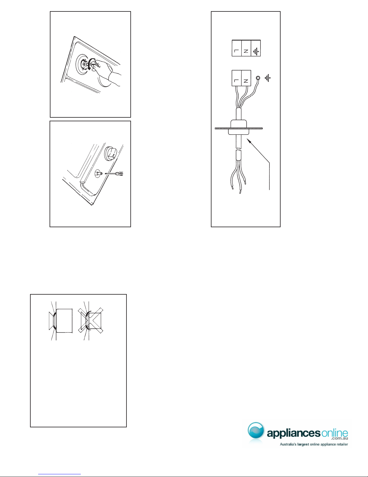
Vitroceramic
Fig. 3a) First of all remove stray food bits and grease drops from the cooking surface
with the special scraper (fig. 4). Then clean the hot area as best as possible with SIDOL,
STAHLFIX or other similar products with a papertowel, then rinse again with water
and dry with a clean cloth.
Pieces of aluminum foil and plastic material which have inadvertently melted or sugar
remains or highly sacchariferous food have to be removed immediately from the hot
cooking area with the special scraper (fig. 4). This is to avoid any possible damage to
the surface of the top.
Under no circumstances should abrasive sponges or irritating chemical detergents be
used such as oven sprays or spot removers.
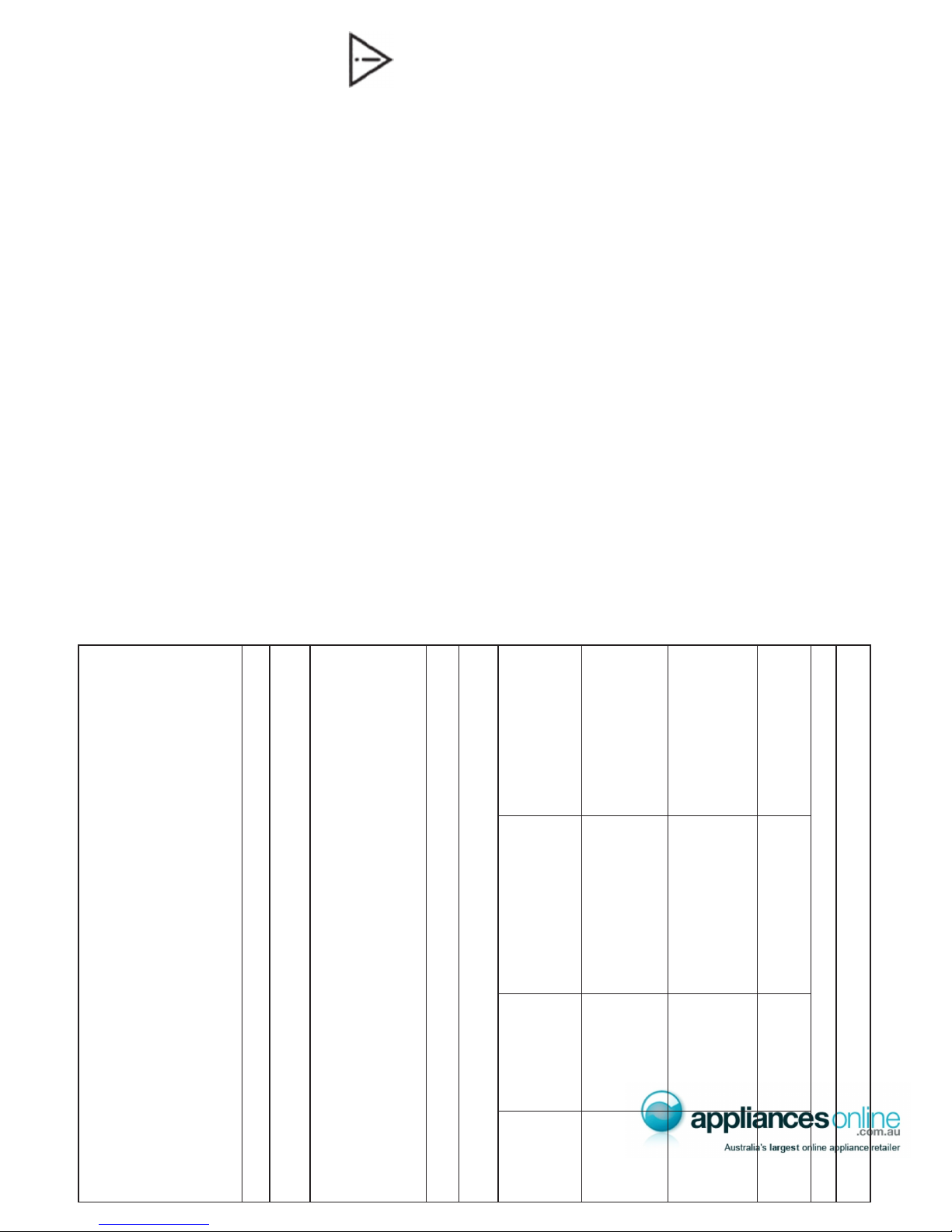
Battery replacement (Fig. 4)
Unscrew plug and replace old
battery.

Other manuals for OG60XA

1

Other Omega Cooktop manuals

Omega OCC64KZTGG User manual

Omega

Omega OCC64KZTGG User manual

Omega OCG63X User manual

Omega

Omega OCG63X User manual

Omega OCI64 User manual

Omega

Omega OCI64 User manual

Omega OCG61X Guide

Omega

Omega OCG61X Guide

Omega OC64BA User manual

Omega

Omega OC64BA User manual

Omega OG72XA User manual

Omega

Omega OG72XA User manual

Omega OC64KZ User manual

Omega

Omega OC64KZ User manual

Omega OCG95XTGG User manual

Omega

Omega OCG95XTGG User manual

Omega OCI64PP User manual

Omega

Omega OCI64PP User manual

Omega OCI64Z User manual

Omega

Omega OCI64Z User manual

Omega OCC90TZ User manual

Omega

Omega OCC90TZ User manual

Omega OG91XA User manual

Omega

Omega OG91XA User manual

Omega OCG32XCOM User manual

Omega

Omega OCG32XCOM User manual

Omega OG61XA User manual

Omega

Omega OG61XA User manual

Omega OCG60X Manual

Omega

Omega OCG60X Manual

Omega MC-HF645 User manual

Omega

Omega MC-HF645 User manual

Omega OI64MZ Manual

Omega

Omega OI64MZ Manual

Omega OC64XA User manual

Omega

Omega OC64XA User manual

Omega OCC70TZ User manual

Omega

Omega OCC70TZ User manual

Omega OG63XA User manual

Omega

Omega OG63XA User manual

Omega OCG905FX Manual

Omega

Omega OCG905FX Manual

Omega OG30XA User manual

Omega

Omega OG30XA User manual

Omega OC64TB User manual

Omega

Omega OC64TB User manual

Omega OC64TXA User manual

Omega

Omega OC64TXA User manual

Popular Cooktop manuals by other brands

KitchenAid KECC506RBL01 parts list

KitchenAid

KitchenAid KECC506RBL01 parts list

DCS CDU-304 installation instructions

DCS

DCS CDU-304 installation instructions

Gaggenau VI 414 613 use and care manual

Gaggenau

Gaggenau VI 414 613 use and care manual

Lumme LU-3629 user manual

Lumme

Lumme LU-3629 user manual

Empava EMPV-36EC01 Instruction manual / installation manual

Empava

Empava EMPV-36EC01 Instruction manual / installation manual

MBM FTBE74A Installation and use instruction

MBM

MBM FTBE74A Installation and use instruction

Optimum PK-2260 operating instructions

Optimum

Optimum PK-2260 operating instructions

Electrolux EW36IC60LB1 Use & care guide

Electrolux

Electrolux EW36IC60LB1 Use & care guide

Sears 790.32433900 Repair parts list

Sears

Sears 790.32433900 Repair parts list

Cadco CDR-1TFB Specification sheet

Cadco

Cadco CDR-1TFB Specification sheet

Jenn-Air Expressions CVG2420B use and care manual

Jenn-Air

Jenn-Air Expressions CVG2420B use and care manual

Bosch NES 730 UC installation instructions

Bosch

Bosch NES 730 UC installation instructions

Fagor IFA-80 AL Technical specifications

Fagor

Fagor IFA-80 AL Technical specifications

Nebula TESCD32E Installation instructions and user guide

Nebula

Nebula TESCD32E Installation instructions and user guide

Kleenmaid GCT9012 Instructions for use

Kleenmaid

Kleenmaid GCT9012 Instructions for use

Jenn-Air JED4536WS manual

Jenn-Air

Jenn-Air JED4536WS manual

Thermador MASTERPIECE CIT365GB Use and care instructions

Thermador

Thermador MASTERPIECE CIT365GB Use and care instructions

Franke FHSL 604 4GAV XS Instruction book

Franke

Franke FHSL 604 4GAV XS Instruction book

manuals.online logo
manuals.online logoBrands
  • About & Mission
  • Contact us
  • Privacy Policy
  • Terms and Conditions

Copyright 2025 Manuals.Online. All Rights Reserved.