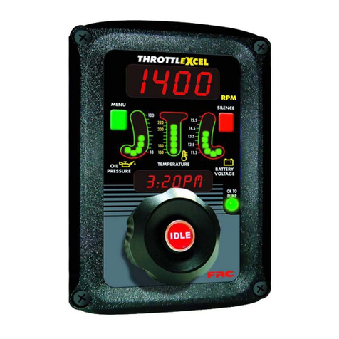
FRC ThrottleXcel ELA100 User manual

ELA100 Rev0604
1
FIRE RESEARCH CORPORATION
www.fireresearch.com
26 Southern Blvd., Nesconset, NY11767
TEL ( 631 ) 724-8888 FAX ( 631 ) 360-9727 TOLL FREE 1-800-645-0074
ENGINE THROTTLE
AND MONITORING DISPLAY
MODEL: ELA100

ELA100 Rev0604
2
CONTENTS
Table of Contents
CONTENTS ............................................................................................................... 2
INTRODUCTION ...................................................................................................... 4
Overview ............................................................................................................... 4
Features ................................................................................................................. 4
Specifications ........................................................................................................ 5
GENERAL DESCRIPTION....................................................................................... 6
Components........................................................................................................... 6
Controls and Indicators ......................................................................................... 8
INSTALLATION......................................................................................................10
Install Control Module ........................................................................................ 10
Install Sensors ..................................................................................................... 10
Install Buzzer.......................................................................................................10
OPERATION ............................................................................................................ 12
Display Stored Data............................................................................................14
High Idle............................................................................................................. 15
PROGRAMMING.................................................................................................... 16
Program Code Descriptions ................................................................................17
WIRING ...................................................................................................................18
Connectors and Cables........................................................................................18
Cummins Harness Connections ..........................................................................20
Detroit Diesel (Series 50 and 60) Harness Connections..................................... 22
Navistar and Detroit Diesel (Series 40) Harness Connections ...........................23
Caterpillar Harness Connections......................................................................... 24
Ford Harness Connections ..................................................................................27
Mack Harness Connections................................................................................. 32
Scania Harness Connections ............................................................................... 33
GMAC Harness Connections..............................................................................34
Mercedes Harness Connections ..........................................................................36

ELA100 Rev0604
3
List of Tables
Table 1. Error Codes................................................................................................13
Table 2. Fault Warning Codes .................................................................................13
List of Figures
Figure 1. Controls and Indicators.............................................................................. 9
Figure 2. Control Module Mounting Dimensions................................................... 11
Figure 3. 12-Pin Connector Wiring......................................................................... 18
Figure 4. 8-Pin Connector Wiring ........................................................................... 19
Figure 5. Cummins ELA101 Wiring ....................................................................... 20
Figure 6. Detroit Diesel (Series 50 and 60) ELA102 Wiring ................................. 22
Figure 7. Navistar ELA104 Wiring (and Detroit Diesel Series 40 ELA102B) ...... 23
Figure 8. Caterpillar ELA105 Wiring ..................................................................... 24
Figure 9. Ford 7.3L ELA106-A Wiring................................................................... 27
Figure 10. Ford 6.0L ELA106-B Wiring................................................................. 28
Figure 11. Mack ELA107 Wiring............................................................................32
Figure 12. Scania ELA108 Wiring.......................................................................... 33
Figure 13. GMAC ELA109 Wiring.........................................................................34
Figure 14. Mercedes ELA110 Wiring ..................................................................... 36
Figure 15. Mercedes Euro ELA110B Wiring.......................................................... 37

ELA100 Rev0604
4
INTRODUCTION
Overview
The ThrottleXcel is an all-in-one instrument panel that integrates a traditional
style remote hand throttle with engine monitoring and display. It offers complete
remote display and engine control (as a remote throttle, the ThrottleXcel is not an
engine governor) in a single compact unit.
The panel has a 4-digit LED display for engine RPM, three LED bar graphs that
provide a constant display of the engine oil pressure, engine coolant temperature, and
battery voltage. It has a message display that shows the time and date during normal
operations and fault warning alarms as they occur. When selected by the operator it
will show monitored information, stored data, and program options.
The ThrottleXcel panel has a built-in FRC infinityPRO remote engine throttle.
This hand throttle uses optical technology with an Infrared Encoder (IRE) to detect
the direction and speed of the control knob as it is rotated. There is no potentiometer,
electromechanical switch, or mechanical stop. The electrical signal from the encoder
is interpreted by a microprocessor and the engine RPM control signal is adjusted.
This will cause the engine RPM to increase or decrease proportionally to how fast the
control knob is rotated. The engine RPM control signal will be set at idle when power
is applied to the ThrottleXcel regardless of the control knob position.
Engine information is input via the J1939 databus and/or installed sensors.
Features
Always Starts From Idle RPM
Large RPM Display
Three Bi-Color LED Bar Graphs
Message Display
Visual Warning Alarms
Field Programmable Alarm Levels
Records Date and Time of Warning Alarm Occurrences
Records Accumulated Hours
Interlock Signal Recognition
Remote Hand Throttle with Idle Button and No Mechanical Stops
High Idle Function
Audible Warning Alarms (Optional)
Interconnected Multiple Panels (Optional)

ELA100 Rev0604
5
Specifications
Display Module
Supply Power: 9 - 30 VDC
Supply Current: 0.5 Amps
Dimensions: 4.5" Wide by 6.75" High
LED Bar Graphs
Oil Pressure: 10 - 100 PSI (10 PSI Increments)
Temperature (Engine Coolant): 130 - 220 °F (10° Increments)
Battery Voltage: 11.5 - 16 Volts (0.5 Volt Increments)
Sensors
Engine Coolant Temperature: 100 - 250 °F, 1/2" - 14 NPT
Engine Oil Pressure: 0 - 100 PSI, 1/8" NPTF
Transmission Temperature: 140 - 320 °F, 1/8" NPTF

ELA100 Rev0604
6
GENERAL DESCRIPTION
The ThrottleXcel all-in-one instrument panel with a remote hand throttle is
compatible with the following engines:
ELA101 Cummins IS Series
ELA102 Detroit Diesel
ELA104 Navistar
ELA105 Caterpillar
ELA106* Ford
ELA107 Mack
ELA108 Scania
ELA109* GMAC
ELA110 Mercedes
*Note: An adapter and cable assembly replaces the basic 8-pin cable when
connecting the ThrottleXcel to a Ford 6.0 or GMAC engine.
The ThrottleXcel is a remote display and has a remote throttle for engine RPM
control, it is not an engine governor.
Components
The information available on the J1939 databus varies depending on the particular
engine type. The sensors (if any) that need to be installed will also vary depending on
the engine.
The ThrottleXcel consist of the following components:
Contol Module
Engine Coolant Temperature Sensor (As Necessary)
Engine Oil Pressure Sensor (As Necessary)
Transmission Temperature Sensor (Optional)
Cables
Contol Module
The control module is waterproof and takes up 4 5/8 by 6 3/4 inches of panel
space.All controls and indicators are located on the front of the control module. (Refer
to Controls and Indicators.)

ELA100 Rev0604
7
Engine Coolant Temperature Sensor
The engine coolant temperature sensor is installed as necessary.
Oil Pressure Sensor
The oil pressure sensor is installed as necessary.
Transmission Temperature Sensor (Optional)
The optional transmission fluid temperature sensor is installed as necessary.
Cables
There are two cables that connect to the control module. The 8-pin connector is
for the remote throttle interface, the 12-pin connector is for the monitoring and display
interface.

ELA100 Rev0604
8
Controls and Indicators
All controls and indicators are located on the front of the control module. (Refer
to Figure 1.) See Operation and Programming Sections for more information.
RPM Display
Shows the current engine RPM in bright red digits during normal operations. It is
used to show error codes, fault warnings, stored data, and program features.
SILENCE Button
Pressed to suppress audio alarms. Used when accessing stored data and program
features. See the Programming Section for more information.
BATTERY VOLTAGE LED Display
Shows the real time battery voltage. The LEDs will be green when the voltage is
within normal limits and red when it is not.
OK TO PUMP LED
This LED will be on when the required interlock conditions are met and the throttle
is ready to begin pump operations.
Remote Hand Throttle Control Knob
When rotated changes the engine RPM. The engine RPM will increase or decrease
proportionally to the speed and direction the control knob is rotated.
IDLE Button
When pressed immediately sets the engine RPM to idle. This button can be used
in an emergency or for normal shut down after operations.
Message Display
The message display shows the time and date during normal operations and
warning alarms as they occur. It is used when accessing stored data and program
features.
TEMPERATURE LED Display
Shows real time engine coolant temperature. The LEDs will be green when the
temperature is within normal limits and red when it is not.
OIL PRESSURE LED Display
Shows real time engine oil pressure. The LEDs will be green when the pressure is
within normal limits and red when it is not.
MENU Button
Used when accessing stored data and program features.

ELA100 Rev0604
9
Figure 1. Controls and Indicators
RPM
Display
Message
Display
OIL PRESSURE
LED Display
TEMPERATURE
LED Display
SILENCE
Button
MENU
Button
BATTERY
VOLTAGE
LED Display
Remote Hand
Throttle
Control Knob
IDLE
Button
OK TO PUMP
LED

ELA100 Rev0604
10
INSTALLATION
Install Control Module
1. Measure and mark mounting location for control module panel cutout and
mounting screw holes. Make sure there is clearance behind the panel for the
module and cables before cutting holes. Refer to Figure 2 for layout and
dimensions.
2. Cut out a 3 7/16 by 5 11/16 inch hole.
3. Drill four holes, clearance or tapped, for 10-32 mounting screws.
4. Place control module in position and secure with screws.
5. Connect cables at rear of the control module. (Refer to Wiring section.)
Install Sensors
For most electronic engines, the ThrottleXcel receives engine RPM, oil pressure,
and coolant temperature data over the J1939 databus from the engine ECM. Some
enginesdo not broadcast thisdata over thedatabus and sensorsmay need tobe installed.
The sensors are wired to the 12-pin connector at the rear of the control module.
Refer to the Wiring section (Figure 3) for pinout and wire color information.
An input is provided for an optional transmission temperature sensor.
Install Buzzer
Pin 6 on the 12-pin connector at the rear of the control module is provided to
connect an optional buzzer. Connect the ground side of the buzzer to pin 6. (Maximum
current through pin 6 is 300 mA.) Refer to the Wiring section (Figure 3).

ELA100 Rev0604
11
Figure 2. Control Module Mounting Dimensions
Mounting holes are
clearance or tapped
for 10-32 screws.
1 3/4" 4 5/8"
6 3/4"
3 7/16"
5 11/16"
Panel
Cutout 5 3/4"
4"
Maximum
Radius 1/2"

ELA100 Rev0604
12
OPERATION
Onpower-upthe ThrottleXcelwill bein normaloperating mode.The RPM display
will show engine RPM, the three LED bar graphs will be green indicating readings
within normal ranges, and the message display will alternate between showing the
date and time.
If a monitored function is not within normal parameters the displays will flash,
the RPM display will show an error code and a description will show in the message
display. (Refer to Table 1. Error Codes.) If one of the inputs displayed by the LED bar
graphs is not within normal range the LEDs will be red.
If a fault occurs the RPM display will show the fault code and a description will
show in the message display. (Refer to Table 2. Fault Warning Codes.)
When all necessary throttle enables are active and the interlock circuit is complete
the OK TO PUMP LED will light and the remote throttle will be controlling engine
RPM. The engine RPM control signal will be set at idle regardless of the control knob
position.
Remote Hand Throttle
The remote hand throttle is used to adjust engine RPM. The ThrottleXcel will
sense how fast and in what direction the control knob is rotated and send a signal to
the ECM to increase or decrease the engine RPM proportionally.
If the control knob is rotated quickly; the RPM will change quickly.
If the control knob is rotated slowly; the RPM will change slowly.
• Rotate the control knob clockwise to increase engine RPM.
• Rotate the control knob counterclockwise to decrease engine RPM.
• Press the red IDLE button to immediately return the engine to idle.
SILENCE Button
During normal operations the silence button is used to suppress an optional audio
alarm.
MENU Button
During normal operations the menu button is used to access the accumulated
hours mode.

ELA100 Rev0604
13
Table 1. Error Codes
Table 2. Fault Warning Codes
RPM Message
Display Display Description
F01 N/A
F02 N/A
F03 HI RPM High RPM
F04 N/A
F05 N/A
F06 Tran Temp High transmission temperature
F07 Low Batt Low battery voltage
F08 Hi Batt High battery voltage
F09 Low Oil Low engine oil pressure
F10 Eng Temp High engine coolant temperature
RPM Message
Display Display Probable Cause
E01 NO DATA >Datalink cable not connected / connected to wrong port
>Broken wire / bad connector contact on datalink cable
E02 N/A N/A
E03 NO RPM >Datalink cable not connected / connected to wrong port
>Engine not running / ignition key on
>Broken wire / bad connector contact on alternator cable
E04 N/A N/A
E05 N/A N/A
E06 N/A N/A
E07 N/A N/A
E08 TRANS T’ >Sensor cable not connected
>Broken wire / bad connector contact on sensor cable
>Defective temperature sensor
E09 ENG OIL’ >Sensor cable not connected
>Broken wire / bad connector contact on sensor cable
>Defective pressure sensor
E10 ENG T’ >Sensor cable not connected
>Broken wire / bad connector contact on sensor cable
>Defective temperature sensor

ELA100 Rev0604
14
Display Stored Data
Both the RPM and the message displays are used to show stored data.
Accumulated Hours
Accumulated hours are stored in memory for engine operation, pump operation,
last incident, and current incident. The menu button allows the operator to gain access
to this stored data. When in the accumulated hours mode the RPM display will show
the hours. The message display will show the following:
Pump Operating Hours
Engine Operating Hours
Last Incident Hours
Current Incident Hours
The accumulated hours mode is a display only mode and no changes can be made
to the data.
Press the MENU button to enter the accumulated hours mode.
Stored accumulated hours will be displayed.
The RPM display will show the number of hours.
The message display will show what the hours are for.
Press the MENU button to show the next stored hours.
Each time the MENU button is pressed the displays will change to show the
next block of stored accumulated hours.
Press and hold the MENU button for 5 seconds.
The displays will continuously cycle to show all of the stored accumulated
hours.
Press the SILENCE button to exit the accumulated hours mode.
Fault Warnings
Each time a fault occurs, the type of fault, date, and time are stored in memory.
The memory will hold the last five (5) fault occurrences to be displayed at a later time.
Refer to the Programming section for details on retrieving fault warnings.
Maximum Engine RPM
The maximum RPM that the engine reaches will be stored in the memory to be
displayed at a later time. Refer to the Programming section for details on retrieving
the maximum engine RPM.

ELA100 Rev0604
15
High Idle
The ThrottleXcel programming includes a high idle function. To activate the
high idle provide 12 VDC to pin 7 (High Idle Active Input) and pin 8 (High Idle
Throttle Enable Input) of the 12-pin connector. It is recommend to connect pin 7 to
the high idle switch (not provided) and pin 8 to the safety interlock circuit.
The high idle is set at about 1000 RPM at the factory. (This value will vary
depending on the specific engine the ThrottleXcel is programmed for.)
Set High Idle
Note: The high idle is active when +12 VDC is at pins 7 and pin 8 of the 12-
pin connector. (Refer to the Wiring section.)
1. Active the high idle.
2. Press and hold the IDLE button for 10 seconds.
3. Keep pressing the IDLE button and rotate the control knob to the desired
RPM.
4. Release the IDLE button.

ELA100 Rev0604
16
PROGRAMMING
To gain access to the program features a four digit program code must be entered.
Review the Program Code Descriptions for the proper four digit code.
Both the MENU and SILENCE buttons are used to enter a program code. The
RPM display is used to show the codes.
Enter Program Code
Note: There is a time out feature that will return the program to normal
operation in three seconds if input is not detected at the buttons.
1. Press the SILENCE button and hold it for 3 seconds until the RPM display
shows four dashes. The program is ready for a three digit program code to be
input.
2. Press the MENU button. The RPM display will show the number 1000. Each
time the MENUbutton is pressed the first digit will scroll up by 1. Set the first
digit to the number desired.
3. Press the SILENCE button. Each time the SILENCE button is pressed the
second digit will scroll up by 1. Set the second digit to the number desired.
4. Press the MENU button. Each time the MENU button is pressed the third
digit will scroll up by 1. Set the third digit to the number desired.
5. Press the SILENCE button. Each time the SILENCE button is pressed the
fourth digit will scroll up by 1. Set the fourth digit to the number desired.
6. Wait a few seconds:
If a valid four digit program code is entered the display will change to show a
program value or an option.
If an invalid code is entered the display will show WRONG CODE.

ELA100 Rev0604
17
Program Code Descriptions
When a valid four digit program code has been entered, stored data or program
options will show in the displays. (Refer to Programming.)
The MENU and SILENCE buttons are used to change the data. The SILENCE
button will select the digit that is to be changed. The MENU button will change the
digit or change the option choice.
Data Display Codes 1000
1110 - Fault Warnings
This code will display the last five (5) fault warnings that have occurred. The
RPM display will show a fault code and the message display will alternate between
showing the date and time that the fault occurred. Refer to Table 2. Fault Warnings
1120 - Maximum Engine RPM
This code will display the maximum RPM that the engine has attained.
1130 - Software Revision
This code will display the current software revision code.
Parameter Settings Codes 2000
2110 - Clock
This code will allow the clock display to be changed.
2120 - Date
This code will allow the date display to be changed.
2130 - Clear Fault Warnings
This code will allow the stored fault warnings to be cleared from memory. It will
clear the history of all five (5) fault warnings. Select YES or no.
2140 - RPM Calibration
This code will allow the digits in the RPM display to be adjusted to match a
tachometer. This is for engines that do not receive RPM data over the datalink and
have the yellow RPM signal wire (pin 12 on the 12-pin connector) connected to an
RPM source.
Exit Program Code Mode
Press the SILENCE button first then the MENU button and hold them both for 3
seconds to exit the program code mode and return to normal operation.

ELA100 Rev0604
18
Notes:
- Not all wires are used for all engines.
- For Ford 6.0L engines the yellow RPM signal wire, pin 12, should be connected
to the Clean Tachometer Output [green/white wire, circuit #76].
WIRING
The following figures include the schematics, wiring diagrams, block diagrams,
and cables for the ThrottleXcel.
Connectors and Cables
Figure 3. 12-Pin Connector Wiring
12-Pin
Deutsch
Connector
Butt
Connectors
12 Pin Connector/Cable
Pin Wire Color Description
1NC -
2NC -
3NC -
4 BLU Engine Oil Press. Sensor Signal
5 ORG Engine Temp. Sensor Signal
6 BRN Buzzer Ground (300mA)
7 VIO High Idle Active Input (+12 VDC)
8 WHT High Idle Throttle Enable Input (+12 VDC)
9 BLK CAN J1939 (–)
10 RED CAN J1939 (+)
11 GRN Transmission Temp. Sensor Signal
12 YEL RPM Signal
NC
NC
NC
BLU
ORG
BRN
VIO
WHT
BLK
RED
GRN
YEL
12-Pin Cable
12
12
12
12
12
1
1
1
1
1

ELA100 Rev0604
19
Figure 4. 8-Pin Connector Wiring
8 Pin Connector/Cable
Pin Wire Color Description
1 Red Supply Voltage (9 to 30 VDC)
2 Black Ground
3 Orange +5 VDC Reference From ECM
4 White Throttle Signal To ECM
5 Green Signal Return From ECM
6 Yellow Interlock Input (12 or 24 VDC)
7 Blue Throttle Enable Signal Output
8 Brown Foot Pedal Signal Input
8-Pin
Deutsch
Connector
Note: Not all wires are used for all engines. Refer to the
engine specific wiring diagram for interface connections.
Butt
Connectors
Note: An adapter and cable assembly replaces the basic 8-pin
cable when connecting the ThrottleXcel to a Ford 6.0 or
GMAC engine. Refer to the engine specific wiring diagram.
Control
Module Rear
View
8-Pin
Connector
Pin 1 12-Pin
Connector
Pin 1
8-Pin Cable
RED
BLK
ORG
WHT
GRN
YEL
BLU
BRN
12
12
12
12
1
1
1
1

ELA100 Rev0604
20
Cummins Harness Connections
Interface Information
The ECM RemoteAccelerator (Throttle) Option hasto beset to ON.The diagnostic
tool cannot be used to do this, an Insight service tool must be used. Refer to an
authorized dealer to program this option.
ISB, ISC, and ISL Engine Interface
Figure 5. Cummins ELA101 Wiring
(Sheet 1 of 2)
+12 (24)
VDC
Ignition Key
GND
+12 (24) VDC
Pump Engaged
Interlock
8-Pin Cable
(Refer to
Figure 3 )
RED
BLK
ORG
WHT
GRN
YEL
BLU
BRN
12
12
12
12
12
ECM 50-Pin
B Connector
10
REMOTE THROTTLE RETURN (SRTN B)
REMOTE THROTTLE PEDAL POSITION INPUT
REMOTE THROTTLE +5VDC (VSENSOR B)
20
REMOTE THROTTLE ON/OFF INPUT
9
45
6
SELECT THROTTLE CONTROL SWITCH
ECM 50-Pin
J2 Connector
21
ECM Return (Sensor)
Remote Accelerator Position
Sensor Supply
32
Remote Accelerator On/Off Switch
26
03
14
Max Operating Speed/Governor Type Switch
ISB02/ISC03/
ISL03-CM850
Model
Engines
Other manuals for ThrottleXcel ELA100
1
This manual suits for next models
9
Table of contents
Other FRC Measuring Instrument manuals

FRC
FRC DFA400 User manual

FRC
FRC ThrottleXcel ELA100 User manual

FRC
FRC Insight Ultimate Series User manual

FRC
FRC Air Sentinel AMA200 User manual

FRC
FRC SeatMonitor SBA1GD User manual

FRC
FRC DFA400 User manual

FRC
FRC FPA400 User manual

FRC
FRC InView 360 HD AVM User manual

FRC
FRC Insight Series User manual

FRC
FRC FPA400 User manual