18
Dark Blue Wire:
Connection Required
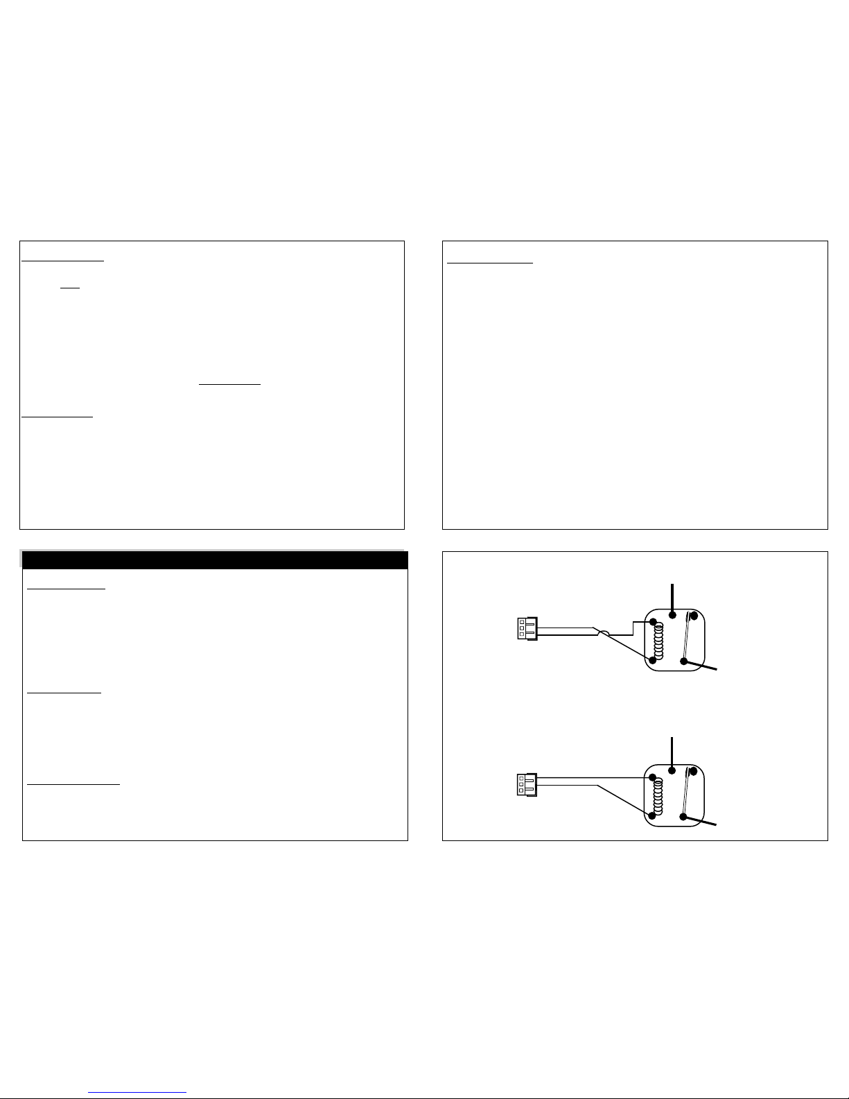
The hood pin switch must be installed. It prevents operation of the RS unit
if the hood is open.
Connect the Dark Blue wire to the hood pin switch. Carefully route the Dark Blue
wire through the firewall, using an added or existing grommet. Avoid any hot or
moving parts. Mount the switch so that it is open (pin down) when the hood is shut
and closed (pin up) when the hood is open.
If there is an existing hood pin switch for an alarm system, you may use it for
the Dark Blue wire connection; diode-isolation is recommended.
Insteadof using a pin switch to monitor the hood's open orshut status, anOmega
AU-46 Mercury Tilt Switch may used. Connect one of the AU-46's wires to Nega-
tive Chassis Ground and connect the remaining wire to the Dark Blue wire.
Hood
Pin
Switch
To Existing Alarm Dark Blue Wire
Optional Parts Needed:
Two IN4002 Diodes
Diagram #8
19
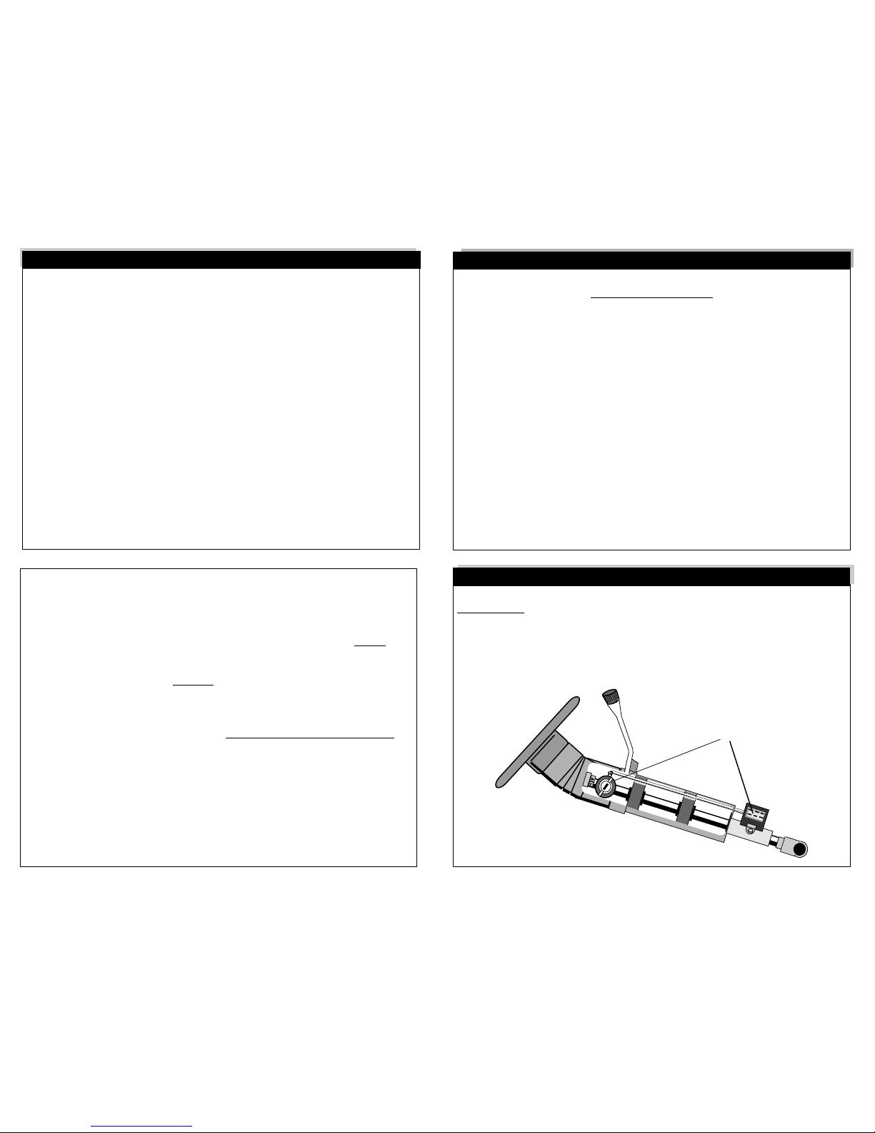
Remote Start Override Mode:
The RS unit can be placed into an "Override" mode which will prevent it from
starting the vehicle. This mode is for situations when it is not convenient or safe
for the Remote Start feature to be operable. For example during extended stop-
overs for vehicle servicing, maintenance, valet parking, washing, etc.
Connect the Dark Blue wire to one of the included toggle switch's two wires. Con-
nect the toggle switch's remaining wire to ground.
Hood
Pin
Switch
Dark Blue Wire
Diagram #9
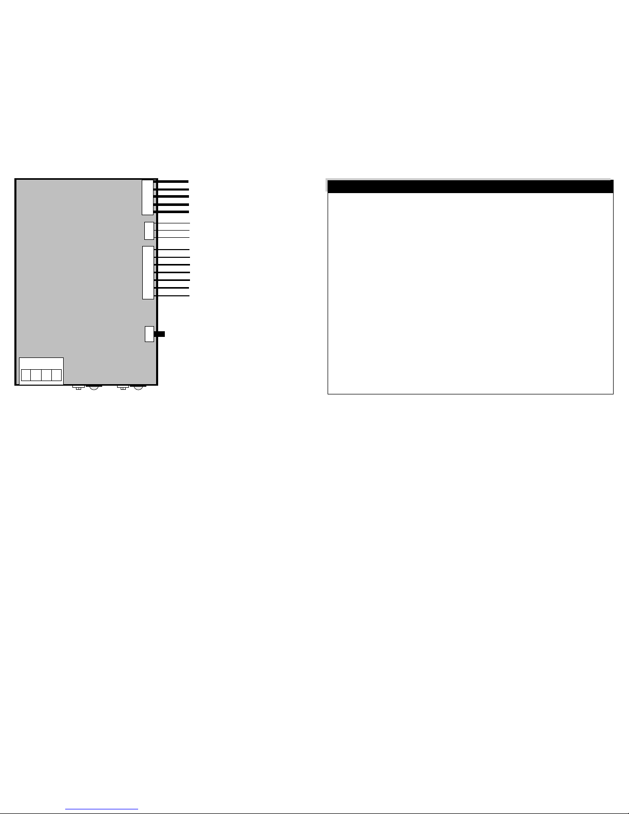
Ground
Control
Module
20
Yellow/Black Wire:
Connection
Required
The Yellow/Black wire must be connected. It is part a critical safety feature
which disables the RS unit whenever the brake pedal is pressed.
Connect the Yellow/Black wire to the brake switch wire which shows 12 Volts
when the brake pedal is pressed. The brake switch is typically located above the
brake pedal, and usually mounted to the brake pedal support bracket. Always
make this connection in a fashion ensuring its long-term reliability; soldering is
highlyrecommended. UponcompletingtheYellow/Blackwire's connection, thor-
oughly test the operation of this circuit.
Pink Wire:
Connection If Desired
The Pink wire activates the RS Unit. If the Pink wire receives a Negative
pulse, the RS unit will start the vehicle's engine, provided that all safety circuits
are in the proper status. After the engine has been started by remote control,
another Negative pulse on the Pink wire will turn the RS unit off, stopping the
engine.
Connect the Pink wire to an available auxiliary output of an existing Remote
Security or Keyless Entry System.
21
Orange/Black Wire:
Connection Required
The Orange/Black wire is the engine detect wire. The RS unit utilizes three
different methods of monitoring the vehicle during the remote starting process.
Considerallmethodsbeforedecidingwhichoneto use. Normally the Smart Start
method is used.
1) Vacuum Switch Sensing:
This method uses a Vacuum switch to verify that the vehicle' engine is running.
The Orange/Black wire connects to one of the Vacuum switch's wires, the other
wire is connected to chassis Ground. Connect the Vacuum switch using a "T"
connector to a vacuum hose on the engine's intake manifold.
1) Position the 3-way selector switch for Vacuum switch operation (right position).
2) Locate the Smart Start & Tach Sense adjustment screws and LED indicators.
3) Turn BOTH adjustment screws completely counterclockwise.
Note: Using a multimeter set to Ohms, measure the resistance of the Vacuum
switch. The switch should read Zero resistance when the engine is "Off" and
read Maximum resistance (open circuit) when the engine is running. If this is not
the case, relocate the vacuum connection.