31
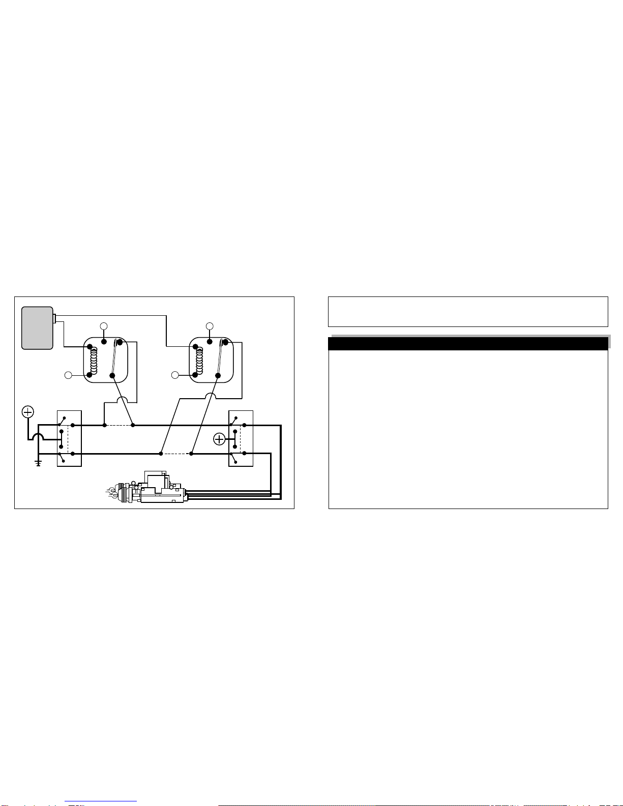
5 Wire Reversing Polarity Systems
This power doorlock system differs from the negative and positive pulse systems in
that there is no doorlock control unit or relays. In this type of system, the switches
themselvessupplythe positive voltagedirectly to thedoorlock actuators, and,more
importantly, provide the return ground path. It is important to note that the lock and
unlockwiresinthissystem
actuallyrestatchassisground.
Thismeansthatboththe
lock and unlock wires must be "opened", or cut, to make the proper connections.
Examine the wires on the back of the switch. (Normally 5 wires will be found)
1) One wire will show +12 Volts, regardless of the switch's position.
2) Two wires will be grounded regardless of the switch's position.
3) One wire will show +12 Volts only when the switch is pushed to "Lock".
4) One wire will show +12 Volts only when the switch is pushed to "Unlock".
-Whenthelock/unlockwiresarefound,theymustbecutoneatatime.Ifthecorrect
wiresarecut the door lockingsystemshould not operate fromtheprimary switch.
-Noticethatinthediagram the driver's switchistheprimary or “Master” switch (in
some vehicles, the primary switch is on the passenger's side). The half of the cut
wireswhichcomefromthisprimaryswitcharereferredtoasthe"Switch"side.The
halfofthecutwireswhichgotothesecondaryswitcharereferredtoasthe"Motor"
side even though the cut is made between the switches.
10
IMPORTANT!
After reading this manual, start the installation by affixing the
WARNING DECAL to a visible area in the engine compartment!
InstallationConsiderations: Thisentirebookletshouldbereadbefore starting
the installation. An understanding of which control module wires are to be used
and their functions is essential. Installations will vary from car to car, as some
control module wires are required, while others are optional. Before starting the
installation, it should be determined which control module wires will be used.
Most installers will list these wires, then "map out" the installation by locating and
notingthe target wires in the vehicle. This will also determine the best locationfor
the RS control module, which is mounted upon completion of the installation.
This Remote Start Unit duplicates the actions that occur within the ignition
switch when you use your key to start the engine. Because of this, most of the
mainwiring harness connections will be made at the ignition switch harness. The
ignition switch wires usually are high amperage circuits, which means that high
reliabilityconnectionsmustbemade-solderingofallconnectionsisrecommended.
Caution!
Avoid the Airbag circuit!
Especially avoid any harness or wires en-
cased in Yellow or Red tubing or sleeves. Do not use a standard test light, as it
can deploy an airbag or damage on-board computers and sensors.
Installation Instructions