39
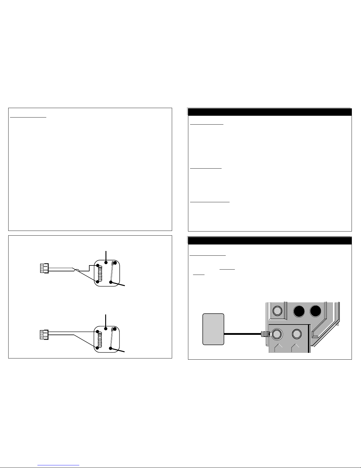
4 3 2 1
Jumpers
Trap Door
Smart Start
Tuner & LED Tach Sense
Tuner & LED
Antenna Port
5 Wire Connector
3-Wire Blue Connector
10-Wire Connector
Engine Detect Selector Switch
Program Button
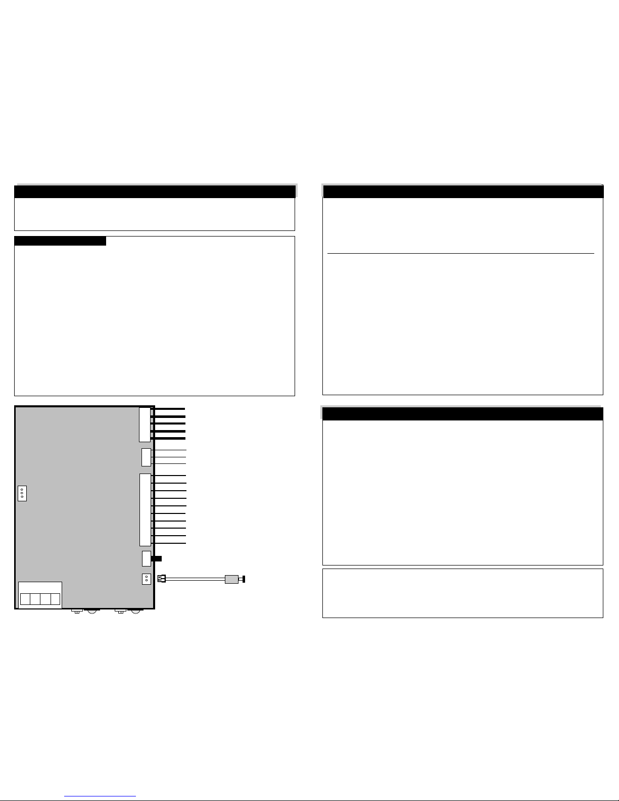
Green = Starter
Yellow = Accessory
Red = +12 Volts
Red = +12 Volts
Blue = Ignition 1
Yellow = - Accessory 2 Output
Red = Constant +12 Volts Output
Blue = - Ignition 2 Output
Black = Chassis Ground
White = + Parking Lights Output
Dark Blue = - Hood Pin Switch Input
Yellow/Black = + Brake Pedal Input
Pink = - Activation Input
Gray = - Auxiliary Output
Light Blue = - Unlock Output
Green = - Lock Output
Orange/Black = Engine Detect Wire
Orange = Anti-Grind Output
Vacuum Sensing
Smart Start
Tach Sensing
40
ProductsmanufacturedandsoldbyOMEGARESEARCH&DEVELOPMENT,INC.(theCompany),are
warrantedtobefreefromdefectsinmaterialsandworkmanshipundernormaluse. Ifaproductsold
bytheCompanyprovestobedefective,theCompanywillrepairorreplaceitfreeofchargewithin
thefirstyearand thereafterallpartstoberepairedwillbefreewithonlyanominalchargeforOmega
ResearchandDevelopment,Inc.'slaborandreturnshipping,totheoriginalownerduringthelifetime
of the car in which it was originally installed.
All products for warranty repair must be sent postage prepaid to Omega Research &
Development,Inc.,P.O.Box508,Douglasville,Georgia30133,withbillofsaleorotherdatedproof
of purchase. This warranty is nontransferable and does not apply to any product damaged by
accident,physicalorelectricalmisuseorabuse,improperinstallation,alteration,anyusecontraryto
itsintendedfunction,unauthorizedservice,fire,flood,lightning,orotheractsofGod.
This warranty limits the Company's liability to the repair or replacement of the product. The
Companyshallnotberesponsibleforremovaland/orreinstallationcharges,damagetoortheftofthe
vehicleoritscontents,oranyincidentalorconsequentialdamagescausedbyanyfailureoralleged
failureoftheproducttofunctionproperly.UnderNoCircumstancesShouldThisWarranty,OrThe
ProductCoveredByIt,BeConstruedAsAGuaranteeOrInsurancePolicyAgainstLoss.TheCompany
neitherassumesnorauthorizesanypersonororganizationtomakeanyWarrantiesorassumeany
liabilityinconnectionwiththesale,installation,oruseofthisproduct.
ThisdevicecomplieswithF.C.CRulespart15.Operationissubjecttothefollowingtwoconditions:
(1)Thisdevicemaynotcauseharmfulinterferenceand,(2)Thisdevicemustacceptanyinterference
thatmaybereceived,includinginterferencethatmaycauseundesiredoperation.
The manufacturer is not responsible for any radio TV interference caused by unauthorized
modificationstothisequipment.Suchmodificationscould voidtheuser’s authoritytooperate the
equipment.
LIMITED LIFETIME WARRANTY
38
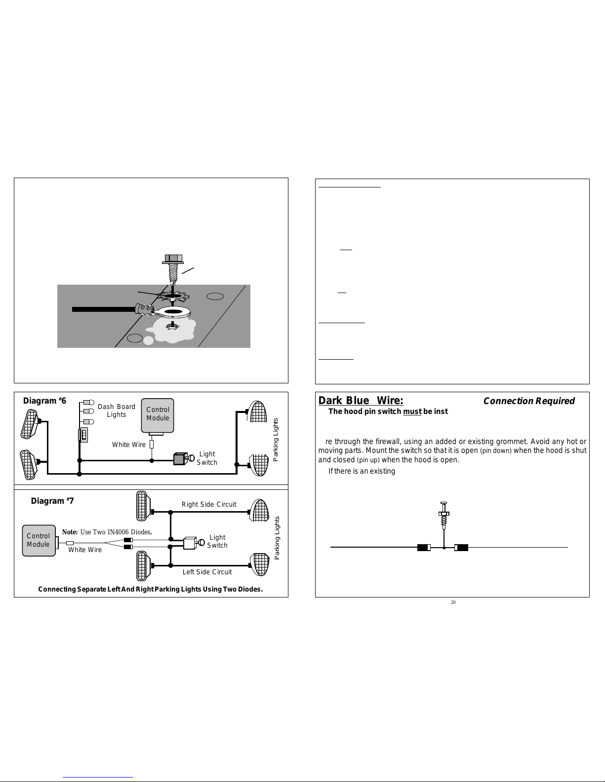
TheRSunithas four Jumper selectable programmablefeatures.Whenevera
jumper setting is changed, it is necessary to power down the RS unit for the
changeto be recognized. Jumper Jumper
Feature "In" Removed
Jumper#1 Tach Sense Sensitivity Normal High
Jumper#2 DoorUnlockPulse Single Double
Jumper#3 Engine RunningTime 15 Minutes 30 Minutes
Jumper#4 StarterMotorCrankingTime 1.2", 1.5", 2" 1", 1.5", 2"
FEATURES PROGRAMING
37
Upto4differenttransmittersmaybeprogrammedintotheRSunits'smemory.When
anewtransmittercode is programmed, all previouscodeswillbe deleted. If a third
or fourth transmitter is desired, all of the transmitters must be programmed.
1) Turn ignition "On".
2) Press & Release Program button 5 times.
- The parking lights will flash 5 times to confirm entry into programing mode.
3) Press any button of new Transmitter to be programed.
- The parking lights will flash to confirm that the Transmitter has been learned.
4) To program additional transmitters, Repeat step #3.
5) Turn ignition "Off".
Note 1: It is recommended that all four transmitter memory slots be filled. For
example:If you havetwo transmitters, program each one twice.
Note 2: The RS unit will automatically exit programing mode if 10 seconds elapse
withoutreceiving a signal fromthe transmitter(s).
TRANSMITTER PROGRAMING
To Program Transmitters: