RhinoBond Owner’s Manual Page 2
THE RHINOBOND SYSTEM WARRANTY
Guaranteed for 200,000 cycles of operation, or three years from date of purchase,
whichever comes first. During this period OMG, Inc., at its option, will repair or replace
any tool for the roofing contractor who originally purchased the tool. This will be done
free of charge, provided the tool is determined defective in materials or workmanship
upon examination by an Authorized RhinoBond System Service Technician.
This Warranty will be honored only if:
A. No evidence of abuse, misuse or failure to follow safety or operating instructions, or
improper modification of the tool, is present. (Read this Owner’s Manual for safe use
and proper operating instructions.)
B. When replacement is necessary, the first end-user returns the tool with transportation
prepaid, to the nearest Authorized RhinoBond System Service Technician with
purchase receipt or other positive proof of purchase.
C. Only genuine RhinoBond tool, fasteners, and plates are used in the application.
THE FOREGOING WARRANTY IS IN LIEU OF ALL OTHER WARRANTIES. ALL OTHER
WARRANTIES, WHETHER ORAL, WRITTEN, EXPRESS OR IMPLIED, INCLUDING BUT NOT
LIMITED TO THE IMPLIED WARRANTIES OF MERCHANTABILITY AND FITNESS FOR A
PARTICULAR PURPOSE SHALL NOT APPLY. THESE OTHER EXPRESS OR IMPLIED WARRANTIES
ARE SPECIFICALLY EXCLUDED. BUYER’S OR USER’S REMEDIES ARE SOLELY AND EXCLUSIVELY
AS STATED HEREIN. OMG, INC. SHALL IN NO EVENT BE LIABLE FOR INCIDENTAL,
CONSEQUENTIAL, INDIRECT OR SPECIAL DAMAGES RESULTING FROM FAILURE OF THIS
WARRANTY. IN NO EVENT, WHETHER AS A RESULT OF BREACH OF CONTRACT, WARRANTY,
TORT (INCLUDING NEGLIGENCE) OR OTHERWISE, SHALL OMG, INC.’S LIABILITY TO THE
BUYER OR USER OF THE TOOL OR ANY LOSS OR DAMAGE ARISING OUT OF THE BREACH
OF WARRANTY, CONTRACT OR TORT, EXCEED THE PURCHASE PRICE HEREIN. ANY CLAIM
OR LIABILITY SHALL IN ANY EVENT TERMINATE UPON THE EXPIRATION OF THE WARRANTY
PERIOD SPECIFIED ABOVE.
For RhinoBond Tool Service: 800.633.3800
ROOFTOP SAFETY
In addition to the safety instructions in this manual, OMG Roofing Products recommends that all roof top workers follow the safety
guidelines outlined in the OSHA booklet called "Protecting Roofing Workers" available at www.osha.gov/Publications/OSHA3755.pdf
and or EU-OSHA “Directive 92/57/EEC - Temporary or mobile construction sites,” as applicable.
INTRODUCING THE RHINOBOND®SYSTEM
Congratulations! The RhinoBond System is one of the industry’s most advanced fastening systems for
installing thermoplastic membrane roofing and, in Europe only, “approved” clean EPDM membrane*.
RhinoBond is a portable, easy-to-use, system that secures membrane to roofing substrates using micropro-
cessor-controlled induction welding.
Roofing installed this way has several benefits:
• Fewer Fasteners -- RhinoBond requires 25-50% fewer fasteners vs. mechanical attachment to meet FM
1-90 and Eurocode National wind uplift requirements.
• Zero Penetrations – The fasteners and plates used are all installed under the membrane, so with
RhinoBond there are no membrane penetrations or potential points of entry for moisture.
• Less Seaming – RhinoBond does not require any half-sheets, just full width membrane everywhere. This
can eliminate up to 30% of the seams when compared to a traditional mechanically attached system.
• Superior Wind Performance – The RhinoBond System has higher wind uplift resistance with fewer
fasteners and fewer seams when compared to mechanically attached roofs.
The RhinoBond system uses powerful induction technology to create a strong bond between the roofing
membrane and fastening plates. The technology that makes this possible, SINCH®Technology, is a compact
microprocessor-controlled electromagnetic induction bonding process. Today, this rugged technology is being
used to revolutionize industrial and consumer applications.
While RhinoBond is a safe, tested tool, we caution you to be sure that every member of your crew has a
thorough understanding of the RhinoBond System before attempting to use it. Read, understand and follow
all instructions.
Congratulations on your new purchase. We look forward to your feedback. Please send us your
comments and suggestions at any time.
RhinoBond Team
800.633.3800 | 413.789.0252 | www.rhinobond.com
*Clean EPDM Membrane -- currently there are a limited number of clean EPDM options available only in Europe and approved for
use with RhinoBond. Always verify membrane suitability and approvals with membrane supplier. RhinoBond is not suitable for use
with other EPDM membrane.
© Copyright 2020 OMG, Inc. All rights reserved.
RhinoBond®and SINCH Technology®are registered trademarks, OptiWeld™ is a trademark of OMG, Inc., a leading provider of
innovative fastening solutions and products for the construction industry.
PATENT NOTICE: U.S. Patent Nos. 6,710,314; 6,849,837; 7,399,949; 8,492,683; 8,933,379. Canadian Patent Nos. 2,458,353;
2,602,753. U.S. Patent Pending.
Contact OMG Roofing Products or your roofing membrane manufacturer for the most current list of approvals.
TABLE OF CONTENTS
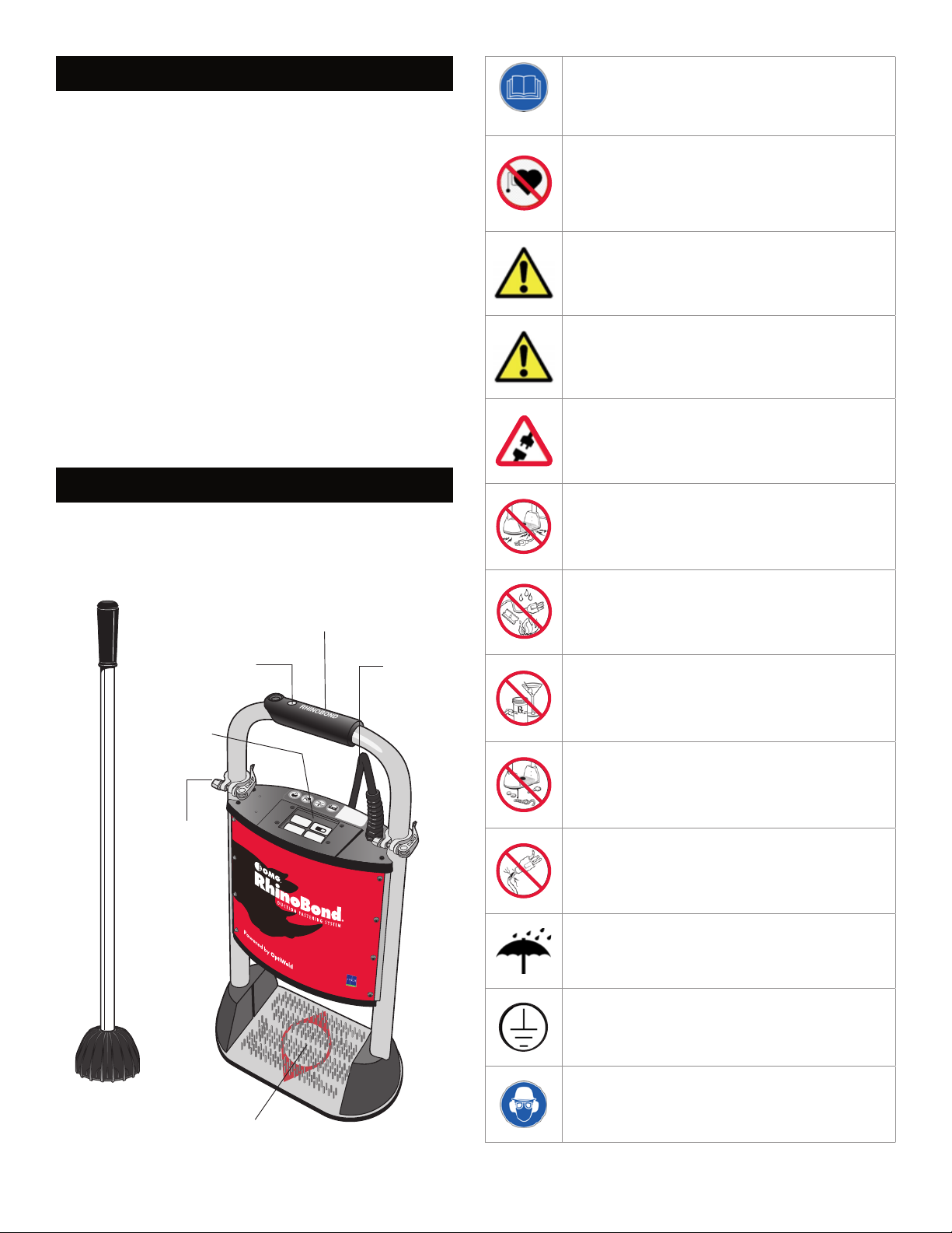
3 RhinoBond Tool & System Description
System Components
Power Requirements Chart
3 Safety Instructions
4 Operating Instructions
Power Requirements
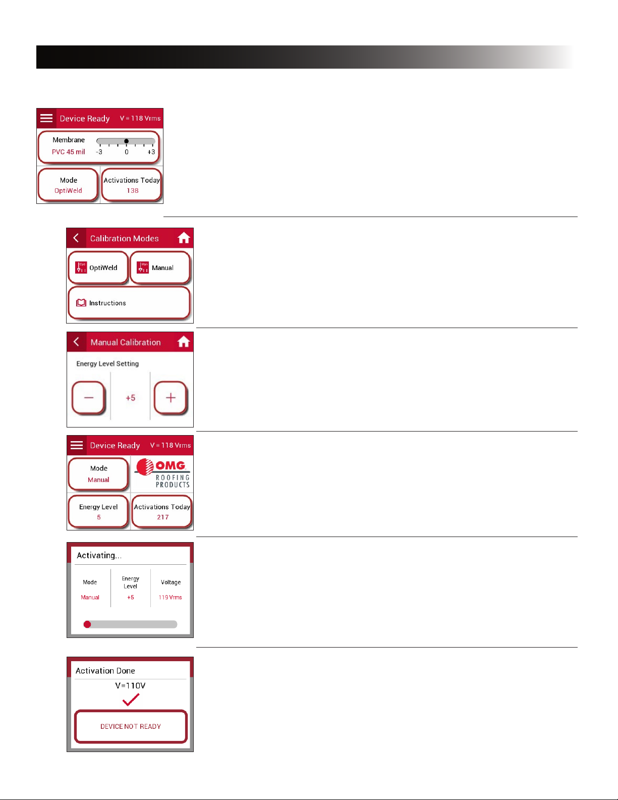
6 Tool Operation
Display Functions
Menu Options/Features
Error Messages
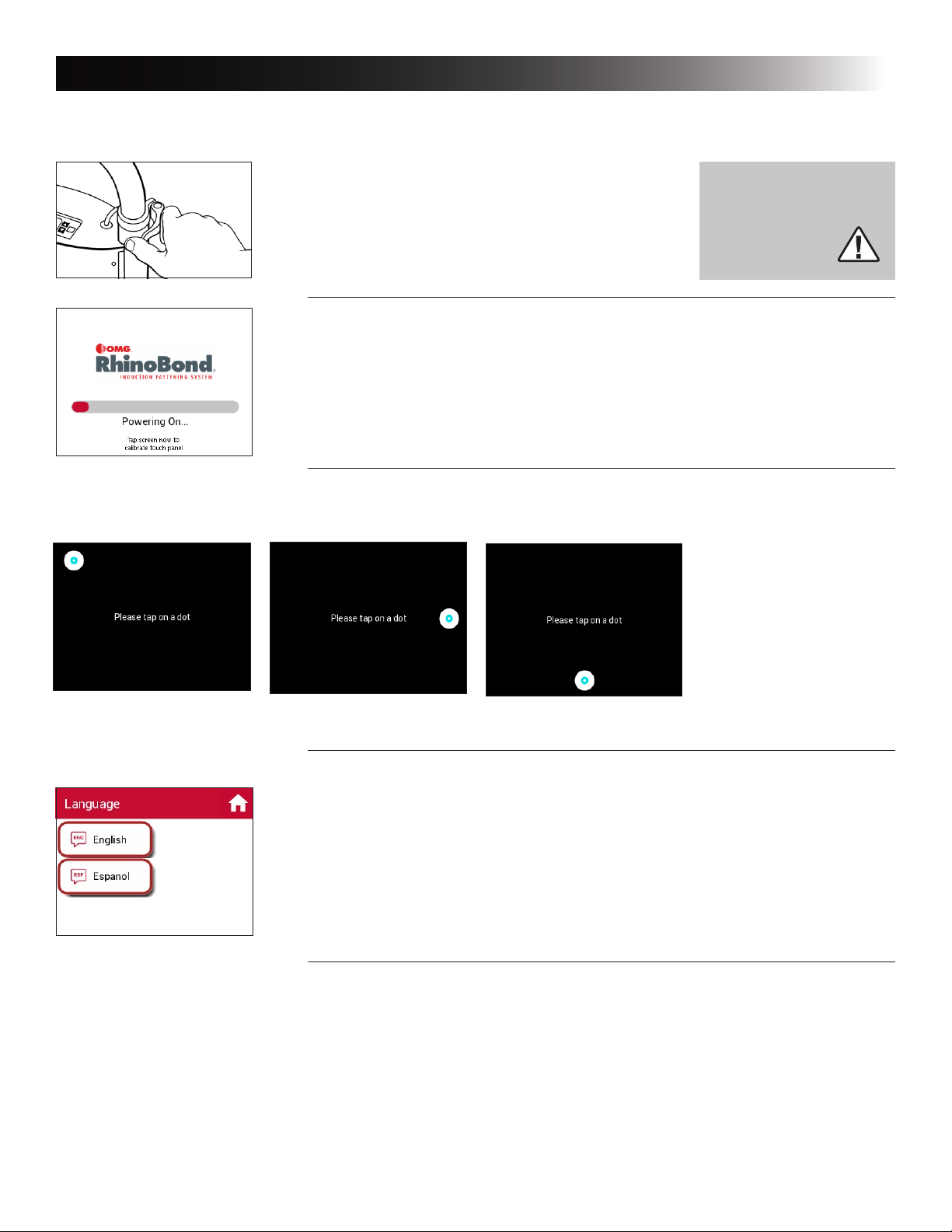
7 Automatic Calibration
8 Manual Calibration
10 Menu Settings
12 Troubleshooting
13 EC Declaration of Conformity