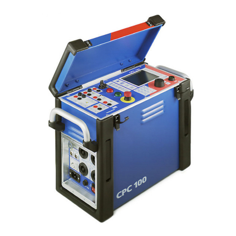
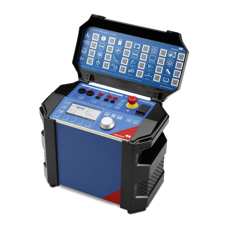
Omicron CPC 100 User manual

CPC
Getting Started

CPC Getting Started
2OMICRON
Manual version: ENU 1194 03 04
© OMICRON electronics GmbH 2020. All rights reserved.
This manual is a publication of OMICRON electronics GmbH.
All rights including translation reserved. Reproduction of any kind, for example, photocopying,
microfilming, optical character recognition and/or storage in electronic data processing systems,
requires the explicit consent of OMICRON. Reprinting, wholly or in part, is not permitted.
The product information, specifications, and technical data embodied in this manual represent the
technical status at the time of writing and are subject to change without prior notice.
We have done our best to ensure that the information given in this manual is useful, accurate and entirely
reliable. However, OMICRON does not assume responsibility for any inaccuracies which may be
present.
The user is responsible for every application that makes use of an OMICRON product.
OMICRON translates this manual from the source language English into a number of other languages.
Any translation of this manual is done for local requirements, and in the event of a dispute between the
English and a non-English version, the English version of this manual shall govern.

OMICRON 3
Safety instructions
1 Safety instructions
This document covers general safety instructions and information on the CPC 100 and CPC 80.
► For detailed information refer to the documents listed below and the user documentation for the
corresponding accessories.
• CPC 100 User Manual
• CPC 100 Reference Manual
• CPC 80 User Manual
1.1 Operator qualifications
Working on high-voltage assets can be extremely dangerous. Only authorized personnel who are
qualified and skilled in electrical engineering and trained by OMICRON are allowed to operate the
CPC 100 and its accessories. Before starting to work, clearly establish the responsibilities.
Personnel receiving training, instructions, directions, or education on the CPC must be under constant
supervision of an experienced operator while working with the equipment. The supervising operator
must be familiar with the equipment and the regulations on site.
1.2 Safety standards and rules
1.2.1 Safety standards
Testing with the CPC must comply with the internal safety instructions and additional safety-relevant
documents.
In addition, observe the following safety standards, if applicable:
• EN 50191 (VDE 0104) "Erection and Operation of Electrical Test Equipment"
• EN 50110-1 (VDE 0105 Part 100) "Operation of Electrical Installations"
• IEEE 510 "IEEE Recommended Practices for Safety in High-Voltage and High-Power Testing"
Moreover, observe all applicable regulations for accident prevention in the country and at the site of
operation.
Before operating the CPC and its accessories, read the safety instructions in this Getting Started
carefully. Do not turn on the CPC and do not operate the CPC without understanding the safety
information in this manual. If you do not understand some safety instructions, contact OMICRON before
proceeding.
► Observe all applicable regulations for accident prevention in the country and on the site of operation.
► If you do not understand the safety rules, contact OMICRON before proceeding.

CPC Getting Started
4OMICRON
1.2.2 Safety rules
Always observe the five safety rules:
► Disconnect completely.
► Secure against re-connection.
► Verify that the installation is dead.
► Carry out grounding and short-circuiting.
► Provide protection against adjacent live parts.
1.2.3 Safety accessories
OMICRON offers a range of accessories for added safety during the operation of our test systems. For
further information and specifications, refer to the corresponding Supplementary Sheet or contact
OMICRON Support (see "Support" on page 21).
1.3 Preparations on site
Prior to connecting a test object to the CPC, the following steps need to be carried out by an authorized
employee of the utility:
► Turn off and disconnect the high voltage from the test object.
► Protect yourself and your working environment against an accidental re-connection of high voltage
by other persons and circumstances.
► Verify that the installation is dead.
► Earth-connect and short-circuit the test object’s terminals using a grounding set.
► Protect yourself and your working environment with a suitable protection against other (possibly live)
circuits.
1.3.1 Static charges
Static charges on bushings or other apparatus such as transformer windings may be induced by test
potentials. While the voltage may not be significant enough to do any damage, it can be a source for
serious accidents due to falls caused by reflex action.
High static charges may also be encountered at the bushing capacitance taps if the covers are removed.
► Ground all test objects before handling.

OMICRON 5
Safety instructions
1.3.2 Grounding
Operating the device without PE and ground connection is life-threatening and not permitted.
► Only operate the CPC with a mains power supply connected to protective earth (PE).
► Make sure that both the PE connection of the power supply and the ground connector of the CPC
have a solid and low-impedance connection to the grounding system on site.
This also applies to all other test devices and accessories in the test setup.
► Make sure that the grounding clamp has a good electrical contact to the grounding system on site
and avoid connecting it to corroded or painted surfaces.
► Make sure that the grounding terminal connections of all grounded devices in use remain intact
during the whole measurement procedure, and are not accidentally disconnected.
► Only use ground and supply cables provided by OMICRON.
Connect the CPC grounding terminal to the grounding system on site.

CPC Getting Started
6OMICRON
1.3.3 Power supply
Operating the CPC without PE and ground connection is life-threatening and not permitted.
► Only operate the CPC with a mains power supply connected to protective earth (PE).
Power supply from grounded grids (TN/TT)
Before a measurement is started, the CPC automatically verifies the PE connection in grounded grids
(TN/TT).
► If this check fails, check the power cord and power supply.
If the error message persists, there is no intact connection to protective earth (PE).
This is life-threatening. In this case measurements are not permitted and cannot be performed.
Power supply from isolated grids (IT)
An IT grid is a grid structure where none of the active conductors are galvanically connected to ground.
In an IT grid, only the PE is connected to ground.
In IT grids, the check fails – even if there is a PE connection. This can be the case when the CPC is
powered by a generator. Since every operation mandates a PE connection for the operation of the CPC,
you need to manually verify this.
If the CPC is supplied by a generator, the equipotential ground or PE of the generator has to be grounded
properly.
► If this is not possible, measurements are not permitted and cannot be performed.
Additional information
Instead of supplying the CPC from phase-neutral (L1-N, A-N), it may also be supplied from phase-phase
(for example, L1-L2; A-B).
► Make sure that the voltage does not exceed 240V AC.
► Make sure that the power supply is fuse-protected (16 A automatic circuit breaker).
► Do not use an extension cable on a cable reel to prevent an overheating of the cord; run out the
extension cord.
► Keep extension cables as short as possible to prevent power loss.
If the power supply is ≤ 190 V AC, the CPC cannot provide the full output power at the 800A AC output.
The same applies when an external current booster is used.
► Therefore, in order to gain the full output power, provide a sufficient power supply
(190 V ... 240 V AC).
The Ext. Booster connector is always galvanically connected to mains and active.
This also applies when no external booster is selected, the green status light (0) is on, the outputs are
turned off, or the Emergency Stop button is pressed.
► Handle the Ext. Booster connector with extreme caution.
► Only use booster cables supplied by OMICRON.
► Do not use booster cables that are frayed or damaged in any way.
OMICRON 7
Safety instructions
1.4 Operating the measurement setup
► If the CPC 100 or any add-on device or accessory does not seem to function properly, do not use it
anymore. Please call the OMICRON hotline.
► If you have a cardiac pacemaker, do not use the CPC! If you have another type of electronic medical
implant, consult your doctor before operating the CPC. Make sure there is no person with an
electronic medical implant such as a cardiac pacemakerin the immediate vicinity.
► Before handling the CPC in any way, connect its grounding terminal to the grounding system on site.
► Make sure that the grounding clamp has a good electrical contact to the grounding system on site
and avoid connecting it to corroded or painted surfaces.
► Make sure that a test object’s terminals that are to be connected to the CPC 100 do not carry any
voltage potential. During a test, the only power source for a test
► Make sure that the ground terminal of the device under test is in good condition, clean and free of
oxidation.
► Protect others from accessing the high-voltage test area and accidentally touching live parts by
setting up a suitable barrier and, if applicable, warning lights.
► Do not enter the high-voltage test area if the red status light of the CPC is on since all outputs carry
dangerous voltage or current.
Figure 1-1: Separation of work area and high-voltage test area
► Do not open the CPC housing.
► Do not repair, modify, extend, or adapt the CPC or its accessories.
► Use only the original CPC accessories available from OMICRON.
►Use the CPC and its accessories only in a technically sound condition.
Make sure its use is in accordance with the regulations on site and the designated use described in
this document.
CPC
Device under test
Work area High-voltage test area

CPC Getting Started
8OMICRON
► Comply with the workflows described in this document. Avoid interruptions or distractions that could
affect safety.
► Do not insert objects (for example, screwdrivers, etc.) into any input/output socket.
► Use dry and clean cables and connectors.
► Do not connect any cable to the test object without a visible grounding of the test object.
► Do not remove any cables from CPC 100 or the test object during a test.
► Always lock connectors properly.
Before performing tests using high voltage, observe the following instructions:
► Do not operate the CPC under ambient conditions that exceed the temperature and humidity limits
specified in the respective user manual.
► Only use the CPC on dry, solid ground.
► Do not operate the CPC in the presence of explosives, gas or vapors.
► Unwind extension cables from their reel. Otherwise they will overheat.
► At their output sockets and especially in the cables connected to them, in operation the high-current
400A DC and 800A AC outputs generate a significant amount of heat (approx. 300 W/m at 800 A).
► After operation, wait for cables and clamps to cool down before touching them. If in doubt, wear
gloves.
► Never use the test cards Quick and Resistance to measure the resistance of windings with a high
inductance because turning off the DC source results in life-threatening voltage levels. For this kind
of measurement only use the special winding resistance test card RWinding, TRTapCheck or OLTC-
Scan.
► If you do not use the high-current outputs 400A DC or 800A AC, or the high-voltage output 2kV AC,
disconnect any cable that may be plugged into these sockets.
► Before disconnecting a device under test from the CPC, ground all terminals.
1.5 DC output to test objects with a high inductance
► Only use the dedicated test cards or tests in Primary Test Manager for DC measurements on assets
with inductive characteristics.
► Never open the measuring circuit while current flows.
► After a measurement, wait until the test device has discharged completely.
► Ground all terminals of the test object before touching the test setup.
► Short-circuit the terminals before disconnecting the test leads.
► Disconnect cables not used for testing both from the test object and the test device.

OMICRON 9
Safety instructions
1.5.1 Discharging after tests on objects with a high inductance
After a winding resistance measurement, the CPC monitors the reduction of the current and voltage
levels to zero. During this discharge process, the red status light flashes.
In the Demag test card, the discharging process is displayed as a status message. In the other tests, a
discharge dialog is displayed.
Note: When you disconnect a cable during the discharge process, even low voltage presents
considerable danger as it suddenly increases to a very high level when the circuit is disconnected.
► Do not touch or disconnect any part of the test setup until the current and voltage levels have reduced
to zero.
► If the measurement is interrupted due to, for example, an unexpected loss of supply voltage or
erroneous behavior of the CPC do not touch the test setup until the energy has dissipated over time.
Note that the length of time depends heavily on the device under test.
1.5.2 CPC 100 software version
In software versions prior to 4.20 SR2, if an error occurs in the test device during a DC winding resistance
measurement and the measurement is aborted, the CPC discontinues the monitoring of the discharge
status before the test object might be completely discharged.
The CPC displays an error message and a green light in this case. This could erroneously be interpreted
as a safe state, although the test setup might still carry potentially hazardous voltage/current.
The CPC will now continue to signal a red light when the described error occurs, to reduce the risk of
misinterpretation. This improvement is included in software releases from 4.20 SR2 onwards.
► Ensure that all CPC devices in your organization have received an update to version 4.20 SR2 or
higher.
We are happy to provide you with a list of the serial numbers that are linked to your organization.
► Contact OMICRON support for more information.
1.6 Orderly measures
The CPC Getting Started or alternatively the e-book always has to be available on the site where the
CPC is operated.
The users of the CPC must read this manual before operating the CPC and observe the safety,
installation, and operation instructions therein.
The CPC and its and its accessories may only be used in accordance with the user documentation
(including but not limited to User Manuals, Reference Manuals, Getting Started manuals and
manufacturer manuals).
LED steady-on red: voltage on 6A DC output > 2 V
Note: This indicator only applies to the 6A DC output and does not include
the 400A DC output.

CPC Getting Started
10 OMICRON
Opening the CPC or its accessories without authorization invalidates all warranty claims. Any kind of
maintenance, calibration or repair on the device itself may only be carried out by persons authorized by
OMICRON.
1.7 Disclaimer
If the equipment is used in a manner not described in the user documentation, the protection provided
by the equipment may be impaired.
1.8 Compliance statement
Declaration of conformity (EU)
The equipment adheres to the guidelines of the council of the European Community for meeting the
requirements of the member states regarding the electromagnetic compatibility (EMC) directive, the low
voltage directive (LVD) and the RoHS directive.
FCC compliance (USA)
This equipment has been tested and found to comply with the limits for a Class A digital device, pursuant
to part 15 of the FCC Rules. These limits are designed to provide reasonable protection against harmful
interference when the equipment is operated in a commercial environment. This equipment generates,
uses, and can radiate radio frequency energy and, if not installed and used in accordance with the
instruction manual, may cause harmful interference to radio communications. Operation of this
equipment in a residential area is likely to cause harmful interference in which case the user will be
required to correct the interference at his own expense.
Changes or modifications not expressly approved by the party responsible for compliance could void the
user's authority to operate the equipment.
Declaration of compliance (Canada)
This Class A digital apparatus complies with Canadian ICES-003.
Cet appareil numérique de la classe A est conforme à la norme NMB-003 du Canada.
1.9 Recycling
This test set (including all accessories) is not intended for household use. At
the end of its service life, do not dispose of the test set with household waste!
For customers in EU countries (incl. European Economic Area)
OMICRON test sets are subject to the EU Waste Electrical and Electronic
Equipment Directive 2012/19/EU (WEEE directive). As part of our legal obligations
under this legislation, OMICRON offers to take back the test set and ensure that it is
disposed of by authorized recycling agents.
For customers outside the European Economic Area
Please contact the authorities in charge for the relevant environmental regulations in
your country and dispose the OMICRON test set only in accordance with your local
legal requirements.

OMICRON 11
Introduction
2 Introduction
2.1 Designated use
2.1.1 CPC 100
The CPC 100, with its accessories or as a stand-alone unit, is a multi-purpose primary test set for
commissioning and maintaining substation equipment. It performs current transformer (CT), voltage
transformer (VT) and power transformer (TR) tests and is used for contact and winding resistance
testing, polarity checks, and for primary and secondary protection relay testing.
2.1.2 CPC 80
The CPC 80 is a control unit based on the CPC 100 hardware concept. In contrast to the CPC 100 the
CPC 80 only comes with the booster output. It is not equipped with any measurement inputs or directly
usable outputs and therefore intended for use with CPC accessories for testing.
Currently the CPC 80 is used in the following combinations:
• With the CP TD for dissipation/power factor testing
• As slave unit with a CPC 100 as master
As mentioned above, dedicated accessories are required to allow for dedicated testing. The
synchronization of CPC devices affects various applications as it allows for increased testing power.
2.2 Options for operation
►The CPC 100 and CPC 80 can be operated via either the front-panel control or Primary Test
Manager.

CPC Getting Started
12 OMICRON
3 Hardware overview
3.1 CPC 100 front panel
Figure 3-1: CPC 100 front panel
3.2 CPC 100 side panel
Figure 3-2: Left side view of the CPC 100
DC OUTPUT
6A DC output
AC OUTPUT
Fuse-protected 6A or
130V output
ePC
with front-panel control
Fuses for 6A AC and
6A DC outputs
Navigation
elements
Test
Start/Stop
Soft-touch
keyboard
Key lock
BIN IN
Binary trigger input
Emergency stop
button
I/O
Status lights
INPUT
Measuring inputs
Mains power supply
1 phase
85 V ... 264 V AC
2kV AC
High-voltage output
Grounding terminal
800 A AC
(6.1 V ... 6.5 V AC)
High AC current output
400 A DC
(4 V ... 4.5 V DC)
High DC current output
Automatic circuit breaker
I>16A
Mains power switch
External booster

OMICRON 13
Hardware overview
3.3 CPC 80 front panel
Figure 3-3: CPC 80 front panel
3.4 CPC 80 side panel
Figure 3-4: Left side view of the CPC 80
ePC
with front-panel control
Key lock
I/O
Status lights
Soft-touch keyboard Navigation
elements
Test
Start/Stop
Emergency stop
button
External booster
Grounding terminal
Mains power switch
Automatic circuit breaker I > 16 A
Mains power supply
1 phase, 85 V ... 264 V AC

CPC Getting Started
14 OMICRON
3.5 Status lights
► Always observe the status lights while working with the CPC.
► Do not cover the status lights during operation.
If no or both status lights are on, the unit is defective or not supplied by mains.
Table 3-1: Status lights
1. Output is switched OFF Green status light (0)
on
Current/voltage source is
inactive/off
2. Output is switched ON and/or
measurement process is active
Red status light (I) is
flashing
Dangerous
operating condition
If the CPC 100 is supplied by mains and switched on, and no or both
status lights are on, the unit might be defective.
► Contact OMICRON support (see "Support" on page 21).
Dangerous
operating condition

OMICRON 15
Hardware overview
3.6 Emergency Stop button
Figure 3-5: Emergency Stop button
Pressing the Emergency Stop button immediately shuts off all current and voltage
outputs except for the Ext. Booster output.
A running test is terminated, the software does not accept any more entries and/or
commands.
Once the reason for the Emergency Stop is cleared and the Emergency Stop button
released, the test can be re-started by pressing the I/O (test start/stop) push-button
while in Test Card View.
DANGER
Death or severe injury caused by high voltage or current
The Ext. Booster connector is always galvanically connected to mains.
This also applies when no external booster is selected, the green status light (0) is on,
the outputs are turned off or the Emergency Stop button is pressed.
► Handle the Ext. Booster connector with extreme caution.
► Do not use any other booster cables than the ones supplied by OMICRON.
► Do not use booster cables that are frayed or damaged in any way.
WARNING
Death or severe injury caused by high voltage or current possible
Stopping a test does not shut off the CPC 80 outputs instantaneously. First, the currently
running test sequence finishes, then the test execution is stopped.
Most test cards finish the running test sequence with a predefined ramp function.
► Therefore, in a hazardous situation never press "Stop Test".
► Instead, use Emergency Stop.

CPC Getting Started
16 OMICRON
3.7 ePC Interfaces
Figure 3-6: Connectors on the right side of the CPC 100 and CPC 80
USB connector
Connector for
OMICRON safety
accessories
RJ-45 socket for connection to a PC or a network hub
Yellow LED
Data are being transferred
from/to the network.
Green LED
CPC connected to a PC or network
Red LED
For diagnosis
Serial interface for
connection to other
OMICRON devices

OMICRON 17
Measurement setup
4 Measurement setup
4.1 Connection and disconnection
4.1.1 Connecting the CPC
1. Verify that the substation is prepared accordingly and you comply with all safety regulations.
2. Make sure that the power switch on the CPC side panel is turned off.
Press the Emergency Stop button.
3. Connect the CPC to the mains power supply using the provided cable.
4. With the test object grounded and shorted out, connect the CPC to the test object according to your
requirements.
5. Set up a barrier to separate the high voltage area from the work area (see Figure 1-1: "Separation
of work area and high-voltage test area" on page 9).
6. Remove the grounding set from the test object.
WARNING
Death or severe injury caused by high voltage or current possible
► Connect the CPC grounding terminal to the substation ground.
► Use a wire with a cross-section of ≥ 6 mm².
WARNING
Death or severe injury caused by high voltage or current possible
► Do not enter the high voltage area during measurement.
► Remain in the work area.
► Before entering the high voltage area, follow step 12 to 15 later in this section.

CPC Getting Started
18 OMICRON
7. Turn on the CPC at its POWER switch at the left-hand side.
The green status light "0" lights up, showing that the current/voltage source is not active.
8.Set up your test in the CPC software, and, where applicable, determine whether you want to
perform an automatic or a manual test.
9. Once all test cards are prepared and the parameters set, make sure the key lock is in "unlocked"
position (horizontal). Release the Emergency Stop button.
10.Start the test by pressing the I/O (test start/stop) push-button on the CPC front panel.
Note:
• A test can only be started in the Test Card View and with all preconditions met.
• If voltages ≥500 V are to be applied, after pressing the I/O (test start/stop) push-button for the first
time a warning message appears on the screen. Only after the I/O (test start/stop) push-button is
pressed a second time, the voltage is applied to the CPC output.
• An error message (313) appears if no PE connection can be detected on the power supply.
11.If a potentially hazardous voltage and/or current level is fed by the CPC outputs, the red
status light "I" starts flashing.
WARNING
Death or severe injury caused by high voltage or current possible
If none or both lights on the front panel are lit, the CPC is either not supplied by mains or
it is defective.
► If the CPC is defective, do not use it.
► Contact OMICRON support.
WARNING
Death or severe injury caused by high voltage or current possible
This is a safety-relevant message. If the reason for this message is that the PE is not
connected, this can cause injury or possibly death of the operating staff.
► Make sure that both PE and grounding terminal are connected.

OMICRON 19
Measurement setup
4.1.2 Disconnecting the CPC
1. After testing, switch off the CPC outputs immediately by pressing the Start/Stop button.
2. When the green light is on and the red light is off, turn the key to "lock" (vertical) and remove the key.
If in doubt, press the Emergency Stop button.
3. After turning off the CPC outputs, earth-connect and short-circuit the test object’s terminals again
using a grounding set.
4. Remove the connection between the CPC and the test object.
5. Remove the barrier.
4.2 Cleaning
► Use a cloth dampened with isopropanol alcohol to clean CPC and its accessories.
WARNING
Death or severe injury caused by high voltage or current possible
► Do not enter the high-voltage test area as long as the red light on the CPC front panel
is flashing. If in doubt, press the Emergency Stop button.
► Do not touch any terminals and housing components without a visible ground
connection.
WARNING
Death or severe injury caused by high voltage or current possible
► Do not clean CPC when connected to the test object.
► Disconnect the test object, accessories and connection cables before cleaning.

CPC Getting Started
20 OMICRON
Other manuals for CPC 100
4
This manual suits for next models
1
Table of contents
Other Omicron Test Equipment manuals

Omicron
Omicron CPC 100 User manual

Omicron
Omicron CPC 100 User manual

Omicron
Omicron CMC 850 User manual

Omicron
Omicron CMC 356 User manual

Omicron
Omicron Light HUB Ultra User manual

Omicron
Omicron CP CR500 User manual

Omicron
Omicron MPD 800 User manual

Omicron
Omicron CMC 310 User manual

Omicron
Omicron CP TD1 User manual

Omicron
Omicron CIBANO 500 PTM User manual