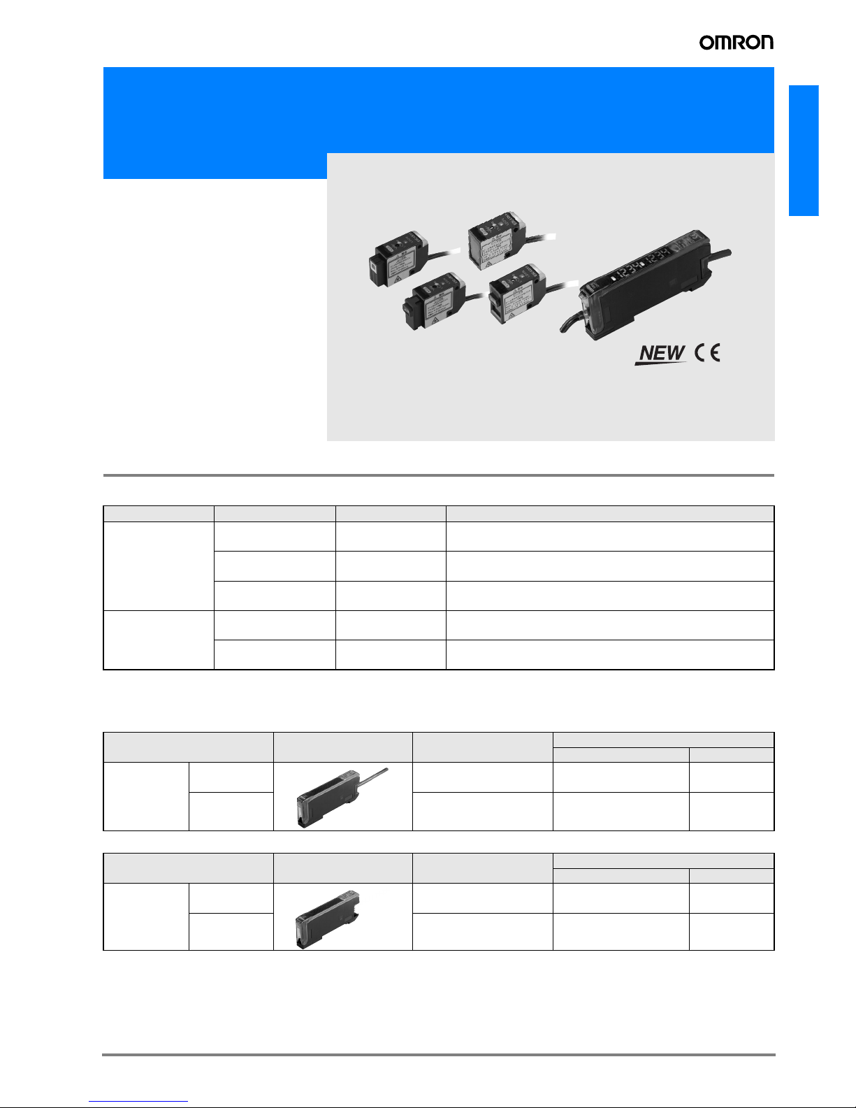
A-457E3C-LDA Series
E3C-LDA Series
Amplifier Units
*1: Communications are disabled if super-high-speed mode is selected, and the mutual interference prevention function and the communications
function for the Mobile Console will not function.
*2: The preset counter is available only with advanced, external-input models.
Nomenclature
Type Advanced, twin-output models Advanced, external-input models
Model NPN output E3C-LDA11 E3C-LDA6 E3C-LDA21 E3C-LDA7
Item PNP output E3C-LDA41 E3C-LDA8 E3C-LDA51 E3C-LDA9
Supply voltage 12 to 24 VDC ±10%, ripple (p-p) 10% max.
Power consumption 1,080 mW max. (current consumption: 45 mA max. at power supply voltage of 24 VDC)
Control output Load power supply voltage: 26.4 VDC max.; NPN/PNP (depends on model) open collector
Load current: 50 mA max.; residual voltage: 1 V max.
Response
time
Super-high-speed mode 100 µs for operation and reset 80 µs for operation and reset
Standard mode 1 ms for operation and reset
High-resolution mode 4 ms for operation and reset
Functions
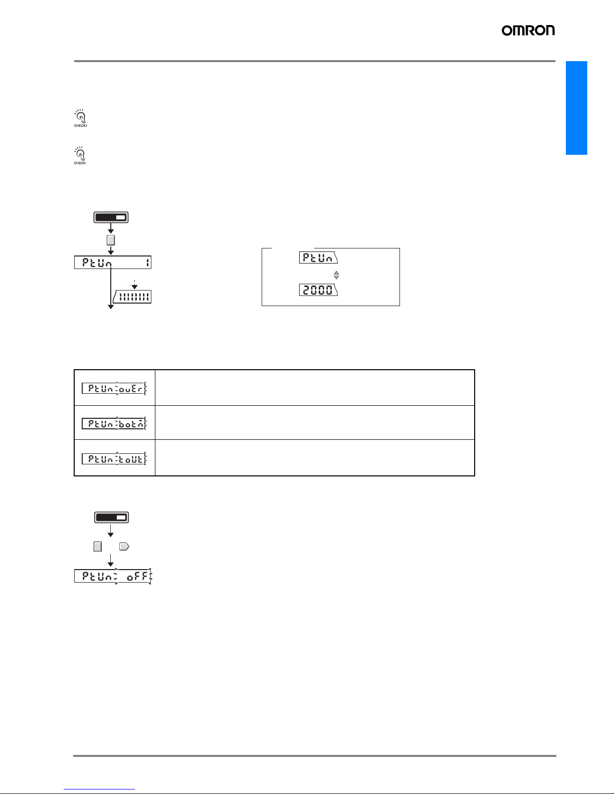
Power tuning, differential detection, timer, zero-reset, initial reset, mutual interference prevention (See note 1.), preset
counter (See note 2.), reversed display
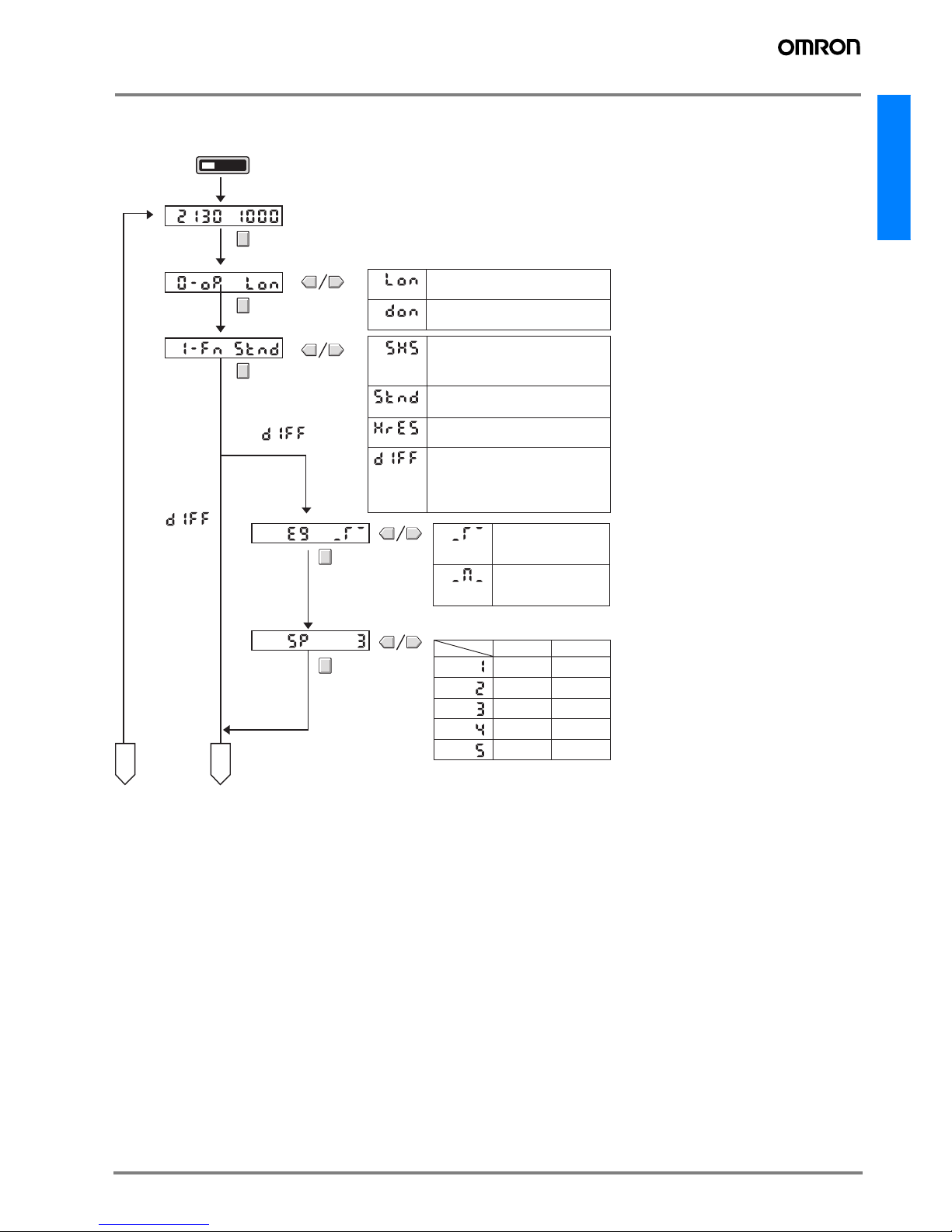
I/O settings Output setting (Select from channel 2 output, area output, or
self-diagnosis.)
External input setting (Select from teaching, power tuning,
zero reset, light OFF, or counter reset.)
Display Operation indicator for channel 1 (orange), operation indica-
tor for channel 2 (orange) Operation indicator (orange), Power Tuning indicator (orange)
Digital display
Select from the following: Incident level + threshold, incident
level percentage + threshold, incident light peak level + no in-
cident light bottom level, minimum incident light peak level +
maximum no incident light bottom level, long bar display, in-
cident level + peak hold, incident level + channel
Select from same displays as given at the left or a counter dis-
play.
Ambient illumination
(receiver side)
Incandescent lamp:10,000 lux max.
Sunlight:20,000 lux max.
Ambient temperature
Operating:Groups of 1 to 2 Amplifiers: −25°C to 55°C
Groups of 3 to 11 Amplifiers: −25°C to 50°C
Groups of 12 to 16 Amplifiers: −25°C to 45°C
(with no icing or condensation)
Storage: −30°C to 70°C (with no icing or condensation)
Ambient humidity Operating and storage: 35% to 85% (with no condensation)
Connection method Prewired
cable Separate connector Prewired
cable Separate connector
Weight (packed state) Approx. 100 g Approx. 55 g Approx. 100 g Approx. 55 g
Materials Case Polybutylene terephthalate (PBT)
Cover Polycarbonate
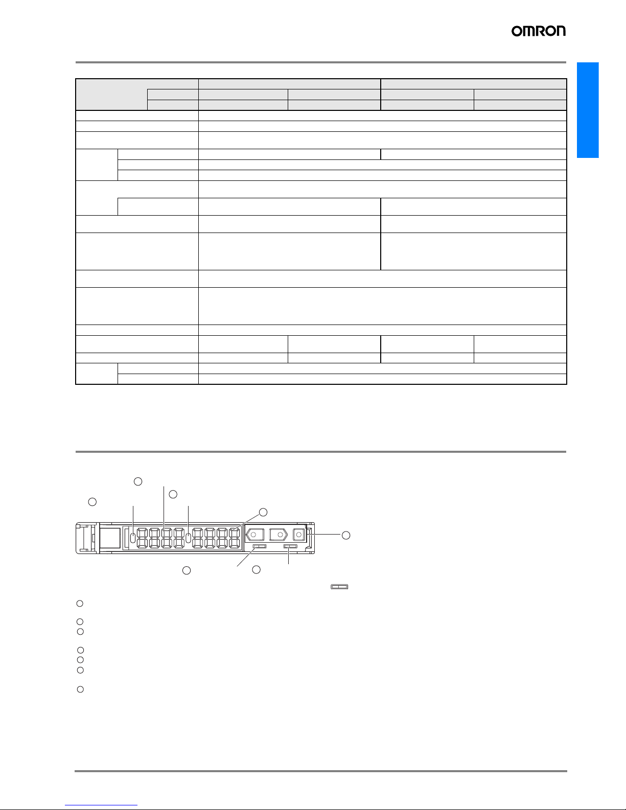
UP
SET RUN 12
DOWN MODE
LD
1 Operation indicator
2 Main display (red)
3 Twin-output Models: Operation indicator for channel 2
External-input Models: Power tuning indicator
4 Sub-display (green)
7 Operation keys
5 SET/RUN switch 6 Twin-output Models: Channel selector
External-input Models: Operation mode selector
Lit when the output is ON.
Twin-output Models: Lit when the output for channel 1 is ON.
2Displays the incident light level or the function name.
3Twin-output Models: Lit when the output for channel 2 is ON.
External-input Models: Lit when power tuning is set.
4Displays supplemental detection information, the setting of a function, etc.
5 Used to switch the mode.
6 Twin-output Models: Used to select the channel to display or set.
External-input Models: Used to select dark-ON or light-ON operation
7 Used to change the display, set functions, etc.
11