manuals.online logo
Brands
  1. Home
  2. •
  3. Brands
  4. •
  5. Omron
  6. •
  7. Accessories
  8. •
  9. Omron E3ZS User manual

Omron E3ZS User manual

CSM_E3ZS_E3FS_DS_E_2_1
1
Single-beam Safety Sensor
E3ZS/E3FS
Detects Intrusions into Hazardous
Areas with a Single Beam and
Complies with International Safety
Standards.
Features
Connect up to 4 sets of E3ZS/E3FS per B1 Module for F3SX Safety Controller
Connect to a B1 Module for F3SX to Create a Type 2 Safety Sensor
Note: The B1 Module is designed specically for E3ZS/E3FS input of t he F3SX. The safety output turns OFF when light is interrupted o r when an
error occurs with one or more of the E3ZS/E3FS Sensors connected to the B1 Module.
E3ZSE3FS
Be sure to read the “Safety Precautions” on page 15
and the “Precautions for All Safety Sensors” .
B1 Mod ule for the F 3S X
(F 3S X-EB1 shown here)
E3ZS E3FS E3FS
With Right- angle Connector s
E 3F S -10B4 2M
Dummy plug
For unused E 3ZS /E 3FS S ens or connector s
E 3F S -10B4-M1-M
F 3S X-EB1 s hown
E 3ZS -T81A
Connect s s imply and ea s ily u s ing a wide ran ge of acce ss orie s .
Authorised Distributors:-
Intech Systems Chennai Pvt. Ltd, Chennai-600 032
Ph: 4353 8888 Mob: 99 4353 8888 Fax: 044 4353 7888
E-mail: [email protected] Website: www.intechchennai.com
2
E3ZS/E3FS
Application Examples
For gaps in small-sized equipment
For gaps in small to medium-sized equipment
Protect personnel from the hazardsof gapsin
small-sized equipment or of semi-automated
machinery.
The E3ZSisaHuman Body Detection Sensor (Type 2) for
production equipment. Make sure to use it in combination with an
F3SX Safety Controller.
When used by itself, the E3ZSconformsto EN954-1 (Category 1).
No particular safety restrictionsapply to the E3ZSwhen used by
itself, except the inability to use in human detection safety
applications. We recommend using it in Light ON mode and using
it with error detection viatest input.
Note: Te st Input
Use thisfunction to enable the emitter of E3ZSto be turned ON/OFF
from outside. It ispossible to detect anumber of E3ZSerrorsby
monitoring the status of the test input and the E3ZSoutput signal.
Use asa safety measure for protection from
hazardousgapsor asguardsfor medium-sized
equipment.
The E3FSisaHuman Body Detection Sensor (Type 2) for
production equipment. Make sure to use it in combination with a
F3SX Safety Controller. A combination of E3FSand E3ZS
Sensorscan be connected to the B1 Module of the F3SX.
Note: Since the E3FShas not received any safety certification for use by
itself, make sure to connect it with an F3SX for use in safety
applications.
E3ZS/E3FS
3
Ordering Information
Sensors
Controller
Instant Breaking Models
F3SX-N-@@@R (with Relay Safety Output)
Instant Breaking Models
F3SX-E-@@@ (with DC Solid-state Safety Output)
Instant Breaking Models
F3SX-E-@@@R (with Relay Safety Output and DC Solid-state Safety Output)
Sensor method Appearance Case material Connection
method Sensing distance Output Model
Through-beam
Polybutylene
terephthalate
Pre-wired
cable (2 m)
PNP
E3ZS-T81A
ABS E3FS-10B4 2M
Brass M12
connector E3FS-10B4-M1-M
Input types
Model Width (W) Weight
E3ZS/E3FS Safety
Sensors
F3SJ/F3SN/F3SH
Safety Light Curtains
Emergency Stop
Switches Door Switches
4 sets --- 1 set --- F3SX-N-B1R 90.0 mm Approx. 0.5 kg
4 sets --- 1 set 2 sets F3SX-N-B1D1R 112.5 mm Approx. 0.6 kg
4 sets --- 1 set 4 sets F3SX-N-B1D1D1R 135.0 mm Approx. 0.7 kg
4 sets 2 sets 1 set --- F3SX-N-L2B1R 112.5 mm Approx. 0.6 kg
Input types
Model Width (W) Weight
E3ZS/E3FS Safety
Sensors
F3SJ/F3SN/F3SH
Safety Light Curtains
Emergency
Stop Switches Door Switches
4 sets --- 1 set --- F3SX-EB1 45.0 mm Approx. 0.3 kg
8sets --- 1 set --- F3SX-E-B1B1 67.5 mm Approx. 0.4 kg
4 sets --- 1 set 2 sets F3SX-E-B1D1 67.5 mm Approx. 0.4 kg
4 sets 2 sets 1 set --- F3SX-E-L2B1 67.5 mm Approx. 0.4 kg
Input types
Model Width (W) Weight
E3ZS/E3FS Safety
Sensors
F3SJ/F3SN/F3SH
Safety Light Curtains
Emergency
Stop Switches Door Switches
4 sets --- 1 set --- F3SX-E-B1R 90.0 mm Approx. 0.5 kg
Infrared lightRed light Infrared lightRed light
0.2 to 3 m
10 m
10 m
4
E3ZS/E3FS
OFF-delay Time Setting Models (Using Function Setup Software for the F3SX)
F3SX-N-@@@RR2 (with Relay Safety Output and DC Solid-state Safety Output)
OFF-delay Time Setting Models (Using Function Setup Software for the F3SX)
F3SX-E-@@@R2 (with Relay Safety Output and DC Solid-state Safety Output)
The F3SX-series Safety Controller is a multiple input, single output Controller. This is useful for individual control over the safety output when using
multiple safety input devices. Custom models are also available. Refer to the F3SX, and consult with your OMRON representative.
Accessories
Branch Connector
Dummy Plug
Cables with Connectors on Both Ends for Branch
Connector
Sensor Mounting Bracket (for E3FS)
Sensor Mounting Bracket (for E3ZS)
Mutual Interference Prevention Filter (for E3ZS)
Input types
Model Width (W) Weight
E3ZS/E3FS Safety
Sensors
F3SJ/F3SN/F3SH
Safety Light Curtains
Emergency
Stop Switches Door Switches
4 sets --- 1 set 2 sets F3SX-N-B1D1RR2 157.5 mm Approx. 0.7 kg
4 sets 2 sets 1 set --- F3SX-N-L2B1RR2 157.5 mm Approx. 0.7 kg
Input types
Model Width (W) Weight
E3ZS/E3FS Safety
Sensors
F3SJ/F3SN/F3SH
Safety Light Curtains
Emergency
Stop Switches Door Switches
4 sets --- 1 set --- F3SX-E-B1R2 90.0 mm Approx. 0.5 kg
4 sets --- 1 set 2 sets F3SX-E-B1D1R2 112.5 mm Approx. 0.6 kg
4 sets 2 sets 1 set --- F3SX-E-L2B1R2 112.5 mm Approx. 0.6 kg
Appearance Model
F39-CN3
Appearance Model
F39-CN4
Appearance Model Cable length
F39-JF1S 1 m
F39-JF2S 2 m
F39-JF5S 5 m
F39-JF10S 10 m
Appearance Model
Y92E-B18
Appearance Model
E39-L104
Dimensions Model Quantity Remarks
E39-E11 2 per Emitter and
Receiver (4 total)
For use with E3ZS-T81A. This filter prevents mutual interference by
changing the direction of polarized light of the 2 adjacent Emitter/
Receivers. However, when the filter is attached, the maximum
sensing distance of the E3ZS is reduced to 1.5 m.
0.2
1
4.9
10.8
7.4
11.231.4
E3ZS/E3FS
5
Cables with Connectors (Socket and Plug) on Both Ends
Note: Extend the cable under the following conditions.
•Overall cable length for both an E3FS Receiver connected to an F3SX and the Emitter connected to the F3SX must be within 50 m.
•Overall cable length for both an E3ZS Receiver connected to an F3SX and the Emitter connected to the F3SX must be within 100 m.
Cables with Connector (Socket) on One End
Note: Extend the cable under the following conditions.
•Overall cable length for both an E3FS Receiver connected to an F3SX and the Emitter connected to the F3SX must be within 50 m.
•Overall cable length for both an E3ZS Receiver connected to an F3SX and the Emitter connected to the F3SX must be within 100 m.
Connector Plug Assemblies, Solder Type *
*Use when connecting an E3ZS-T81A or E3FS-10B4 2M to an F39-CN3 Branch Connector.
Connector Plug Assemblies, Screw-on Type *
*Use when connecting an E3ZS-T81A or E3FS-10B4 2M to an F39-CN3 Branch Connector.
Type Cable connection direction Cable length L
(m)
DC UL standard
Model
Standard cable
Straight/straight
1XS2W-D421-C81-A
●
2XS2W-D421-D81-A
5XS2W-D421-G81-A
10 XS2W-D421-J81-A
Right angle/right angle 2XS2W-D422-D81-A
5XS2W-D422-G81-A
Straight/right angle 2XS2W-D423-D81-A
5XS2W-D423-G81-A
Right angle/straight 2XS2W-D424-D81-A
5XS2W-D424-G81-A
Robot cable
(vibration resistant) Straight/straight
1XS2W-D421-C81-R
---
2XS2W-D421-D81-R
5XS2W-D421-G81-R
10 XS2W-D421-J81-R
Type Cable connection direction Cable length L
(m)
DC UL standard
Model
Standard cable
Straight
1XS2F-D421-C80-A
●
2XS2F-D421-D80-A
5XS2F-D421-G80-A
10 XS2F-D421-J80-A
Right angle
1XS2F-D422-C80-A
2XS2F-D422-D80-A
5XS2F-D422-G80-A
10 XS2F-D422-J80-A
Robot cable
(vibration resistant)
Straight
1XS2F-D421-C80-R
---
2XS2F-D421-D80-R
5XS2F-D421-G80-R
10 XS2F-D421-J80-R
Right angle
1XS2F-D422-C80-R
2XS2F-D422-D80-R
5XS2F-D422-G80-R
10 XS2F-D422-J80-R
Applicable cable diameter
(mm)
Cable connection
direction
Connection
method Model
3 dia. (3 to 4 dia.) Straight Solder XS2G-D425
Right angle XS2G-D426
Applicable cable diameter
(mm)
Cable connection
direction
Connection
method Model
3 dia. (3 to 4 dia.) Straight Screw-on XS2G-D4S5
Right angle XS2G-D4S6
6
E3ZS/E3FS
Accessory Connection Example
Emitter Receiver
Cable with Connectors on Both Ends
(XS2W-D42@-@81-@)
Cable with Connector (Socket)
on One End
(XS2F-D42@-@80-@)
Branch Connector for the E3FS
(F39-CN3)
Cable with Connectors on Both Ends
(XS2W-D42@-@81-@)
Second Sensor
Connector
Single-beam Safety Sensor
First Sensor
Connector
Third Sensor
Connector
Fourth Sensor
Connector
Safety Controller (F3SX)
Connector Plug Assembly
(XS2G-D4@@)
EmitterReceiver
Note: Cable with Connectors on Both Ends
for Single-beam Safety Sensor Branch
Connection
(F39-JF@S) may also be used.
AB
C
AB
C
B1
Cable with Connectors on Both Ends
for Single-beam Safety Sensor Branch
Connection
(F39-JF@S)
Branch Connector for
the E3FS
(F39-CN3)
Connector Plug Assembly
(XS2G-D4@@)
Note 1: The Connector is supplied
with the F3SX.
2: Connect an F39-CN4
Dummy Plug to unused
Single-beam Safety Sensor
Connectors.
EmitterReceiver or
(E3ZS-T81A)
(E3FS-10B4-M1-M)
(E3FS-10B4 2M)
E3ZS/E3FS
7
Specifications
*1. This may vary according to the F3SX model connected to the Sensor. For details, refer to the F3SX operation manual.
*2. Connect the Sensor to an F3SX to use it as a safety device or as part of a safety system.
*3. Depending on the wiring, this may turn ON when light is interrupted.
For your safety, be sure to connect the pink receiver wire (mode selection input) to 24 VDC to turn ON when light is incident.
*4. F3SX operation manual is not included.
*5. Electro-Sensitive Protective Equipment
*6. Active Opto-electronic Protective Device
Item Model E3ZS-T81A E3FS-10B4 2M E3FS-10B4-M1-M
Sensor type Through-beam models
Safety category See Applicable standards.
Standard sensing object Opaque object: 18mm in diameter or greater Opaque object: 11 mm in diameter or greater
Lens diameter Diameter 6.7 mm / diameter 9 mm
Sensing distance 0.2 to 3 m 0 to 10 m
Response time (under
stable light incident
condition)
1.0 ms (E3ZS only) *1 2.0 ms (E3FS only) *1
Startup waiting time 100 ms
Power supply voltage (Vs) 12 to 24 VDC±10% (ripple p-p 10% max.) *2 24 VDC±10% (ripple p-p 10% max.) *2
Current consumption
(no load)
Emitter: 15 mA max.
Receiver: 20 mA max.
Emitter: 50 mA max.
Receiver: 25 mA max.
Light source (emitted
wavelength) Red LED (660 nm) Infrared LED (870 nm)
Effective aperture angle
(EAA) ±5°(at 3 m)
Control output (OSSD)
PNP transistor output, load current: 100 mA max.,
Residual voltage: 1 V max., (when load current is
less than 10 mA), Residual voltage: 2 V max. (when
load current is between 10 mA and 100 mA)
(except for voltage drop due to cable extension) *2
PNP transistor output, load current: 100 mA max.,
Residual voltage: 2 V max.
(except for voltage drop due to cable extension) *2
Output operation mode Light-ON *3
Input voltage
22.5 to 24 VDC: Emitter OFF (source current: 3 mA
max.)
Open or 0 to 2.5 V: Emitter ON (leakage current: 0.1
mA max.) *2
21.5 to 24 VDC: Emitter OFF (source current: 3 mA max.)
Open or 0 to 2.5 V: Emitter ON (leakage current: 0.1 mA
max.) *2
Indicators Emitter: Emitting (orange);
Receiver: Operation (orange), Stable (green)
Emitter: Emitting (orange);
Receiver: Output OFF (red), Output ON (green)
Test functions External test (light emission stop function by test input)
Connection method Pre-wired cable (2 m) M12 connector
Protective circuits Power supply/output reverse connection
protection, load short-circuit protection
Output reverse connection protection, load short-circuited
protection
Ambient temperature
Operating: −10 to 55°C
Storage: −10 to 70°C
(with no icing or condensation)
Operating: −20 to 55°C
Storage: −30 to 70°C
(with no icing or condensation)
Ambient humidity Operating: 35% to 85%, storage: 35% to 95% (with no icing or condensation)
Ambient operating light
intensity
Incandescent lamp: 3000 lx max (light intensity on the receiver surface).
Sunlight: 10,000 lx max (light intensity on the receiver surface).
Insulation resistance 20 MΩmin. (at 500 VDC)
Dielectric strength 1000 VAC 50/60 Hz 1 min
Degree of protection IP67 (IEC standard)
Vibration
resistance
Operating
limit 10 to 55 Hz, double amplitude: 0.7 mm, 50 min each in the X, Y, and Z directions
Malfunction 10 to 55 Hz, double amplitude: 1.5 mm, 2 h each in the X, Y, and Z directions
Shock
resistance
Operating
limit 100 m/s2, 1000 times in the X, Y, and Z directions
Malfunction 500 m/s2, 3 times each in the X, Y, and Z directions
Material Case: Polybutylene terephthalate Case: ABS Case: Brass
Weight (packed state) Approx. 120 g (for one set including 2-m cable) Approx. 150 g (for one set
including 2-m cable)
Approx. 125 g (for one set
including only Sensor)
Accessories Operation manual *4Operation manual *4, nuts for mounting Emitter/Receiver
(2 each)
Applicable
standards
Sensor only IEC 60947-5-3 (PDF-D) EN954-1 (Category 1) ---
Sensor
connected to
F3SX
IEC (EN) 61496-1 Type 2 ESPE *5,
IEC (prEN) 61496-2 Type 2 AOPD *6,
EN 954-1 (Category 2)
IEC(EN)61496-1 Type2 ESPE *5
IEC(prEN)61496-2 Type2 AOPD *6
Switching element category
(from IEC60947-5-3) DC13 (control of electromagnetic load) ---
Controller F3SX Series
8
E3ZS/E3FS
Connections
Circuit Diagram Example
F3SX-EB1 (Manual Reset)
S1: Emergency stop switch with positive opening mechanism (A165E or A22E)
S2: Reset switch
KM1, KM2: Magnetic contactor
RY1, RY2: Relay
M: Three-phase motor
E1: 24-VDC power supply (S82K)
Reset switch S2
Emergency stop switch S1
Light incident
Light interrupted
Single-beam
Safety Sensor 1
Single-beam
Safety Sensor 3
Single-beam
Safety Sensor 2
Single-beam
Safety Sensor 4
DC Solid-state Safety Output
SS1, SS2
KM1, KM2 N.C. contacts
KM1, KM2 N.O. contacts
Timing Chart
Light incident
Light interrupted
Light incident
Light interrupted
Light incident
Light interrupted
12345 678
91011121314 15 16
Circuit diagram example without
an E3FS-10B4@@@
Single-beam Safety Sensor installed.
Single-beam Safety Sensor 1
E3ZS-T81A/E3FS-10B4@@@
Single-beam Safety Sensor 2
E3ZS-T81A/E3FS-10B4@@@
Single-beam Safety Sensor 3
E3FS-10B4@@@
Single-beam Safety Sensor 4
E3ZS-T81A/E3FS-10B4@@@
Emitter Receiver
Emitter Receiver
12345 678
91011121314 15 16A2
SSC
AS3 AS2AS1SS1SS2
RY1 RY2
FB
COM
Control circuits
M
24
VDC
Te st input
Control circuits
0 V
Fuses
KM1 KM2
AC
RY1
RY2
E1: 24 VDC 24VDC
24 VDC
24 VDC
24 VDC
E1
E1
0V
KM1
KM2
S2
S1
11
12 22
21
24 VDC
E1
A1 T11 T12 T21 T22 Y1 Y2 Y3
24 VDC (brown)
0 V (blue)
Te st input (pink)
*1
0 V (blue)
Control output
(black)
24 VDC (brown)
Mode selection input
(pink) *2
24 VDC (brown)
0 V (blue)
Te st input (pink)
*1
0 V (blue)
Control output
(black)
24 VDC (brown)
Mode selection input
(pink) *2
24
VDC
0 V
24
VDC 24
VDC
0 V 0 V
Te st input
Control circuits
Te st input
Te st input
Control circuits
Control circuits
Te st input (pink) *1
0 V (blue)
Emitter Receiver
Control output
(black)
0 V (blue)
Mode selection input
(pink) *2
24 VDC (brown)
24 VDC (brown)
Emitter Receiver
Te st input (pink) *1
0 V (blue)
Control output
(black)
0 V (blue)
Mode selection input
(pink) *2
24 VDC (brown)
24 VDC (brown)
Note: 1. The above circuit diagram example conforms to Category 2.
2. The EN60204-1 stop function category is 0 (zero) for the example in
the above circuit diagram.
3. When the FB (feedback input) function of the F3SX is not used, make
setting changes with the F3SX function setup software
(F3SX-CD100-E1).
*1. The black wire is used when the Cable with Connector (Socket) on One
End (XS2F-D42@-@80-@) is connected to an E3FS-10B4-M1-M
Connector.
*2. The white wire is used when the Cable with Connector (Socket) on One
End (XS2F-D42@-@80-@) is connected to an E3FS-10B4-M1-M
Connector.
For connections, refer to the F3SX operation manual.
E3ZS/E3FS
9
I/O Circuit Diagrams
E3ZS
Circuit Diagrams (E3ZS-T81A with PNP Output)
Output mode: ON when light is incident (Light ON)
E3FS
Circuit Diagrams (E3FS-10B4@@@ with PNP Output)
Output mode: ON when light is incident (Light ON).
I/O circuit
Receiver
Emitter
*1. When using in Safety Category 2 configurations, make sure all terminals on the
B1 Module of the F3SX are properly connected. Do not connect the terminals to
another module. See the F3SX operation manual for details.
*2. Make sure to connect the pink wire (mode selection input 2) to 24 VDC.
*3. Make sure to connect to the 0V terminal when the E3ZS is not connected to an
F3SX and the test input is not used.
I/O circuit
Receiver
Emitter
*1. Make sure all terminals on the B1 Module of the F3SX are properly connected.
Do not connect the terminals to another Module. See the F3SX operation
manual for details.
*2. Make sure to connect the pink wire (mode selection input 2) to 24 VDC.
*3. Make sure to connect to the 0V terminal when the E3FS is not connected to an
F3SX and the test input is not used.
Note: The E3FS-10B4@@@ functions as a standalone Sensor when it is connected
as shown in the wiring diagram above. However, it is certified a Type 2 Safety
Sensor when it is properly connected to the B1 Module of the F3SX. This also
means it must be properly connected to an F3SX to use it as part of a safety
system.
Timing Charts
Output Modes and Timing Char
Emitter Timing Chart
Note: The F3SX performs self-diagnosis
every 20 ms.
OFF
ON
Light incident
Light interrupted
Operation
indicator
(orange)
Control
output
OFF
ON
Test input
Emission
Operation
indicator
(orange)
OFF
ON
OFF
ON
OFF
ON
1
2
4
3
Brown
Pink
Black
Blue
Main
circuit
Connectsto the 24 VDC
terminal.
Connectsto the 0 V
terminal.
Operation
indicator
Stability
indicator
Green
Orange Connectsto the control
output terminal.
*1
*1
*1
*2
1
4
3
Brown
Pink
Blue
Main
circuit
Connectsto the 24 VDC
terminal.
Connectsto the 0 VDC
terminal.
Connectsto the test input
terminal.
Orange
Emission
indicator
*1
*1
*1
*3
Timing Charts
Output Modes and Timing Chart
Emitter Timing Chart
Light incident
Light interrupted
Operation
indicator
Control
output
Red
Green
OFF
ON
Test input
Emission
Operation
indicator
(orange)
OFF
ON
OFF
ON
OFF
ON
Main
circuit
Connectsto the 24 VDC
terminal.
Connectsto the 0 V
terminal.
*1
Lit when
OFF
Lit when
ON
Green Red
1
2
4
3
Internal
resistance
of the output
IC
Connectsto the control
output terminal.
Brown
Pink
Black
Blue
*1
*2
*1
Main
circuit
Connectsto the 24 VDC
terminal.
Connectsto the 0 V
terminal.
Connectsto the test input
terminal.
Orange
Lit when
emitting 1
4
3
Brown
Pink
Blue
*1
*3
*1
*1
10
E3ZS/E3FS
Engineering Data
E3ZS
E3FS
Parallel Operating Range Mutual Interference Range Excess Gain Ratio
200
150
100
50
0
−50
−100
−150
−200
6452310
Y
X
Distance X (m)
Operating position Y (mm)
Emitter
Receiver
200
150
100
50
0
−50
−100
−150
−200 6452310
Y
X
Distance X (m)
Mutual interference range Y (mm)
Emitter
Receiver
100
10
1
0.1
128104620
Distance (m)
Excess gain ratio (times)
600
400
200
0
−200
−400
−600 128104620
Distance X (m)
Operating position Y (mm)
Y
X
Emitter
Receiver
800
600
400
200
0
−200
−400
−600
−800
128104620
Distance X (m)
Mutual interference range Y (mm)
Y
XEmitter
Receiver
10
9
8
7
6
5
4
3
2
1
03020 2510 1550
Distance (m)
Excess gain ratio (times)
E3ZS/E3FS
11
Dimensions (Unit: mm)
Sensors
Safety Controller
F3SX
For details, refer to F3SX.
25.4
17
2.1
31
2-M3
15.5
Emitting indicator (Emitter only)
Stability indicator (Receiver only)
Operation indicator (Receiver only)
10.8 10.4 3.54
Beam
6.7 dia.
8
20
Lens
Vinyl-insulated round cord with four Receiver conductorsand
three Emitter conductors, 4 dia. (cross sectionsof conductors:
0.2 mm2, insulation system: 1.1 mm dia.) Standard length: 2 m
Pre-wired Cable with ABS Resin Case
E3ZS-T81A
24
22
64.9
3.2
42.3
37
5
4
8
M18 ×1
4 dia.
16.4 dia.
4.8 dia.
9 dia.
*
*Vinyl-insulated round cord with four
Receiver conductorsand three Emitter
conductors, 4 dia. (cross sectionsof
conductors: 0.2 mm2, insulation system:
1.1 mm dia.)
Operation indicator
Lenssurface
Pre-wired Cable with ABS Resin Case
E3FS-10B4 2M
27.7
24 37
4
42.3
65.5
76
M18 × 1
M12 × 1
9 dia.
4.8 dia.
16.4 dia.
Operation indicator
Lenssurface
Connector with Metal Case
E3FS-10B4-M1-M
12
E3ZS/E3FS
Accessories (Order Separately)
14
3
2
143
2
14
2
3
4
3
2
1
4
3
2
1
12 43
50.6
24.6
29
*
*The molded part B of the Connector isblack.
Wiring Diagram
Branch Connector
F39-CN3
20
15
26
Dummy Plug
F39-CN4 32±0.2
17 max.
7
30
47 max.
18 dia.
Material: Plastic
Hexagonal bolt: M5 x 32
Sensor Mounting Bracket (for E3FS)
Y92E-B18
R1
R1
R1.7 R1.7 3.4
5.8 12.5 (13.7)
4.5
6
29
3.4
R20
14°
Two, 3.2 dia.
3.5
16
R3.5
37.8
(39)
3.2
R25.4
10°
R1.6
8.8
Sensor Mounting Bracket (for E3ZS)
E39-L104
Material: Stainless steel (SUS304)
E3ZS/E3FS
13
L *30±10 26
20
15
Vinyl-insulated round cord, 6 dia. (gray),
4 conductors(cross sectionsof conductors: 0.5 mm2,
insulation system: 1.70 mm dia.),
Standard length: L *
*Dimensionswill vary with the model as shown in the table on the left.
40.7
14.9 dia.
Cables with Connectors on Both Ends for Branch Connection
F39-JF1S
F39-JF2S
F39-JF5S
F39-JF10S
Model L (mm)
F39-JF1S 1,000
F39-JF2S 2,000
F39-JF5S 5,000
F39-JF10S 10,000
+150
0
+150
0
+300
0
+300
0
Cables with Connectors (Socket and Plug) on Both Ends
XS2W-D421-C81-A (L=1m)
XS2W-D421-D81-A (L=2m)
XS2W-D421-G81-A (L=5m)
XS2W-D421-J81-A (L=10m)
XS2W-D421-C81-R (L=1m)
XS2W-D421-D81-R (L=2m)
XS2W-D421-G81-R (L=5m)
XS2W-D421-J81-R (L=10m)
14.9 dia. 14.9 dia.
40.7
L
44.7
6 dia.
XS2W-D422-D81-A (L=2m)
XS2W-D422-G81-A (L=5m)
L
14.9 dia.
32.3
28.3
25.3 25.3
6 dia.
XS2W-D423-D81-A (L=2m)
XS2W-D423-G81-A (L=5m)
L
14.9 dia.
32.3
25.3
40.7
14.9 dia.
6 dia.
XS2W-D424-D81-A (L=2m)
XS2W-D424-G81-A (L=5m)
L
28.3
25.3
14.9 dia.
44.7
6 dia.
14
E3ZS/E3FS
Cables with Connector (Socket) on One End
XS2F-D421-C80-A (L=1m)
XS2F-D421-D80-A (L=2m)
XS2F-D421-G80-A (L=5m)
XS2F-D421-J80-A (L=10m)
XS2F-D421-C80-R (L=1m)
XS2F-D421-D80-R (L=2m)
XS2F-D421-G80-R (L=5m)
XS2F-D421-J80-R (L=10m)
6 dia.
40.7
14.9 dia.
L50
30 5
45°
5 dia.
M12 45°
5 dia.
M12
DC AC
6 dia.
25.3
28.3
L
50
30 5
45°
5 dia.
M12
45°
5 dia.
M12
DC AC
XS2F-D422-C80-A (L=1m)
XS2F-D422-D80-A (L=2m)
XS2F-D422-G80-A (L=5m)
XS2F-D422-J80-A (L=10m)
XS2F-D422-C80-R (L=1m)
XS2F-D422-D80-R (L=2m)
XS2F-D422-G80-R (L=5m)
XS2F-D422-J80-R (L=10m)
Connector Plug Assemblies, Solder Type
XS2G-D425
5 dia.
14.9 dia.
47.1
14.2 dia.
45°
5 dia.
45°M12
DC AC
XS2G-D426 35.7
M12 × 114.9 dia.
45°
23
5 dia.
DC
58.7
14 dia.20 dia.
M12 × 1
14.9 dia.
Connector Plug Assemblies, Screw-on Type
XS2G-D4S5
14.9 dia.
39.7
39.6
20 dia.
M12 × 1
14 dia.
XS2G-D4S6
E3ZS/E3FS
15
Safety Precautions
!WARNING
Refer to the “Precautions for All Safety Sensors ” for calculating the
Safety distance.
Preventing Mutual Interference
Observe the following items during installation to prevent
Single- beam Safety Sensors from interfering with each other or with
Safety Light Curtains.
xLeave ade quate space between the Sensors during installation.
(Refer to the instruction manuals for the E3ZS/E3FS and the
F3SN/F3SH.)
xUse bae plates to separate Sensors.
xAlternate Emitters and Receivers during installation. (See the
gure below.)
Check for mutual interference between Single- beam Safety Sensors
or Safety Light Curtains connected to the same or dierent Control
Units before nalizing placement and starting normal operation.
!WARNING
OMRON's Single-beam Safety Sensor Input Module (B1
Module) from the F3SX Series is the only Controller that
can be used for the E3ZS-T81A/E3FS-10B4 (type
2). Normal operation may not be possi ble if another
Single- beam Sensor Controller is used.
The Sensor cannot be used as part of a safety system
when the mode selection input of the Single-beam Safety
Sensor Receiver is connected to 0 V because the Sensor
will turn ON when light is interrupted (Dark ON). Be sure
to connect the mode selection input to 24 VDC if you want
the Sensor to turn ON when light is incident (Light ON).
When installing multiple Safety Light Curtains,
Multi-beam Safety Sensors, and Single-beam Safety
Sensors, take necessary steps to prevent mutual
interference. Otherwise detection may fail and serious
injury may result.
Emitter
Receiver
Emitter
Receiver
Receiver
Emitter
Receiver
Emitter
Authorised Distributors:- Intech Systems Chennai Pvt. Ltd
S-2, Thiru. Vi. Ka. Industrial Estate, Guindy, Chennai-600 032
Ph: 4353 8888 Mob: 99 4353 8888 (Board Line) Fax: 044 4353 7888
E-mail: [email protected] Website: www.intechchennai.com

This manual suits for next models

1

Other Omron Accessories manuals

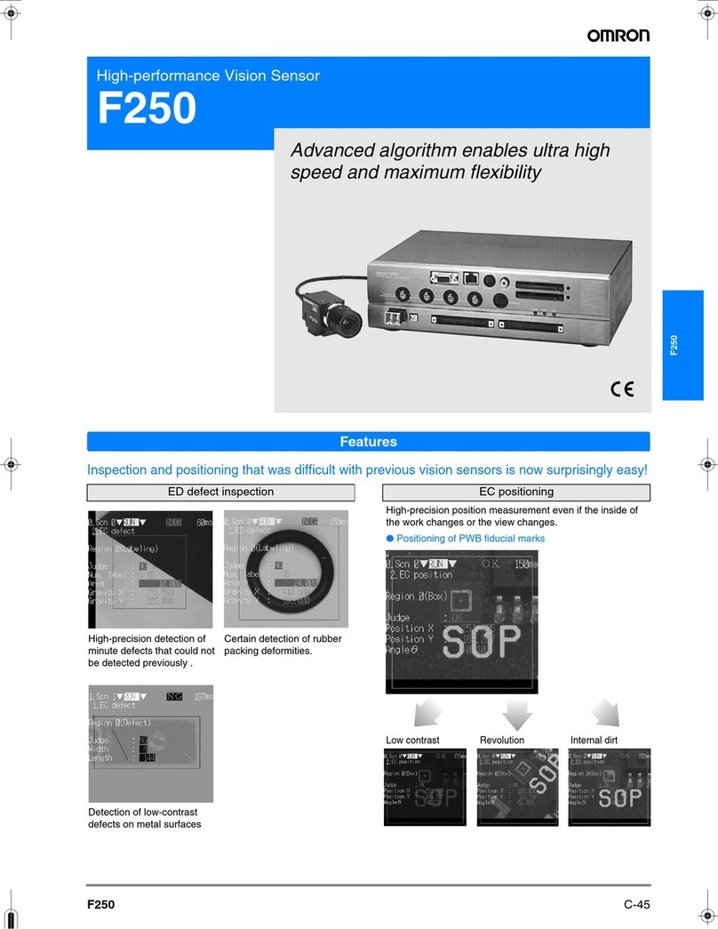
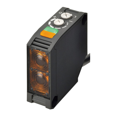
Omron E3Z series User manual

Omron

Omron E3Z series User manual

Omron F400 Reference manual

Omron

Omron F400 Reference manual

Omron ES1B - DATASHEET 1 User manual

Omron

Omron ES1B - DATASHEET 1 User manual

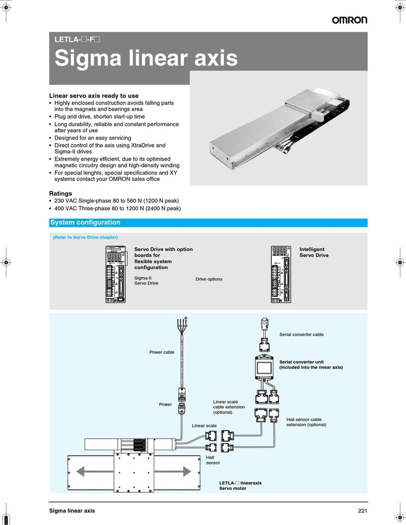
Omron SIGMA LINEAR AXIS - User manual

Omron

Omron SIGMA LINEAR AXIS - User manual

Omron E3F3 User manual

Omron

Omron E3F3 User manual

Omron E3X-DA-S Series User manual

Omron

Omron E3X-DA-S Series User manual

Omron E2K-L User manual

Omron

Omron E2K-L User manual

Omron ZG2 Series User manual

Omron

Omron ZG2 Series User manual

Omron 2JCIE-BL01 User manual

Omron

Omron 2JCIE-BL01 User manual

Omron ZJ-SD Series User manual

Omron

Omron ZJ-SD Series User manual

Omron Z4M-W10 User manual

Omron

Omron Z4M-W10 User manual

Omron ZFX-C10 COMMUNICATION Operating manual

Omron

Omron ZFX-C10 COMMUNICATION Operating manual

Omron FJ Series User manual

Omron

Omron FJ Series User manual

Omron E2KQ-X User manual

Omron

Omron E2KQ-X User manual

Omron ZFX-C10 COMMUNICATION User manual

Omron

Omron ZFX-C10 COMMUNICATION User manual

Omron E3JK-T series User manual

Omron

Omron E3JK-T series User manual

Omron FZ3 Series User manual

Omron

Omron FZ3 Series User manual

Omron ZX1-LD User manual

Omron

Omron ZX1-LD User manual

Omron E39 Series User manual

Omron

Omron E39 Series User manual

Omron F250-C50 C55 - SETUP 09-2001 User manual

Omron

Omron F250-C50 C55 - SETUP 09-2001 User manual

Omron MS4800E User manual

Omron

Omron MS4800E User manual

Omron E3ZM-V series User manual

Omron

Omron E3ZM-V series User manual

Omron E2C-EDA Series User manual

Omron

Omron E2C-EDA Series User manual

Omron B5W-LB21 Series User manual

Omron

Omron B5W-LB21 Series User manual

Popular Accessories manuals by other brands

Serene House Sprout Serene Pod instruction manual

Serene House

Serene House Sprout Serene Pod instruction manual

Velleman EMS109 user manual

Velleman

Velleman EMS109 user manual

Renson Lapure quick start guide

Renson

Renson Lapure quick start guide

Panasonic MAZLxxxH Series Specifications

Panasonic

Panasonic MAZLxxxH Series Specifications

TORREY PINES SCIENTIFIC EchoTherm IN35-12VDC operating manual

TORREY PINES SCIENTIFIC

TORREY PINES SCIENTIFIC EchoTherm IN35-12VDC operating manual

Goobay 44170 user manual

Goobay

Goobay 44170 user manual

Cardinal Priefert 190P Quick setup

Cardinal

Cardinal Priefert 190P Quick setup

Champion Power Equipment 100333 Parts information

Champion Power Equipment

Champion Power Equipment 100333 Parts information

Johnson J8 user guide

Johnson

Johnson J8 user guide

DAVIS Wireless Temperature/Humidity Station install guide

DAVIS

DAVIS Wireless Temperature/Humidity Station install guide

SKF CMDT 391 user manual

SKF

SKF CMDT 391 user manual

Tektronix P6047 instruction manual

Tektronix

Tektronix P6047 instruction manual

Fluid Gaming EK-AC Radeon RX 5700 +XT user guide

Fluid Gaming

Fluid Gaming EK-AC Radeon RX 5700 +XT user guide

Festo VMPAF-FB-PS Series Assembly instructions

Festo

Festo VMPAF-FB-PS Series Assembly instructions

EnOcean TRIO2SYS Installation and operating manual

EnOcean

EnOcean TRIO2SYS Installation and operating manual

AMC SS14 manual

AMC

AMC SS14 manual

Belimo ZG-JSL Mounting installation guide

Belimo

Belimo ZG-JSL Mounting installation guide

Asus Pen 2.0 user manual

Asus

Asus Pen 2.0 user manual

manuals.online logo
manuals.online logoBrands
  • About & Mission
  • Contact us
  • Privacy Policy
  • Terms and Conditions

Copyright 2025 Manuals.Online. All Rights Reserved.