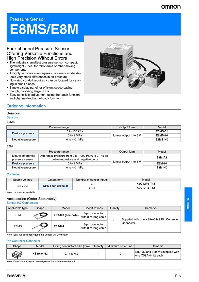
Omron E2C-CR5B User manual

1
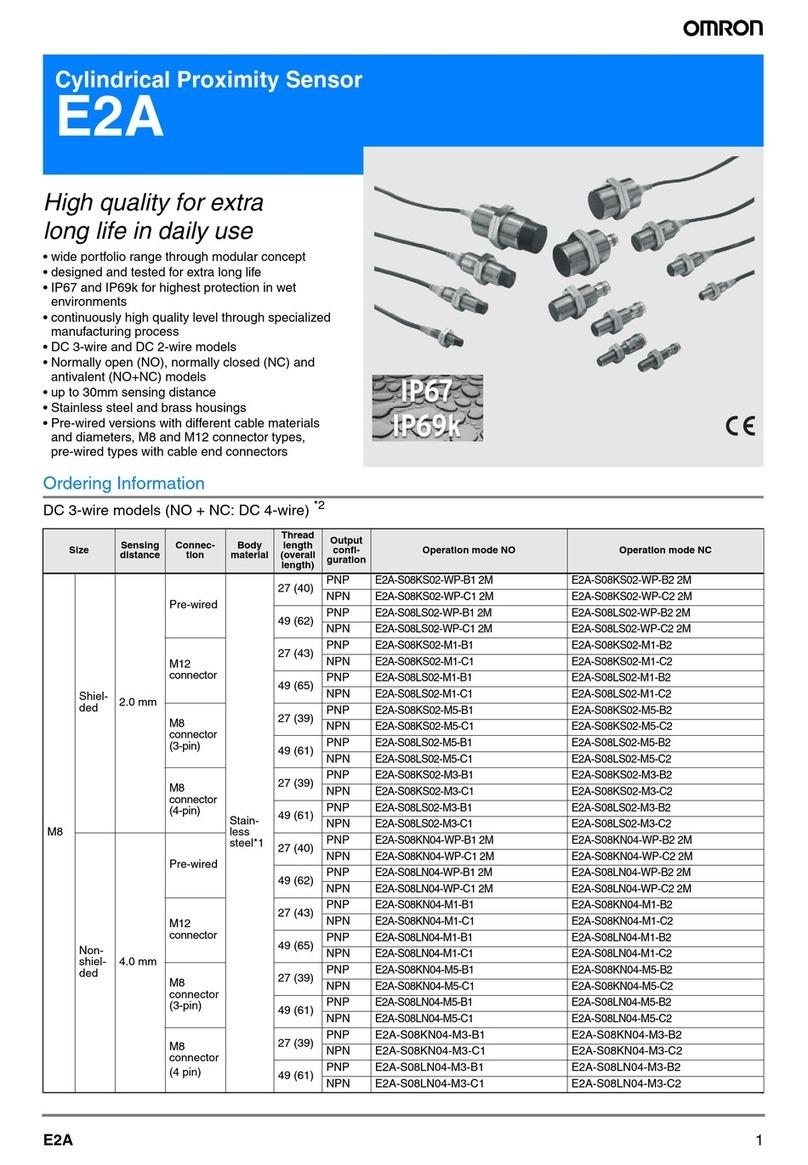
Inductive Proximity Sensor E2C
Variable Sensing Distance and
Differential Travel Allow a Wide Range
of Applications
Various Sensing Heads available in outer diame-
ters from 2.0 to 40 mm.
Operation
and stability indicators (LED) in Amplifier
Unit allow easy monitoring of stable operation.
Amplifier
Unit has wide-ranging operating
voltages,
10 to 30 VDC or 90 to 264 VAC.
Small differences in size, distance, and materials
can be detected.
Ordering Information
AC 2-wire Models
Size Shield Sensing
di t
Maxi- Sensor
Hd
Amplifier Unit
g
distance mum
operat-
ing dis
-
tance
Head Multi-function Single-function Self-
diag-
nostic
function
AC DC
(PNP,
NPN)
DC
(NPN) DC
(PNP,
NPN)
DC
(NPN) DC
(PNP) DC
(NPN)
2.0 dia.
Un-
shielded
(see
note1)
0.5 mm 1.2 mm
E2C-
CR5B E2C-
AK4A E2C-
AM4A --- --- E2C-
GE4B E2C-
GF4B ---
3.5 dia.
Shielded
0.8 mm 1.8 mm
E2C-
CR8A E2C-
JCA4 E2C-
WH4AF
(
E2C-
GE4A E2C-
GF4A E2C-
JCA4P
(
3.8 dia.
1 mm 2 mm
E2C-
CR8B (see
note 2)
E2C
-
(see
note 3)
M5 E2C-
X1A
E2C
-
WH4A
5.4 dia.
E2C-
C1A
M8
1.5 mm
3 mm
E2C-
X1R5A
M12
2 mm 5 mm
E2C-
X2A --- --- ---
M18
5 mm
10 mm
E2C-
X5A
M30
10 mm 18 mm
E2C-
X10A
40 dia.
Un-
shielded
20 mm 50 mm
E2C-
C20MA
Note: 1.
The E2C-CR5B cannot be flush-mounted in metal even though the E2C-CR5B is of a shielded construction.
2.
Use the E2C-WH4AF in combination with the S3D8 Sensor Controller
3.
The E2C-JCA4P is an Amplifier Unit with self-diagnostic output for DIN track mounting.

E2C E2C
2
Specifications
Sensor Heads
Model E2C-CR5B E2C-CR8A
E2C-CR5B E2C-X1A
E2C-C1A E2C-
X1R5A E2C-X2A E2C-X5A E2C-X10A E2C-
C20MA
Sensing
object
Magnetic metals (Refer to
Engineering Data
for non-magnetic metals.)
Standard sensing
object
Iron: 5 x 5 x
1 mm
Iron: 5 x 5
x 1 mm
Iron: 5 x 5
x 1 mm
Iron: 8 x 8
x 1 mm
Iron: 12 x
12 x 1 mm
Iron: 18 x
18 x 1 mm
Iron: 30 x
30 x 1 mm
Iron: 50 x
50 x 1 mm
Stable sensing range
(within rated
temperature range)
0 to 0.5 mm
0 to
0.8 mm
0 to 1 mm
0 to
1.5 mm
0 to 2 mm 0 to 5 mm
0 to 10 mm 0 to 20 mm
Safety sensing range
(0°
C to 40
°C)
0 to 0.7 mm
0 to
1.2 mm
0 to
1.5 mm
0 to 2 mm
0 to
2.5 mm
0 to 7 mm
0 to 15 mm 0 to 28 mm
Maximum operating
distance (at 23
°C)
1.2 mm 1.8 mm
2 mm 3 mm 5 mm
10 mm 18 mm 50 mm
Response frequency
(see note 1)
1 kHz 800 Hz 350 Hz 100 Hz 50 Hz
Ambient temperature
Operating:
–10°
C to
55°C
Operating: –25
°
C to 70
°
C (with no icing)
Ambient humidity
Operating: 35% to 95%
Temperature
influence ±
25% max.
of the sens
-
ing dis
-
tance at
23°
C in a
tempera-
ture range
of –10
°C
and 55
°C
±
15% max. of the sensing distance at 23
°
C in a temperature range of –25
°
C and 70
°C
V
ibration resistance
Malfunction: 10 to 55 Hz, 1.5-mm double amplitude for 2 hrs each in X, Y
, and Z directions
Shock resistance
Malfunction: 500 m/s
2
(approx. 50G) for 3 times each in X, Y
, and Z directions
Enclosure rating
IEC IP64 IEC IP67
Cable length (see
note 2)
3-m
shielded
cable
3-m high-frequency coaxial cable (5 m
max.)
3-m high-frequency coaxial cable (10 m max.)
W
eight (with 3-m
cable) Approx.
10 g
Approx.
40 g
Approx.
45 g
Approx.
50 g
Approx.
60 g
Approx.
140 g
Approx.
270 g
Approx.
300 g
Material Case
Stainless steel
Brass
Sensing
surface ABS resin
Cable Polyethylene
Note: 1. Response
frequencies are minimum values applicable to DC solid-state control
output used to measure standard sensing objects,
each
separated from one another with a distance that is
double the side dimension of the sensing object and located at a distance
that
is half the maximum sensing distance.
2. The
cable length varies with the Amplifier Unit and Sensor Head in combination. Refer to the table on the next page. The character
-
istic
impedance of the coaxial cable is 50
Ω.

E2C E2C
3
Cable Lengths vs. Amplifier Unit and Sensor Head Combinations
Amplifier
Uit
Sensor
Head
p
Unit E2C-
CR5B E2C-
CR8A E2C-
CR8B E2C-X1A E2C-C1A E2C-
X1R5A E2C-X2A E2C-X5A E2C-
X10A E2C-
C20MA
E2C-GE4B
3 m only
--- --- --- --- --- --- --- --- ---
E2C-GF4B
y
--- --- --- --- --- --- --- --- ---
E2C-GE4A ---
3 m only
--- --- --- ---
E2C-GF4A ---
y
--- --- --- ---
E2C-WH4A ---
3 m or 5 m only
Set the pins of the cable length selector properly (see
--- --- --- ---
E2C-WH4AF ---
S
et the pins o
f
the cable length selector properly
(
see
note). --- --- --- ---
E2C-JC4AP ---
1 to 3 m: Short-circuit the cable length selector terminals.
3 to 5 m: Open the cable length selector terminals.
--- --- ---
E2C-JC4A ---
3 m only
--- --- ---
E2C-AM4A
3 m or
5 m only
with all
pins of
the cable
0 to 5 m
Set the pins of the cable length selector properly (see
note).
0 to 10 m
Set the pins of the cable length selector
properly (see note).
E2C-AK4A
t
h
e ca
bl
e
length
selector
set to the
left.
Note:
Refer to page
12 for cable length selection.
Amplifier Units
Model E2C-AK4A E2C-AM4A E2C-JC4A
E2C-JC4AP E2C-GE4jE2C-GF4jE2C-WH4A E2C-WH4AF
Power
supply
voltage (Operating
voltage range)
100 to
240 V
AC (90
to 264 V
AC)
50/60 Hz
12 to 24 VDC (10 to 30 VDC), ripple (p-p): 10% max. (see note 1)
Current consumption
55 mA max. 50 mA max. 45 mA max. 25 mA max. 25 mA max.
Sensing distance
adjustable range
(see note 2)
20% to 100% of rated sensing distance with a
4-turn potentiometer
20% min. of rated sensing
distance
20% to 100% of rated
sensing distance with a
4-turn potentiometer
Differential travel
1% to 5% of rated sensing
distance (see note 3)
10% max. of sensing distance
Response
time DC solid-
state
Refer to the response frequency of the Proximity Sensor in use.
Relay
20 ms max.
---
Control
output DC solid-
state
50 mA max.
at 40 V with
a residual
voltage of
2 V max.,
transistor
photocoupler
200 mA max.
at 40 V with a
residual
voltage of
1.5 V max.,
NPN and
PNP open
collector
output
100 mA max.
at 40 V with a
residual
voltage of
0.7 V max.
(1 V max. for
E2C-JC4AP),
NPN open
collector
output
100 mA max.
at 40 V with
a residual
voltage of
1.5 V max.,
NPN output
with a
resistance of
4.7 k
Ω
100 mA max.
at 40 V with
a residual
voltage of
1.5 V max.,
PNP output
with a
resistance of
4.7 k
Ω
200 mA max.
at 40 V with
a residual
voltage of
1.5 V max.,
NPN and
PNP open
collector
outputs
200 mA max.
at 40 V with
a residual
voltage of
1.5 V max.,
NPN and
PNP open
collector
output
Connector
output:
50 mA max.
with a
residual
voltage of
2 V max.,
Transistor
photocoupler
Relay
2 A at 250
VAC, cos ø =
1 (resistive
load) (see
note 4),
SPDT relay
output
---

E2C E2C
4
Model E2C-WH4AFE2C-WH4AE2C-GF4jE2C-GE4jE2C-JC4A
E2C-JC4AP
E2C-AM4AE2C-AK4A
Output configuration NO/NC selectable
Self-diagnostic
output --- E2C-JA4AP
only.
Output
transistor
turns ON:
Sensor wire
burnout or
unstable
detection
50 mA max.
at 40 V with a
residual
voltage of 1 V
max., NPN
open collector
---
T
imer function
--- OFF-delay:
40±
10 ms
---
Cable length
compensation
Mode selection with a
4-throw switch E2C-JC4AP
only.
3 m/5 m ter
-
minals with
short bar
Short-cir-
cuited: 1 to
3 m
Open: 3 to
5 m
---
3 m/5 m selectable
Indicator
Operation indicator and
stability indicator
Operation
indicator and
stability
indicator
Operation indicator
Ambient temperature
Operating: –10
°
C to 55
°
C (with no icing)
Ambient humidity
Operating: 35% to 85% (35% to 95% for the E2C-JC4AP)
Temperature
influence ±
10% max. of sensing distance at 23
°
C in temperature range of –10
°
C and 55
°C
V
oltage influence
DC models:
±
1% max. of sensing distance in rated voltage range of
±
20% of the rated power supply voltage
AC models:
±
1% max. of sensing distance in rated voltage range of
±
10% of the rated power supply voltage
Insulation resistance
50 M
Ω
(at 500 VDC) between current carry parts and case
Dielectric strength
DC models: 1,000 V
AC (50/60 Hz) for 1 min between current carry parts and case
AC models: 1,500 V
AC (50/60 Hz) for 1 min between current carry parts and case
V
ibration resistance
Malfunction: 10 to 25 Hz,
2-mm double amplitude for
2 hrs each in X, Y
, and Z
directions
Malfunction:
10 to 55 Hz,
1.5-mm
double
amplitude for
2 hrs each in
X, Y
, and Z
directions
Malfunction: 10 to 25 Hz,
2-mm double amplitude for
2 hrs each in X, Y
, and Z
directions
Malfunction: 10 to 25 Hz,
2-mm double amplitude for
2 hrs each in X, Y
, and Z
directions
Shock resistance
Malfunction: 100 m/s
2
(approx. 10G) for 3 times each in X, Y
, and Z directions
Life expectancy
Mechanical:
10,000,000
times min.
Electrical:
100,000
times min.
---
Weight Approx.
250 g
Approx.
140 g
Approx. 50 g
(E2C-JC4AP:
Approx. 80 g)
Approx. 20 g Approx. 80 g
Note: 1. A
power supply with full-wave rectification with an average output of 24 VDC
±
10% can be used with all E2C Amplifier Units except
the E2C-GE4j.
2. The
sensing distance adjustable range indicates the sensing range of the E2C Amplifier Unit in satisfactory operation with Sensors.
3. The
dif
ferential travel is adjustable
within a range between 1% and 20% of the rated sensing distance if the E2C-CR5B is used.
4.
The built-in Relay is the G2R-1
14P-V
-VS with an operating voltage of 12 V
.
5.
The weight of each model does not include the weight of the connecting socket.

E2C E2C
5
Operation
Output Circuits
Main
circuit
50 mA max.
2.2
Ω
47 V
Output (+)
Output (–)
E2C-AK4A (AC-switching Amplifier Unit)
Note:
Relay contact output is incorporated.
Main
circuit 2.2
Ω
47 V
47 V
200 mA max.
12 to 24 VDC
Output 1 (PNP)
Output 2 (NPN)
0 V
E2C-AM4A (DC-switching Amplifier Unit)
E2C-GE4j(DC-switching Amplifier Unit) E2C-GF4j(DC-switching Amplifier Unit)
Main
circuit
4.7
k
Ω
47 V
100 mA
max.
12 to 24 VDC
Output
0 V
2.2
ΩMain
circuit
4.7 kΩ
47 V
100 mA max.
12 to 24 VDC
Output
0 V
2.2
Ω
E2C-JC4A (DC-switching Amplifier Unit) E2C-JC4AP
Main
circuit
12 to 24 VDC
Brown (Red)
Output
Black (White)
0 V
Blue (Black)
47 V
2.2
Ω
Load
12 to
24 VDC
100 mA
max.
0 V
Brown (Red)
Black
(White)
Output
Blue (Black)
Orange (Yellow)
Self-diagnostic
output (50 mA
max.)
Operation
indicator Stability
indicator
(Red) (Green)
2.2
Ω
3.9
Ω
ZD
: V
Z=40 V
Main
circuit
Note: Voltage
output from E2C-GE4
j
will be available if the operation selector
is
set to NC. When using voltage output, be sure to reset the E2C-GE4
j
after
the E2C-GE4
j
is turned on, at which moment the E2C-GE4
j
gen
-
erates
a pulse for
approximately 60 ms. No such pulse is generated from
the E2C-GF4 with PNP output.
100 mA max.
E2C-WH4A (DC-switching Amplifier Unit) E2C-WH4AF
(DC-switching Amplifier Unit with Connector Output)
Main
circuit
12 to 24 VDC
0 V
2.2
Ω
2.2
Ω
47 V
47 V
200 mA max.
Output 2 (PNP)
Output 1 (NPN)
12 to 24 VDC
0 V
2.2
Ω
2.2
Ω
47 V
47 V
200 mA max.
Output 2 (PNP)
Output 1 (NPN)
2.2
Ω
47 V
50 mA max.
Connector output
Main
circuit

E2C E2C
6
Operating Charts
E2C-Aj4A
Mode
selector
Yes
No
Sensing
object
Relay output
(transistor output)
Operation
indicator ON
OFF
E2C-Gj4j
Mode
selector
Yes
No
Sensing
object
Transistor output
(voltage output)
Operation
indicator ON
OFF
Operation
Reset ON
OFF
E2C-JC4A
Yes
No
Sensing
object
Mode
selector
Operation
indicator ON
OFF
Output transistor
, ter
-
minals short-circuited
(OFF-delay enabled)
Output transistor
, ter
-
minals open (OFF-
delay disabled)
E2C-JC4AP
Mode
selector
Yes
No
Sensing
object
Timer switch ON
(OFF-delay enabled)
Timer switch OFF
(OFF-delay disabled)
Output transistor
Operation
indicator ON
OFF
E2C-WH4A(F)
Mode
selector
Yes
No
Sensing
object
Transistor
output
Operation
indicator ON
OFF
Self-diagnostic Function
The
output transistor of self-diagnostic output will turn on instantly if the E2C detects one of the following events.
1.
Sensor wire burnout
2. The
operation indicator is ON for 0.3 s or more while the sensing object is at 93% to 100% of the sensing distance. This will occur if the
sensing
object is in the wrong position, for example.
3. The
operation indicator is OFF for 0.3 s or more while the sensing object located at 100% to 107% of the sensing distance. This will occur
if
the Sensor is influenced by the background of the sensing object, for example.
Sensor W
ire is Burnt Out
Sensor W
ire is Connected
Sensing
object
Control
output
(NO)
Self-diagnostic
output
Operation
Stability
Burnout Normal Burnout Normal
Red
Green
Red
Sensing
distance
Set distance
Operation
Stability
0.3 s min. 0.3 s min.
Indicator
Yes
No
Control
output (NO)
Self-diagnostic
output
Indicator
*Self-diagnostic
output will be ON if the sensing object moves at
slow
speed, in which case, add an ON-delay timer circuit.
Note: Replace the 93% value with 96% and the 107% value
with
104% for the E2C-X2A.
Red
Green
GreenGreen

E2C E2C
7
Indicators
•The
operation indicator is lit when the sensing object is near the
sensing
distance.
•The stability indicator is lit when the sensing object position is
less
than 95% or more than 107% of the sensing distance. The
stability indicator indicates the range in which each sensing
object
is detected smoothly
.
Stable non-
sensing area
Operation indicator
(red)
Not lit
Stability indicator
(green)
Stable sensing
area Lit
Set distance x
approx. 1.07
(see note)
Lit
Lit
Set distance
Set distance x
approx. 0.93
(see note)
Not lit
Note: Replace the 1.07 value with 1.04 and the 0.93 value with
0.96
for the E2C-X2A.
Sensitivity Adjustment
1. Initial Adjustment
After
the E2C Amplifier Unit is turned on, adjust the following Sensor according to the status of each indicator without a sensing object.
•Status of
Indicators •Adjustment
E2C-JC4A
Multi-function Model
E2C-Aj
4A Multi-function Model
Lit
Operation
A
B
C
D
Sensitivity Operation Sensitivity Sensitivity
E2C-Gj4j
Single-function Model
E2C-WH4A(F) Multi-function Model
No adjustment is required.
Not Lit
T
urn the sensitivity adjuster coun
-
terclockwise until the operation in
-
dicator turns of
f.
Lit Lit
Lit
Lit
Not Lit
Not Lit Not Lit
Not Lit
Indicator
mode
•
Status of Indicators
•Adjustment
T
urn the sensitivity adjuster
counterclockwise so that the op
-
eration indicator turns of
f and the
stability indicator is lit (i.e., the
E2C Amplifier Unit is in mode D).
No adjustment is required.
2. Sensitivity Adjustment
Item E2C-Gj4j
Single-function Model
E2C-WH4A(F) Multi-function Model
Step 1 2 3 1 2 3
Sensing
Sensitivity
adjuster --- --- --- ---
Adjustment
Obtain the
sensing distance
X from the set
distance S
divided by 0.8.
Determine S so
that X will be
less than the
maximum
sensing
distance.
Locate the
Sensor so that
the distance
between the
Sensor and
sensing object is
X. T
urn the
sensitivity
adjuster
clockwise until
the operation
indicator is lit.
Return the
Sensor to the
previous position
so that the
distance
between the
Sensor and
sensing object is
S. Secure the
position of the
Sensor to
complete the
sensitivity
adjustment.
Note: If the E2C Amplifier Unit malfunctions due to radical ambient temperature changes, shorten the distance between the Sensor and
sensing
object to 80% maximum of the set distance.

E2C E2C
8
Model E2C-Aj
4A and E2C-JC4A Multi-function Models (See note 2)
Step 1 2 3 4
Sensing ---
Sensing
object
Sensing
object
Sensing
object
Sensitivity adjuster
---
Adjustment
Set the MD adjuster to
the center between “Min”
and “Max.”
Locate the sensing
object in the adjustment
range of sensing
distance and turn the
sensitivity adjuster
clockwise slowly until the
operation indicator is lit.
Move the sensing object
for a necessary
dif
ferential travel
distance (i.e., 1% to 5%
of the rated sensing
distance) and turn the
MD adjuster
counterclockwise slowly
until the operation
indicator turns of
f. Then
move the sensing object
and check that the
Sensor detects the
object when the object is
in the sensing distance
range.
Shorten the distance
between the Sensor and
sensing object and fix
the position of the
Sensor where both the
operation indicator and
stability indicator are lit
to complete the
sensitivity adjustment.
Note: 1. If
the E2C Amplifier Unit malfunctions due to radical ambient
temperature changes, further shorten the distance between the Sen
-
sor
and sensing object to 80% maximum of the set distance.
2.
The E2C-JC4A has no function to adjust dif
ferential travel. Therefore, take steps 2 and 4 only
.
Adjustment
Model E2C-JC4AP
Step 1 2 3
Sensing
Sensing
object
Sensing
object
Sensing
object
Sensitivity
adjuster
--- ---
Adjustment
Obtain the sensing distance X
from the set distance S divided
by 0.8. Determine S so that X
will be less than the maximum
sensing distance.
Locate the Sensor so that the
distance between the Sensor
and sensing object is X. T
urn
the sensitivity adjuster
clockwise or counterclockwise
until the red operation indicator
is lit.
Return the Sensor to the
previous position so that the
distance between the Sensor
and sensing object is S. Secure
the position of the Sensor to
complete the sensitivity
adjustment. The green stability
indicator must be lit when the
sensing object is located within
the sensing distance and not lit
when the sensing object is
completely outside the sensing
distance.
Note: If
the E2C Amplifier Unit malfunctions due to radical ambient temperature changes, further shorten the distance between the Sensor
and
sensing object to 80% maximum of the set distance.
A
caution label is provided with the E2C
Amplifier Unit. After completing sensitivity adjustment, af
fix the caution label over the adjuster hole of
the
cover to prevent mis-operation of the E2C Amplifier Unit.
E2C E2C
9
Engineering Data
Operating Range (Typical)
E2C-CR5B E2C-CR8jE2C-X1A/E2C-C1A
Sensing object: Iron
5 x 5 x 1 mm
Sensing distance
(variable): 0.2 to 0.5 mm
Sensing distance X (mm)
2-dia. Sensing Head
Sensing object: Iron
5 x 5 x 1 mm
Sensing distance
(variable): 0.16 to 0.8 mm
E2C-CR8j
Sensing Head
Sensing object: Iron
5 x 5 x 1 mm
Sensing distance
(variable): 0.2 to 1 mm
E2C-X1A Sensing Head
E2C-C1A Sensing Head
Sensing distance X (mm)
Y (mm) Y (mm) Y (mm)
E2EC-X1R5A E2EC-X2A E2EC-X5A
Sensing distance X (mm)
Sensing object: Iron
8 x 8 x 1 mm
Sensing distance
(variable): 0.3 to 1.5 mm
E2C-X1R5A Sensing Head
Sensing object: Iron
12 x 12 x 1 mm
Sensing distance
(variable): 0.4 to 2 mm
E2C-X2A Sensing Head
Sensing object: Iron
18 x 18 x 1 mm
Sensing distance
(variable): 1 to 5 mm
E2C-X5A Sensing Head
Y (mm) Y (mm) Y (mm)
E2EC-CX10A E2EC-C20MA
Sensing distance X (mm)
E2C-X10A Sensing Head E2C-X20MA Sensing Head
Sensing object: Iron
30 x 30 x 1 mm
Sensing distance
(variable): 2 to10 mm
Sensing object: Iron
50 x 50 x 1 mm
Sensing distance
(variable): 4 to 20 mm
Y (mm) Y (mm)

E2C E2C
10
Sensing Distance vs. Sensing Object (Typical)
E2EC-CR5B E2C-CR8jE2C-X1A/E2C-C1A
Sensing distance X (mm)
Size of sensing object ȏ
(mm)
Iron
Stainless steel (SUS304)
Brass
Aluminum
Size of sensing object ȏ
(mm)
Size of sensing object ȏ
(mm)
Iron
Iron
E2EC-X1R5A E2EC-X2A E2EC-X5A
Sensing distance X (mm)
Iron
Brass
Aluminum
Iron
Brass
Aluminum
Iron
Brass
Aluminum
Size of sensing object ȏ
(mm)
Size of sensing object ȏ
(mm)
Size of sensing object ȏ
(mm)
Stainless steel (SUS304) Stainless steel (SUS304) Stainless steel (SUS304)
E2EC-CX10A E2EC-C20MA
Sensing distance X (mm)
Iron
Brass
Aluminum
Iron
Brass
Aluminum
Size of sensing object ȏ
(mm)
Size of sensing object ȏ
(mm)
Stainless steel (SUS304) Stainless steel (SUS304)

E2C E2C
11
Nomenclature
E2C-Gj4jSingle-function Model
The
output transistor is ON when the
sensing object is detected.
The output transistor is ON when the
sensing object is not detected.
Operation indicator (red)
Operation selector
Sensitivity adjuster (4-turn potentiometer)
Settings
E2C-JC4A Multi-function Model
OFF-delay
T
imer
The 40-ms OFF-delay timer will be enabled if the OFF-delay
terminals
are short-circuited.
The output transistor is ON when the
sensing object is detected.
The output transistor is ON when the
sensing object is not detected.
Mounting screw
OFF-delay terminals
Stability indicator Operation indicator
Operation selector
Sensitivity adjuster
Settings
E2C-JC4AP Self-diagnostic Output Model
The
output transistor is ON when the
sensing object is detected.
The output transistor is ON when the
sensing object is not detected.
The OFF-delay timer is disabled.
The 40-ms OFF-delay timer is enabled.
Mounting screw
Stability indicator Operation indicator
Operation selector
Sensitivity adjuster
Cable length selector
terminals
Timer switch
OFF-delay
T
imer
Cable Length Compensation
The type of cable length compensation is selectable with the cable length selector terminals.
1 to 3 m: Short-circuit the cable length selector terminals.
3 to 5 m: Open the cable length selector terminals.
Settings

E2C E2C
12
E2C-WH4A(F) Multi-function Model
The
output transistor is ON when the
sensing object is detected.
The output transistor is ON when the
sensing object is not detected.
Operation selector
The
cable length of the Proximity Sensor in use is set to 3 m.
The cable length of the Proximity Sensor in use is set to 5 m.
Operation indicator (red)
Cable length selector switch
Sensitivity adjuster
(4-turn potentiometer)
5 m
3 m
5 m
3 m
Cable
Length Compensation Switch
Settings
E2C-Aj4A Multi-function Model
The
output transistor is ON when
the sensing object is detected.
The output transistor is ON when
the sensing object is not detected.
Operation
selector
Cable length
compensation
switch
Operation indicator (red):
Lit when the sensing object
is detected.
Stability indicator (green):
Lit when the Sensor is in
smooth object detection and
non-detection.
(ON: Stable; OFF: Unstable)
Sensitivity adjuster
MD (differential travel) adjuster
Settings
OUTPUT
NO
CABLE
NC
A
B
C
D
Min Max
MD
OPERATION STABILITY
Low High
SENSITIVITY
Cable
Length Compensation Switch
Refer to the following table to set the cable length compensation switch according to the cable length.
Cable length
Applicable
Sensors
0 to 1 m 1 to 2 m 2 to 3 m 3 to 4 m 4 to 5 m 5 to 6 m 6 to 7 m 7 to 8 m 8 to 9 m
9 to
10 m
E2C-CR8A
E2C-CR8B
E2C-X1A
E2C-C1A
E2C-X1R5A
Switch
settings
of am
-
plifier
unit
--- --- --- --- ---
E2C-X2A
E2C-X5A
E2C-X10A
E2C-X20MA
Note: 1. If
more than two Sensors with the same diameter and length cable are closely mounted side by side, set the switch to a value that is
1 m
dif
ferent from the actual length. Except for the E2C-C20MA, this method can protect the sensors from mutual interference.
2.
Set all the pins of the switch to the left if the E2C-CR5B is used in combination with the E2C-AM4A or E2C-AK4A.

E2C E2C
13
Dimensions
Note:
All units are in millimeters unless otherwise indicated.
Sensors
E2C-CR5B
1.2-dia. shielded cable with a conductor; standard length: 3 m
2 dia.
E2C-CR8A/-CR8B
2.5-dia. coaxial cable; standard length: 3 m
Note: The diameter of the coaxial cable is 3.8 mm for the E2C-CR8B.
3.5 dia. (see note)
3.5 dia.
E2C-X1A
2.5-dia. coaxial cable; standard length: 3 m
E2C-C1A
2.5-dia. coaxial cable; standard length: 3 m
5.4 dia.
E2C-X1R5A
2.5-dia. coaxial cable; standard length: 3 m
E2C-X2A
2.5-dia. coaxial cable; standard length: 3 m

E2C E2C
14
E2C-X5A
4.1-dia. coaxial cable; standard length: 3 m
E2C-X10A
5.5-dia. coaxial cable; standard length: 3 m
E2C-C20MA
5.5-dia. coaxial cable; standard length: 3 m
40 dia.
Mounting
Hole Dimensions
Model
F (mm)
E2C-CR5B
2.2 dia.
+0.3
–0
E2C-CR8A
3.7 dia.
+0.3
–0
E2C-CR8B
4.0 dia.
+0.3
–0
E2C-C1A
5.7 dia.
+0.3
–0
E2C-X1A
5.5 dia.
+0.5
–0
E2C-X1R5A
8.5 dia.
+0.5
–0
E2C-X2A
12.5 dia.
+0.5
–0
E2C-X5A
18.5 dia.
+0.3
–0
E2C-X10A
30.5 dia.
+0.3
–0
E2C-C20MA
18.5 dia.
+0.3
–0

E2C E2C
15
Amplifier Units
E2C-AM4A E2C-Gj4j
48 square
44.8 square
E2C-WH4A (F)
Two, M4 screw holes
Connector to S3D-jjF
To be mounted on DIN track
E2C-JC4A Four, M2.6 terminals Location of caution label (provided with
E2C-JC4A) (see note) Mounting Bracket
(Provided with E2C-JC4A)
Vinyl-insulated round cable
with three conductors, 4 dia.
(0.2 mm
2
x 3 (18/0.12));
standard length: 2 m
Mounting bracket
(provided with
E2C-JC4A)
Note: Affix the caution label after the sensitivity adjustment of
the E2C-JC4A.
Two, 1.65 radius 3.3 dia.
1.65 radius
Four, 1 radius
1.55 radius

E2C E2C
16
E2C-JC4AP Operation indicator
Stability indicator Timer switch
Operating mode selector
Sensitivity adjuster Caution label (provided with
E2C-JC4AP) (see note 1)
Mounting Bracket
(provided with E2C-JC4AP)
Two, 3.3 dia.
Code (see note3)
Mounting bracket
(provided with E2C-JC4AP)
Note:
1.
Paste the caution label after the sensitivity adjustment of the E2C-JC4AP to prevent mis-operation.
2. The mounting bracket will not be required if the E2C-JC4AP is mounted to DIN tracks.
3. Vinyl-insulated round cable with four conductors, 4.5 dia. (18/0.12); standard length: 2 m
1.7 radius
Installation
Connection
E2C-AK4A
Sensor Head Transistorized
photocoupler
output
P2CF-11
100 to 240 VAC Relay contact
output
E2C-AM4A
Sensor Head
Shielded cable
P2CF-08
0 V
12 to
24 VDC NPN
output
PNP
output
Shielded cable
Amplifier Unit:
E2C-AK4A
Applicable Socket:
P2CF-11
Amplifier Unit:
E2C-AM4A
Applicable Socket:
P2CF-08
E2C-JC4A
Shield Conductor Brown
(Red)
Black (White)
Blue (Black)
10 to 30 VDC
NPN open collector output
0 V
E2C-JC4AP
Shield Conductor
Brown
(Red)
Black (White)
Blue (Black)
10 to 30 VDC
NPN open collector output
0 V
Orange
(Y
ellow)
Self-diagnostic output
Sensor Head Sensor Head

E2C E2C
17
E2C-Gj4j
Sensor unit
Shielded cable
12 to 24 VDC
E2C-WH4A (F)
PNP output NPN output
Coaxial cable
0 V 12 to 24 VDC
NPN output for E2C-GE4j
PNP output for E2C-GF4j
Sensor Head
Load Connection
E2C-GE4j
Load/Model E2C-GE4j
Direct
load driving
•Relay
•Solenoid Amplifier Unit
Load
DC
solid-state load
•
Programmable Controller
•
Sensor Controller
Voltage
load (logic circuitry)
To next stage
Interface circuitry DC solid-state circuitry
IC: 200 mA min.
HFE: 50 min.
VCED: 30 V nin.
Amplifier Unit
12 to 24 V
+V
Tr
Remarks The
C-MOS IC or TTL can be connected to the E2C-GE4
j
through the interface and DC
solid-state circuitry as shown in the above circuit diagram.
E2C-GC4A
Load/Model E2C-GC4A
Direct load driving
•Relay
•Solenoid Load
Brown (Red)
Black (White)
Blue (Black)
Current-absorbing
load
•
Programmable Controller
•
Sensor Controller
Load
Brown (Red)
Black (White)
Blue (Black)
Voltage
load (logic circuitry)
Brown (Red)
Black (White)
Blue (Black) To next stage
Interface circuitry
12 to 24 V
+V
Logic circuitry)
0 V

E2C E2C
18
E2C-WH4A(F)
The
E2C-WH4A(F) has NPN
and PNP open collector outputs. Therefore, there is a degree of freedom in load types and power supply polarity
.
Load Direct
load driving
DC solid-state load
V
oltage load (logic load)
Model
g
Relay
Solenoid
Current-absorbing load
Programmable Controller
S3D8 Sensor Controller
g(g)
E2C-
WH4A
(F) Load
Load
PNP output NPN
output
12 to 24 V0 V
Note: Do
not impose a voltage exceeding
40 V
on
the load if the load is connected to an
independent power supply.
(See
note)
(See
note)
Load
NPN
output
12 to 24 V
0 V
Note: Connect the load to the
PNP output if
the load discharges current.
12 to 24 V
0 V
PNP output
E2C-AK4A, E2C-AM4A
The
E2C-AK4A has relay contact and transistor photocoupler outputs and the E2C-AM4A has NPN and PNP open collector outputs. There
-
fore,
there is a degree of freedom in load types and power supply polarity
.
Model
Load
E2C-AK4A E2C-AM4A
Direct load driving
•Relay
•Solenoid Amplifier Unit
Relay contact
output
Power
supply
DC or AC
Load
Amplifier Unit Load
Load
12 to 24 V
PNP output
NPN output
0 V
Note: Do
not impose a voltage
exceeding 40 V on the
load
if
the load is connected to an independent
power supply.
DC
solid-state
load
Current-absorb-
ing
load
•Programmable
Controller
•
Sensor Con
-
troller (S3D8)
Amplifier Unit Load
Transistor photocoupler output
Note: Connect
the load to negative transistor photo
-
coupler output if the load discharges current.
Amplifier Unit Load
12 to 24 V
NPN output
0 V
PNP output
Note: Connect
the load to PNP output if the load
discharges
current.
2
Voltage
load (logic load)
Amplifier Unit
Transistor photocoupler output
(12 to 24 V)
0 V
Amplifier Unit
12 to 24 V
0 V
PNP output

E2C E2C
19
Accessories (Order Separately)
Connecting Socket Models
Amplifier
Unit
Track-
mounting
Back-connecting Socket
Unit mounting
Socket (see
note) Solder
terminal Screw
terminal
E2C-AK4A P2CF1-11 PL11 P3GA-11
E2C-AM4A P2CF-08 PL08 P3G-08
E2C-Gj4jPYF08A PY08 PYF08M
Note: Track-mounted socket can be used as a front-connecting
socket.
Top
V
iew Bottom View
Socket Socket
Track-mounted Socket/Front-connecting Socket
P2CF-11 Terminal
Arrangement
Mounting Holes
Eleven
M3.5 x 7.5
sems
Two 4.5
dia. holes
50 max.
70 max.
Two 4.5 dia. mounting holes
(Top
view)
31
max.
P2CF-08 Terminal
Arrangement
Mounting Holes
Eight
M3.5 x 7.5
sems
Two 4.5
dia. holes
50 max.
70 max.
(Top
view)
Two 4.5 dia. or Two M4
20 max.
PYF08A Terminal
Arrangement
Mounting Holes
Two
4.2 x 5
mounting holes
72 max.
23 max.
Eight M3 x 8
sems
30 max.
Two M3 or M4
(Two 4.5 dia. holes)
(Bottom
view)

E2C E2C
20
Back-connecting Socket
Front
V
iew
P3GA-11 T
erminal Arrangement
27 dia.
P3G-08
Terminal
Arrangement
Mounting Dimensions
Embedding Adapter
Y92F-30 (l = 45)
Y92F-71 (l = 55)
Two, 4.5-dia. adapter mounting holes
R0.5 max.
65 to 66
52
to 53
Embedding
Adapter
Y92F-70
(Front view)
27 dia.
PY08
Terminal
Arrangement Panel Cutout
Eight 3 x 1.2 elliptic holes(see note)
42 max. 20 max.
24 max.
25.5 max.
29.5 max.
Eight 3 x 1.2 elliptic holes
Note: Model PY08-1 includes the dimensions shown in dotted lines.
(Bottom
view)
PL11
Mounting Holes
51
max.
35 max. Approx. 20.5
Two 2 dia. holes
30 dia.
Two 3.5 dia. or two M3
socket-mounting holes
31
dia.
hole
This manual suits for next models
8
Table of contents
Other Omron Accessories manuals

Omron
Omron ZX-LDA11 Installation manual

Omron
Omron ZG - User manual

Omron
Omron ZX-GT - User manual

Omron
Omron V680-HAM91 User manual

Omron
Omron E3FS-10B4 2M User manual

Omron
Omron ZFX-SC50S User manual

Omron
Omron E2EM User manual

Omron
Omron SYSMAC C200H User manual

Omron
Omron F150-2 User manual

Omron
Omron E3M-V - User manual