●Keys to Warning Symbols
●Warning Symbols
SAFETY PRECAUTIONS
Precautions for Safe Use
Precautions for Correct Use
The Sensor emits visible light which may on rare occasions
have a harmful effect on the eyes. Do not look directly at the
light emitted by the sensor. If the light projects onto a reflective
surface, prevent the reflected light from entering a person's
eyes.
Indicates a potentially hazardous situation which, if
not avoided, could result in death or serious injury.
Additionally, there may be severe property damage.
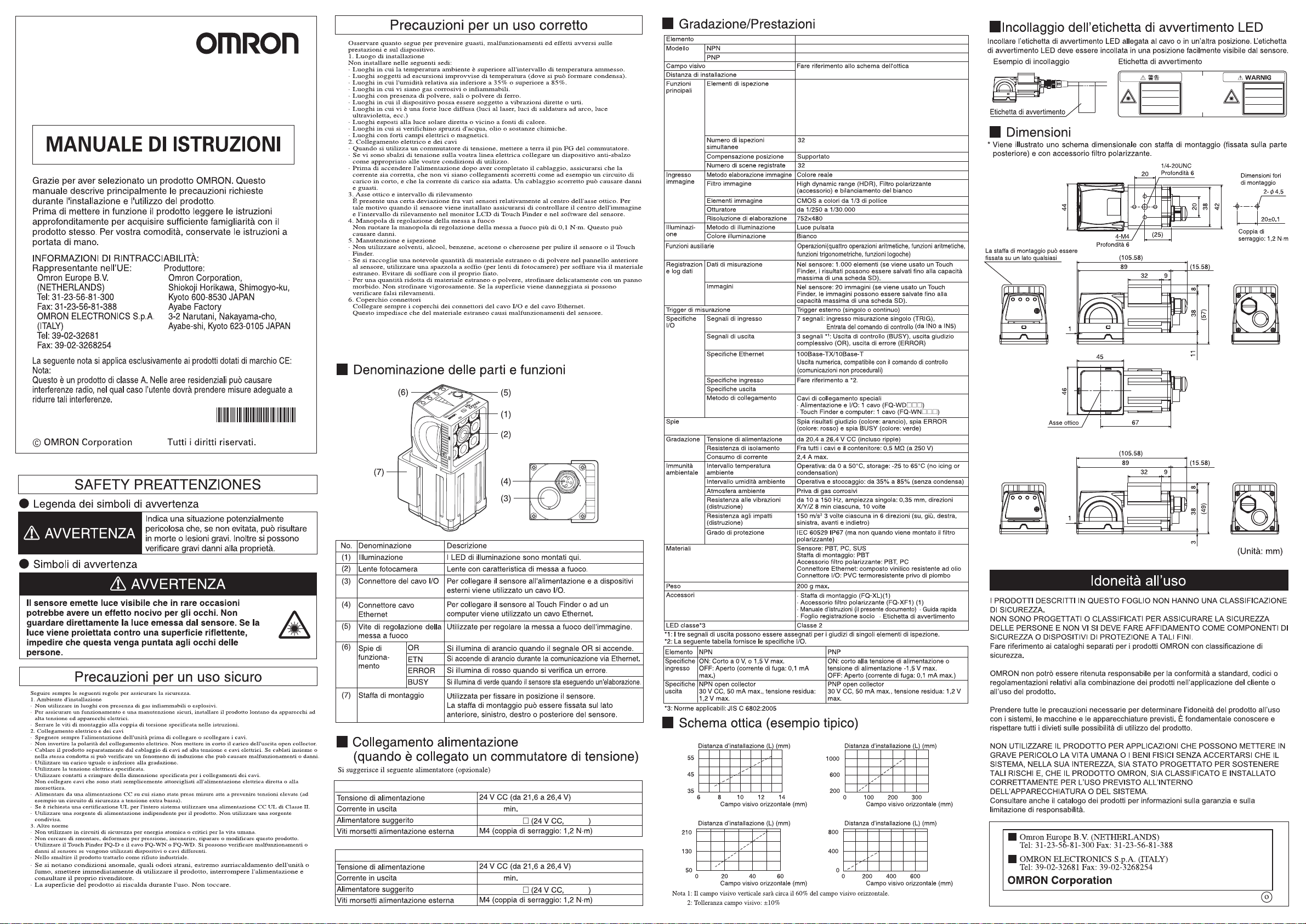
■Dimensions
Always follow the rules below to ensure safety.
1. Installation environment
· Do not use in a location where there is ammable or explosive gas.
· To ensure safe operation and maintenance, install away from high-voltage equipment and
power equipment.
· Tighten the mounting screws to the torque specied in these instructions.
2. Power and cable connections
· Always turn off the power of the unit before connecting or disconnecting cables.
· Do not reverse the polarity of the power connection. Do not short the load of the open
collector output.
·
Wire this product separately from the wiring of high-voltage wires and power wires. If wired
together or in the same conduit, induction may occur and cause malfunctioning or damage.
· Use a load that is equal to or less than the rating.
· Use the specied power voltage.
· Use the specied size of crimp terminals for wiring connections. Do not connect wires that
have been simply twisted together directly to the power supply or terminal block.
· Supply power from a DC power supply for which measures have been applied to prevent
high voltages (e.g., a safety extra low voltage circuit).
· If UL certication is required for the overall system, use a UL Class II DC power supply.
· Use an independent power source for this product. Do not use a shared power source.
3. Other Rules
· Do not use in safety circuits for atomic energy or that are critical for human life.
· Do not attempt to disassemble, deform by pressure, incinerate, repair, or modify this product.
· Use the FQ-D Touch Finder and the FQ-WN or FQ-WD Cable. Sensor malfunction or
damage may occur if any other devices or cables are used.
· When disposing of the product, treat as industrial waste.
· If you notice an abnormal condition such as a strange odor, extreme heating of the unit, or
smoke, immediately stop using the product, turn off the power, and consult your dealer.
· The device surface becomes hot during use. Do not touch.
Observe the following to prevent failure, malfunctioning, and adverse effects on performance and
the device.
1. Installation site
· Do not install in the following locations:
· Locations where the ambient temperature exceeds the rated temperature range.
· Locations subject to sudden temperature changes (where condensation will form).
· Locations where the relative humidity is below or above 35 to 85% RH.
· Locations where there are corrosive or ammable gases.
· Locations where there is dust, salt, or iron powder.
· Locations where the device will be subject to direct vibration or shock.
· Locations where there is strong scattered light (laser light, arc welding light, ultraviolet light, etc.)
· Locations exposed to direct sunlight or next to a heater.
· Locations where there is splashing or spraying of water, oil, or chemicals.
· Locations where there is a strong electrical or magnetic eld.
2. Power and cable connections
· When using a switching regulator, ground the FG pin of the switching regulator.
·
If there are surges on your power line, connect a surge absorber as appropriate for your conditions of use.
· Before turning on the power after the wiring is completed, verify that the power is correct, that
there are no incorrect connections such as a shorted load circuit, and that the load current is
suitable. Incorrect wiring may cause damage and failures.
3. Optical axis and detection range
There is a certain amount of deviation among sensors in the center of the optical axis. For this
reason, when installing the sensor, be sure to check the center of the image and the detection
range in the LCD monitor of the Touch Finder and in the sensor software.
4. Focus adjustment knob
Do not turn the focus adjustment knob to higher than 0.1 N·m. This may cause damage.
5. Maintenance and inspection
· Do not use thinner, alcohol, benzene, acetone, or kerosene to clean the sensor or Touch Finder.
·
If considerable foreign matter or dust collects on the panel on the front of the senor, use a blower
brush (for camera lenses) to blow off the foreign matter. Avoid blowing it off with your breath.
· For a small amount of foreign matter or dust, gently wipe with a soft cloth. Do not wipe hard.
If the surface is damaged, false detection may result.
6. Connector cover
Always attach the covers of I/O cable connector and Ethernet cable connector.
This prevents extraneous material from making malfunction of sensor.
7. Defective pixel
· It is neither a defect of the product nor a breakdown though two or more defective pixels might
beincluded in this product by the specication of CMOS image sensor.
8. Installation of camera
· In the environment with high humidity and intense temperature change, the inside of a front
plate might uncommonly become cloudy.
The following power supply is recommended (option)
Note 1: Vertical eld of view will be approximately 60% of the horizontal eld of view.
2: Field of view tolerance: ±10%
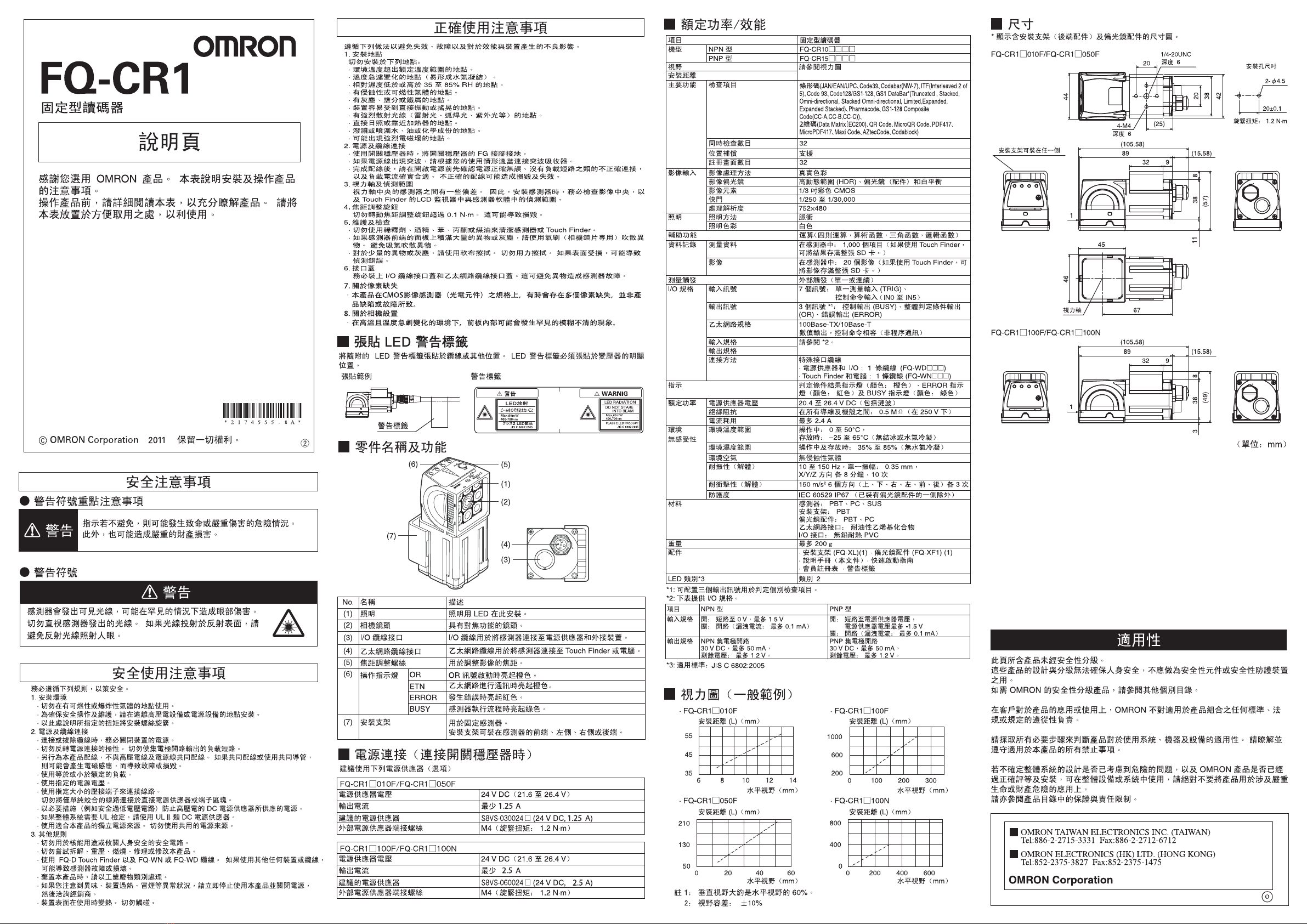
■Part Names and Functions
■Optical diagram (typical example)
■Power connection
(when a switching regulator is connected)
(Unit: mm)
WARNING
WARNING
(2)
(3)
(5)
(1)
(6)
(7)
(4)
FQ-CR1□010F/FQ-CR1□050F
FQ-CR1□100F/FQ-CR1□100N
6 8 10 12 14 0 100 200 300
0 200 400 600
0 20 40 60
50
130
210
Installation distance (L) (mm)
Installation distance (L) (mm)
Installation distance (L) (mm)
Installation distance (L) (mm)
Horizontal field of view (mm)
Horizontal field of view (mm)
Horizontal field of view (mm)
Horizontal field of view (mm)
· FQ-CR1
□
010F · FQ-CR1
□
100F
· FQ-CR1
□
050F · FQ-CR1
□
100N
35
45
55
200
600
1000
400
0
800
DescriptionNameNo.
(1)
(2)
(5)
(3)
(4)
(6)
(7)
Lighting
FQ-CR1□010F/FQ-CR1□050F
24 VDC (21.6 to 26.4 V)
1.25 A min.
S8VS-030024□(24 VDC, 1.25 A)
M4 (tightening torque: 1.2 N・m)
Power supply voltage
Output current
Recommended Power Supply
External power supply terminal screws
FQ-CR1□100F/FQ-CR1□100N
24 VDC (21.6 to 26.4 V)
2.5 A min.
S8VS-060024□(24 VDC, 2.5 A)
M4 (tightening torque: 1.2 N・m)
Power supply voltage
Output current
Recommended Power Supply
External power supply terminal screws
Camera lens
Focus adjustment screw
Mounting Bracket
I/O Cable connector
Ethernet cable
connector
Operation
indicators
LEDs for illumination are mounted here.
Lens with a focus feature.
Used to adjust the focus of the image.
Lights orange when the OR signal turns ON.
Lights orange during communication by Ethernet.
Lights red when an error occurs.
Lights green when the Sensor is executing a process.
An I/O Cable is used to connect the Sensor to the power
supply and external devices.
Used to secure the Sensor in place.
The Mounting Bracket can be attached to the front, left
side, right side, or back of the Sensor.
An Ethernet cable is used to connect the Sensor to the
Touch Finder or a computer.
OR
ETN
ERROR
BUSY
Item
NPN
ON: Shorted to 0 V, or 1.5 V max.
OFF: Open (leakage current: 0.1 mA max.)
NPN open collector
30 VDC, 50 mA max., residual voltage: 1.2
V max.
PNP
ON: Shorted to power supply voltage, or power
supply voltage -1.5 V max.
OFF: Open (leakage current: 0.1 mA max.)
PNP open collector
30 VDC, 50 mA max., residual voltage: 1.2 V
max.
Input
specifica-
tions
Output
specifica-
tions
* Dimension diagram with mounting bracket (rear-side attachment) and polarizing filter
attachment is shown.
■Attaching the LED Warning Label
Attach the enclosed LED warning label to the cable or other location. The LED warning
label must be attached to a location that is readily visible from the Sensor.
*3: Applicable standards: JIS C 6802:2005
*1: The three output signals can be allocated for the judgments of individual inspection items.
*2: The following table gives the I/O specifications.
■
Ratings/Performance
Item
Fixed Mount Multi Code Reader
Refer to the optical diagram
Real color
High dynamic range (HDR) polarizing filter
(attachment), and white balance
FQ-CR10□□□□
FQ-CR15□□□□
Supported
32
32
Field of view
Installation distance
Model NPN
PNP
Inspection items
Position compensation
Number of registered scenes
Image processing method
Image filter
1/3-inch color CMOS
Image elements
1/250 to 1/30,000
752×480
Pulse
White
Shutter
Processing resolution
Lighting method
Lighting color
Number of simultaneous inspections
Main
functions
Image
input
Lighting
Auxiliary Functions Operations(Four arithmetic operations, arithmetic
functions, trigonometric functions, Logic functions)
In Sensor: 1,000 items (If a Touch Finder is used,
results can be saved up to the capacity of an SD card.)
In Sensor: 20 images (If a Touch Finder is used, images
can be saved up to the capacity of an SD card.)
7 signals: Single measurement input (TRIG),
Control Command Input (IN0 to IN5)
Refer to *2.
Measurement trigger
Materials
Accessories
Indications
Weight
LED class*
3
External trigger (single or continuous)
100Base-TX/10Base-T
Numerical output, control command compatible
(Non-procedural communications)
20.4 to 26.4 VDC (including ripple)
2.4 A max.
No corrosive gas
IEC 60529 IP67 (except when the polarizing filter
attachment is attached)
200 g max.
Class 2
Between all lead wires and case: 0.5 MΩ(at 250 V)
Operating: 0 to 50°C, storage: -25 to 65°C (no icing or condensation)
Operating and storage: 35% to 85% (with no condensation)
Input specifications
Output specifications
Power supply voltage
Insulation resistance
Current consumption
Degree of protection
Ambient atmosphere
10 to 150 Hz, single amplitude: 0.35 mm, X/Y/Z
directions 8 min each, 10 times
Vibration resistance
(destruction)
150 m/s
2
3 times each in 6 direction (up, down, right,
left, forward, and backward)
Sensor: PBT, PC, SUS
Mounting Bracket: PBT
Polarizing Filter Attachment: PBT, PC
Ethernet connector: Oil-resistance vinyl compound
I/O connector: Lead-free heat-resistant PVC
· Mounting Bracket (FQ-XL)(1)
· Polarizing Filter Attachment (FQ-XF1) (1)
· Instruction Manual (this document) · Quick Startup Guide
· Member Registration Sheet · Warning Label
Shock resistance
(destruction)
Ambient temperature range
Ambient humidity range
Ethernet specifications
Images
Input signals
3 signals *1: Control output (BUSY), overall judgment
output (OR), error output (ERROR)
Judgment results indicator (color: orange), ERROR
indicator (color: red), and BUSY indicator (color: green)
Special connector cables
-
Power supply and I/O: 1cable (FQ-WD□□□)
-
Touch Finder and computer: 1cable (FQ-WN□□□)
Output signals
Connection method
Measurement dataData
logging
Ratings
Environ-
mental
immunity
I/O
specifications
The mounting bracket can be
attached to any side
Mounting hole
dimensions
Tightening
torque: 1.2 N·m
38
11
1
(57)
8
46
45
32
89
(105.58)
(15.58)
9
44
67
20
20
38
42
(25)
383
1
(49)
8
32
89
(105.58)
(15.58)
9
20±0.1
2-4.5Dia.
4-M4
Depth 6
Optical axis
1/4-20UNC
Depth 6
Attachment Example Warning Label
Warning Label
Max.65mW
LED RADIATION
DO NOT STARE
INTO BEAM
CLASS 2 LED PRODUCT
JIS C 6802:2005
JIS C 6802:2005
400-700nm
LED放射
ビームをのぞき込まないこと
ク ラ ス 2 LE D 製 品
Max.65mW
400-700nm
© OMRON Corporation All Rights Reserved.
Fixed Mount Multi Code Reader
FQ-CR1
INSTRUCTION SHEET
Thank you for selecting OMRON product. This sheet pri-
marily describes precautions required in installing and
operating the product.
Before operating the product, read the sheet thoroughly to
acquire sufficient knowledge of the product. For your con-
venience, keep the sheet at your disposal.
The following notice applies only to products that carry the CE mark:
Notice:
This is a class A product. In residential areas it may cause radio
interference, in which case the user may be required to take adequate
measures to reduce interference.
Manufacturer:
Omron Corporation,
Shiokoji Horikawa, Shimogyo-ku,
Kyoto 600-8530 JAPAN
Ayabe Factory
3-2 Narutani, Nakayama-cho,
Ayabe-shi, Kyoto 623-0105 JAPAN
TRACEABILITY INFORMATION:
Representative in EU:
Omron Europe B.V.
Wegalaan 67-69
2132 JD Hoofddorp,
The Netherlands
Model
2011
Bar code (JAN/EAN/UPC, Code39, Codabar (NW-7), ITF (Interleaved
2 of 5), Code 93, Code128/GS1-128, GS1 DataBar* (Truncated,
Stacked, Omni-directional, Stacked Omni-directional, Limited,
Expanded, Expanded Stacked), Pharmacode, GS1-128 Composite
Code (CC-A, CC-B, CC-C)),
2D code (Data Matrix (EC200), QR Code, MicroQR Code, PDF417,
MicroPDF417, Maxi Code, AZtecCode, Codablock)
OMRON Corporation
Suitability for Use
EUROPE
OMRON EUROPE B.V. Sensor Business Unit
Carl-Benz Str.4, D-71154 Nufringen Germany
Phone:49-7032-811-0 Fax: 49-7032-811-199
NORTH AMERICA
OMRON ELECTRONICS LLC
One Commerce Drive Schaumburg,IL 60173-5302 U.S.A.
Phone:1-847-843-7900 Fax : 1-847-843-7787
ASIA-PACIFIC
OMRON ASIA PACIFIC PTE. LTD.
No. 438A Alexandra Road #05-05-08(Lobby 2),
Alexandra Technopark, Singapore 119967
Phone : 65-6835-3011 Fax :65-6835-2711
o
THE PRODUCTS CONTAINED IN THIS SHEET ARE NOT SAFETY RATED.
THEY ARE NOT DESIGNED OR RATED FOR ENSURING SAFETY OF
PERSONS, AND SHOULD NOT BE RELIED UPON AS A SAFETY
COMPONENT OR PROTECTIVE DEVICE FOR SUCH PURPOSES.
Please refer to separate catalogs for OMRON's safety rated products.
OMRON shall not be responsible for conformity with any standards, codes, or
regulations that apply to the combination of the products in the customer's
application or use of the product.
Take all necessary steps to determine the suitability of the product for the
systems, machines, and equipment with which it will be used.
Know and observe all prohibitions of use applicable to this product.
NEVER USE THE PRODUCTS FOR AN APPLICATION INVOLVING
SERIOUS RISK TO LIFE OR PROPERTY WITHOUT ENSURING THAT THE
SYSTEM AS A WHOLE HAS BEEN DESIGNED TO ADDRESS THE RISKS,
AND THAT THE OMRON PRODUCT IS PROPERLY RATED AND
INSTALLED FOR THE INTENDED USE WITHIN THE OVERALL
EQUIPMENT OR SYSTEM.
See also Product catalog for Warranty and Limitation of Liability.
CHINA
OMRON(CHINA) CO., LTD.
Room 2211, Bank of China Tower,
200 Yin Cheng Zhong Road,
PuDong New Area, Shanghai, 200120, China
Phone : 86-21-5037-2222 Fax :86-21-5037-2200
OCT, 2009
D