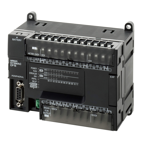
Omron CP1L User manual

1CPU Units and Expansion Units
CP1L
CPU Units and Expansion Units
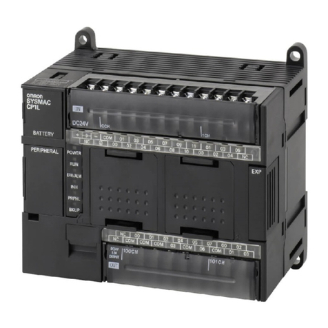
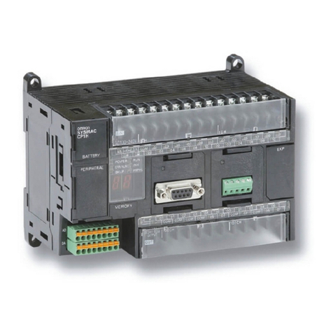
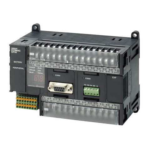
When it comes to controllers for compact machines,
Omron's new CP1L series offers the compactness of
a micro-PLC with the capability of a modular PLC.
But this new and exciting range is not only compact, it
is scaleable, has a faster processing speed than other
controllers and is in a class of its own when it comes
to price/performance. Naturally, it is compatible with
all other devices in the Omron PLC line up.
• 4 high-speed encoder inputs and 2 high-speed
pulse outputs
• CPUs with AC or DC supply and 10, 14, 20, 30, 40
or 60 I/O built-in
• Instruction set compatible with CP1H-, CJ1-,
and CS1 series PLC
• Optional RS232C and RS-422A/485 serial ports
• USB programming port
• Scaleable with a wide range of I/O units
(maximum up to 180 I/O points)
• Motion functionality
• One and the same software as other Omron
controllers
CPU Units
CPU Unit Specification
Type CP1L-M60
(60 points)
CP1L-M40
(40 points)
CP1L-M30
(30 points)
CP1L-L20
(20 points)
CP1L-L14
(14 points)
CP1L-L10
(10 points)
Item Models CP1L-M60@@-@CP1L-M40@@-@CP1L-M30@@-@CP1L-L20@@-@CP1L-L14@@-@CP1L-L10@@-@
Control method Stored program method
I/O control method Cyclic scan with immediate refreshing
Program language Ladder diagram
Function blocks Maximum number of function block definitions: 128 Maximum number of instances: 256
Languages usable in function block definitions: Ladder diagrams, structured text (ST)
Function blocks cannot be used in CP1L-J CPU Unit.
Instruction length 1 to 7 steps per instruction
Instructions Approx. 500 (function codes: 3 digits)
Instruction execution time Basic instructions: 0.61 µs min. Special instructions: 4.1 µs min.
Common processing time 0.38 ms
Program capacity 10K steps 5Ksteps (J models: 1K steps)
Number of tasks 288 (32 cyclic tasks and 256 interrupt tasks)
Scheduled
interrupt tasks
1 (interrupt task No. 2, fixed)
Input
interrupt
tasks
6 (interrupt task No. 140 to 145, fixed) 4 (interrupt task No.
140 to 143, fixed)
2 (interrupt tasks No.
140 to 141, fixed)
(Interrupt tasks can also be specified and executed for high-speed counter interrupts and executed.)
Maximum subroutine number 256
Maximum jump number 256
I/O
areas
Input bits 36: CIO 0.00 to CIO
0.11 and CIO 1.00 to
CIO 1.11 and CIO
2.00 to CIO 2.11
24: CIO 0.00 to CIO
0.11 and CIO 1.00 to
CIO 1.11
18: CIO 0.00 to CIO
0.11 and CIO 1.00 to
CIO 1.05
12: CIO 0.00 to CIO
0.11
8: CIO 0.00 to CIO
0.07
6: CIO 0.00 to CIO
0.05
Output bits 24: CIO 100.00 to
CIO 100.07 and CIO
101.00 to CIO 101.07
and CIO 102.00 to
CIO 102.07
16: CIO 100.00 to
CIO 100.07 and
CIO 101.00 to CIO
101.07
12: CIO 100.00 to
CIO 100.07 and CIO
101.00 to CIO 101.03
8: CIO 100.00 to CIO
100.07
6: CIO 100.00 to CIO
100.05
4: CIO 100.00 to CIO
100.03
1:1 Link Area
1,024 bits (64 words): CIO 3000.00 to CIO 3063.15 (CIO 3000 to CIO 3063) -
Serial PLC
Link Area
1,440 bits (90 words): CIO 3100.00 to CIO 3189.15 (CIO 3100 to CIO 3189) -
Work bits 8,192 bits (512 words): W000.00 to W511.15 (W0 to W511)
CIO Area: 37,504 bits (2,344 words): CIO 3800.00 to CIO 6143.15 (CIO 3800 to CIO 6143)
TR Area 16 bits: TR0 to TR15
Holding Area 8,192 bits (512 words): H0.00 to H511.15 (H0 to H511)
AR Area Read-only (Write-prohibited): 7168 bits (448 words): A0.00 to A447.15 (A0 to A447)
Read/Write: 8192 bits (512 words): A448.00 to A959.15 (A448 to A959)

2Expansion Units
Timers 4,096 bits: T0 to T4095
Counters 4,096 bits: C0 to C4095
DM Area
32 Kwords: D0 to D32767 10 Kwords: D0 to D9999, D32000 to D32767
Data Register Area 16 registers (16 bits): DR0 to DR15
Index Register Area 16 registers (32 bits): IR0 to IR15
Task Flag Area 32 flags (32 bits): TK0000 to TK0031
Trace Memory 4,000 words (500 samples for the trace data maximum of 31 bits and 6 words.)
Memory Cassette A special Memory Cassette (CP1W-ME05M) can be mounted. Note: Can be used for program backups and auto-booting.
Clock function Supported. Accuracy (monthly deviation): -4.5 min to -0.5 min (ambient temperature: 55°C),
-2.0 min to +2.0 min (ambient temperature: 25°C), -2.5 min to +1.5 min (ambient temperature: 0°C)
Communications functions One built-in peripheral port (USB 1.1): For connecting Support Software only.
A maximum of two Serial Communications Option Boards
can be mounted.
A maximum of one Serial Communications
Option Board can be mounted. -
Memory backup Flash memory: User programs, parameters (such as the PLC Setup), comment data, and the entire DM Area can be saved
to flash memory as initial values.
Battery backup: The Holding Area, DM Area, and counter values (flags, PV) are backed up by a battery.
Battery service life 5 years at 25°C. (Use the replacement battery within two years of manufacture.)
Built-in input terminals 60 terminals (36
inputs, 24 outputs)
40 (24 inputs,
16 outputs)
30 (18 inputs,
12 outputs)
20 (12 inputs,
8 outputs)
14 (8 inputs,
6 outputs)
10 (6 inputs,
4 outputs)
Number of connectable
Expansion Units and
Expansion I/O Units
CP-series Expansion Unit and Expansion I/O Units: 3 max. CP-series Expansion Units and Expansion
I/O Units: 1 max. -
Max. number of I/O points 180 (60 built in
+ 40 per Expansion
(I/O) Unit x 3 units)
160 (40 built in
+ 40 per Expansion
(I/O) Unit x 3 units)
150 (30 built in
+ 40 per Expansion
(I/O) Unit ×3 Units)
60 (20 built in
+ 40 per Expansion
(I/O) Unit ×1 Unit)
54 (14 built in
+ 40 per Expansion
(I/O) Unit ×1 Unit)
10
Interrupt inputs 6 inputs (Response time: 0.3 ms) 4 inputs
(Response time:
0.3 ms)
2 inputs
(Response time:
0.3 ms)
Interrupt inputs counter mode 6 inputs (Response frequency: 5 kHz max. for all interrupt inputs), 16 bits
Up or down counters
4 inputs (Response
frequency:
5 kHz max. for all
interrupt inputs),
16 bits
Up or down counters
2 inputs (Response
frequency:
5 kHz max. for all
interrupt inputs),
16 bits
Up or down counters
Quick-response inputs 6 points (Min. input pulse width: 50 µs) 4 points (Min. input
pulse width: 50 µs)
2 points (Min. input
pulse width: 50 µs)
Scheduled interrupts 1
High-speed counters 4 counters, 2 axes (24-VDC input) 4 inputs: Differential phases (4x), 50 kHz or Single-phase (pulse plus direction, up/down,
increment), 100 kHz
Value range: 32 bits, Linear mode or ring mode
Interrupts: Target value comparison or range comparison
Pulse outputs
(models with
transistor
outputs only)
Pulse outputs
Trapezoidal or S-curve acceleration and deceleration (Duty ratio: 50% fixed)
2 outputs, 1 Hz to 100 kHz (CCW/CW or pulse plus direction)
PWM outputs Duty ratio: 0.0% to 100.0% (specified in increments of 0.1% or 1%)
2 outputs, 0.1 to 6553.5 Hz or 1 to 32,800 Hz (Accuracy: ±5% at 1 kHz)
Analog control 1 (Setting range: 0 to 255)
External analog input 1 input (Resolution: 1/256, Input range: 0 to 10 V). Not isolated.
Type CP1L-M60
(60 points)
CP1L-M40
(40 points)
CP1L-M30
(30 points)
CP1L-L20
(20 points)
CP1L-L14
(14 points)
CP1L-L10
(10 points)
Item Models CP1L-M60@@-@CP1L-M40@@-@CP1L-M30@@-@CP1L-L20@@-@CP1L-L14@@-@CP1L-L10@@-@

CPU Units and Expansion Units 3
CP1L CPU Units with 60 I/O Points
CP1L CPU Units with 40 I/O Points
CP1L CPU Units with 30 I/O Points
CP1L CPU Units with 14 or 20 I/O Points
CP1L CPU Units with 10 I/O Points
Expansion Units and Expansion I/O Units
Dimensions (Unit: mm)
8
85
195
185
110
100
90
Four, 4.5 dia.
90100110
140
150
8
85
Four, 4.5 dia.
90100110
120
130
8
85
Four, 4.5 dia.
90100110
76
86
8
85
Four, 4.5 dia.
66
56
110
100
90
Two, 4.5 dia.
85
8
50
66
90
IN
00 02
01COM 03
COM 05 07
04 06
CH 00 01 02 03
08 0910 11
8ED
EXP
IN
00
CH
CH
02 04 06 08 10
OUT
01COM 03 05 07 0911
COM COM COM 03 COM 06
00 01 02 04 05 07
00 01 02 03 04 05 06 07
08 0910 11
20EDR1
CH 00 01 02 03 04 05 06 07
NC
NC
NC
CH
EXP
50
86
90
150
140
110
100
90
8
50
COMCOMCOMCOMCOM
NC
05
COM
05
COM
‚n‚t‚s
NC
EXP
32ER
CH
CH
07
0604
02
03
01
00
07
06
040302
01
COMCOMCOM COM
NC
00
01
00
CHCH
NCNCNC
NCNCNC
060403
0705
0207
01
00
0604
05
0302
COM
‚b‚g
‚b‚g
‚b‚g
‚b‚g
‚O‚O
‚O‚P
‚O‚Q ‚O‚R ‚O‚S‚O‚T ‚O‚U ‚O‚V
‚O‚O
‚O‚P
‚O‚Q ‚O‚R ‚O‚S‚O‚T ‚O‚U ‚O‚V
‚O‚O
‚O‚P
‚O‚Q ‚O‚R ‚O‚S‚O‚T ‚O‚U ‚O‚V
‚O‚O
‚O‚P
‚O‚Q ‚O‚R ‚O‚S‚O‚T ‚O‚U ‚O‚V
Four Ø4.5 holes
CP1W-20ED@
CP1W-16ER
CP1W-AD041/CP1W-DA041
CP1W-MAD11/CP1W-TS@@@
CP1W-8E@@
CP1W-SRT21
CP1W-32ER/32ET/32ET1
CH
NC
NC
NC
NC
NC
NC
COM
COM COM COM COM COM COM03 06 01 03 06
00 02 04 06 08 10
00 01 02 04 05 07 00 02 04 05 07
00 02 04 06 08 10
01 03 05 07 0911 01 03 05 07 0911
IN
40EDR
OUT
CH CH
CH CH
EXP
CH
CH
CH
111009080706050403020100
111009080706050403020100
0706050403020100
0706050403020100
Four,
4.5 dia. 8
50
110
100
90
140
150
CP1W-40ED@

4Expansion Units
CP1L CPU Units
Options for CPU Units
Programming Devices
Ordering Information
CPU Unit Specifications Model Standards
Power
supply
Output method Inputs Outputs
CP1L-M CPU Units with 60
Points
AC power
supply
Relay output 36 24 CP1L-M60DR-A UC1, N, L,
CE
DC power
supply
CP1L-M60DR-D
Transistor output
(sinking)
CP1L-M60-DT-D
Transistor output
(sourcing)
CP1L-M60-DT1-D
CP1L-M CPU Units with 40 Points AC power
supply
Relay output 24 16 CP1L-M40DR-A
DC power
supply
CP1L-M40DR-D
Transistor output
(sinking)
CP1L-M40DT-D
Transistor output
(sourcing)
CP1L-M40DT1-D
CP1L-M CPU Units with 30 Points AC power
supply
Relay output 18 12 CP1L-M30DR-A
DC power
supply
CP1L-M30DR-D
Transistor output
(sinking)
CP1L-M30DT-D
Transistor output
(sourcing)
CP1L-M30DT1-D
CP1L-L CPU Units with 20 Points AC power
supply
Relay output 12 8 CP1L-L20DR-A
DC power
supply
CP1L-L20DR-D
Transistor output
(sinking)
CP1L-L20DT-D
Transistor output
(sourcing)
CP1L-L20DT1-D
CP1L-L CPU Units with 14 Points AC power
supply
Relay output 8 6 CP1L-L14DR-A
DC power
supply
CP1L-L14DR-D
Transistor output
(sinking)
CP1L-L14DT-D
Transistor output
(sourcing)
CP1L-L14DT1-D
CP1L-L CPU Units with 10 Points AC power
supply
Relay output 6 4 CP1L-L10DR-A
DC power
supply
CP1L-L10DR-D
Transistor output
(sinking)
CP1L-L10-DT-D
Transistor output
(sourcing)
CP1L-L10-DT1-D
Name Specifications Model Standards
RS-232C Option Board For CPU Unit option port. CP1W-CIF01 UC1, N, L,
CE
RS-422A/485 Option Board For CPU Unit option port. CP1W-CIF11
Memory Cassette Can be used for backing up programs or auto-booting. CP1W-ME05M
LCD Option Board Used to monitor and change user-specified messages, time or
other data of the CPU Unit.
CP1W-DAM01
Name Specifications Model Standards
CX-One FA Integrated Tool
Package Ver. 2.0
CX-One is a package that integrates the Support Software for
OMRON PLCs and components. CX-One runs on the following
OS.
OS:Windows 98SE, Me, NT 4.0 (Service Pack 6a), 2000 (Service
Pack 3 or higher), or XP
*CX-Thermo runs only on Windows 2000 (Service Pack 3 or
higher) or XP.
CX-One Ver. 2.0 includes CX-Programmer Ver. 7.@.
For details, refer to the CX-One catalog (Cat. No. R134).
*The software is provided on CDs for the CXONE-AL@@C-@EV2
and on DVD for the CXONE-AL@@D-@EV2.
*Site licenses are available for users who must run the CX-One
on many computers. Ask your OMRON representative for details.
1 license CXONE-AL01C-EV2
CXONE-AL01D-EV2
---
3 licenses CXONE-AL03C-EV2
CXONE-AL03D-EV2
10 licenses CXONE-AL10C-EV2
CXONE-AL10D-EV2
50 licenses CXONE-AL50C-EV2
CXONE-AL50D-EV2
USB Programming cable A-type male to B-type male (Length: 1.8 m) CP1W-CN221 ---

CPU Units and Expansion Units 5
Note: 1. Cannot be used with a peripheral USB port.
2. CP1L PLCs are supported by CX-Programmer version 7.1 or higher.
Expansion Units
Optional Products, Maintenance Products and DIN Track Accessories
Programming Device
Connecting Cable for
CP1W-CIF01 RS-232C
Option Board
Connects DOS computers, D-Sub 9-pin (Length: 2.0 m) For anti-static
connectors
XW2Z-200S-CV ---
Connects DOS computers, D-Sub 9-pin (Length: 5.0 m) XW2Z-500S-CV
Connects DOS computers, D-Sub 9-pin (Length: 2.0 m) XW2Z-200S-V
Connects DOS computers, D-Sub 9-pin (Length: 5.0 m) XW2Z-500S-V
USB-Serial Conversion
Cable
(See note)
USB-RS-232C Conversion Cable (Length: 0.5 m) and PC driver (on a CD-ROM disc) are
included.
Complies with USB Specification 1.1
On personal computer side: USB (A plug connector, male)
On PLC side: RS-232C (D-sub 9-pin, male)
Driver: Supported by Windows 98, Me, 2000, and XP
CS1W-CIF31
Name Output method Inputs Outputs Model Standards
Expansion I/O
Units
Relay 24 16 CP1W-40EDR N, L, CE
Transistor (sinking) CP1W-40EDT
Transistor output (sourcing) CP1W-40EDT1
Relay --- 32 CP1W-32ER U, C, L, CE
Transistor (sinking) CP1W-32ET
Transistor output (sourcing) CP1W-32ET1
Relay 12 8 CP1W-20EDR1
Transistor (sinking) CP1W-20EDT U, C, N, L, CE
Transistor output (sourcing) CP1W-20EDT1
Relay --- 16 CP1W-16ER CE
--- 8 --- CP1W-8ED U, C, N, L, CE
Relay --- 8 CP1W-8ER
Transistor (sinking) --- 8 CP1W-8ET
Transistor output (sourcing) CP1W-8ET1
Analog Input Unit Analog (resolution: 1/6000) 4 --- CP1W-AD041 UC1, CE
Analog
Output Unit
Analog (resolution: 1/6000) --- 4 CP1W-DA041 UC1, CE
Analog I/O
Unit
Analog (resolution: 1/6000) 2 1 CP1W-MAD11 U, C, N, CE
CompoBus/S
I/O Link Unit
--- 8
(I/O link input bits)
8
(I/O link input bits)
CP1W-SRT21 U, C, N, L, CE
Temperature
Sensor Unit
2 thermocouple inputs CP1W-TS001 U, C, N, L, CE
4 thermocouple inputs CP1W-TS002
2 platinum resistance thermometer inputs CP1W-TS101
4 platinum resistance thermometer inputs CP1W-TS102
Name Specifications Model Standards
Battery Set For CP1L CPU Units
(Use batteries within two years of manufacture.)
CJ1W-BAT01 CE
DIN Track Length: 0.5 m; Height: 7.3 mm PFP-50N ---
Length: 1 m; Height: 7.3 mm PFP-100N
Length: 1 m; Height: 16 mm PFP-100N2
End Plate There are 2 stoppers provided with CPU Units and I/O Interface Units as
standard accessories to secure the Units on the DIN Track.
PFP-M
Name Specifications Model Standards

6Expansion Units
UNITED KINGDOM
Omron Electronics Ltd
Opal Drive, Fox Milne, Milton Keynes, MK15 0DG, UK
Tel: +44 (0) 870 752 08 61
Fax: +44 (0) 870 752 08 62
www.omron.co.uk
Austria
Tel: +43 (0) 2236 377 800
www.omron.at
Belgium
Tel: +32 (0) 2 466 24 80
www.omron.be
Czech Republic
Tel: +420 234 602 602
www.omron-industrial.cz
Denmark
Tel: +45 43 44 00 11
www.omron.dk
Finland
Tel: +358 (0) 207 464 200
www.omron.fi
France
Tel: +33 (0) 1 56 63 70 00
www.omron.fr
Germany
Tel: +49 (0) 2173 680 00
www.omron.de
Hungary
Tel: +36 1 399 30 50
www.omron.hu
Italy
Tel: +39 02 326 81
www.omron.it
Netherlands
Tel: +31 (0) 23 568 11 00
www.omron.nl
Norway
Tel: +47 (0) 22 65 75 00
www.omron.no
Poland
Tel: +48 (0) 22 645 78 60
www.omron.pl
Portugal
Tel: +351 21 942 94 00
www.omron.pt
Russia
Tel: +7 495 648 94 50
www.omron-industrial.ru
Spain
Tel: +34 913 777 900
www.omron.es
Sweden
Tel: +46 (0) 8 632 35 00
www.omron.se
Switzerland
Tel: +41 (0) 41 748 13 13
www.omron.ch
Turkey
Tel: +90 (0) 216 474 00 40
www.omron.com.tr
Middle East & Africa
Tel: +31 (0) 23 568 11 00
www.omron-industrial.com
More Omron representatives
www.omron-industrial.com
OMRON EUROPE B.V.
Wegalaan 67-69, NL-2132 JD, Hoofddorp, The Netherlands. Tel: +31 (0) 23 568 13 00 Fax: +31 (0) 23 568 13 88 www.omron-industrial.com
Cat.No. P20E-EN-02 Inlay
Other manuals for CP1L
2
This manual suits for next models
5
Table of contents
Other Omron Computer Hardware manuals

Omron
Omron 3G8F5-DRM21-E - V2 User manual

Omron
Omron GRT1-PNT User manual

Omron
Omron CJ Series Instruction Manual

Omron
Omron G3RV User manual

Omron
Omron SYSMAC C20P User manual

Omron
Omron G3NA User manual
Omron
Omron CS1D DUPLEX SYSTEM - 10-2009 User manual
Omron
Omron CJ2H-CPU64 - User manual

Omron
Omron CP1L CPU UNIT - 03-2009 User manual
Omron
Omron K3TC User manual