FH-SMX21R/SCX21R
Model
© OMRON Corporation 2017 All Rights Reserved.
NOTICE:
This product meets CISPR11 class A. The intended use of this product is in an
industrial environment only.
2.3 W max. (13 VDC)
Instruction Sheet (this sheet), General Compliance Information and Instructions for EU
High speed mode: 5 m max.
Standard mode: Using FZ-VS4: 15 m max.
Using a dedicated product other
than FZ-VS4: 10 m max.
FH-SM21R
FH-SC21R
FH-SC21R FH-SM21R
1-inch
colorCMOS 1-inch
monochromeCMOS
●Performance specifications
5544(H)×3692(V)
2.4(μm)×2.4(μm)
Shuttertype
Rollingshutter
2CH:23.5fps
1CH:12.0fps
Highspeed
mode*1
Frame
rate
2CH:11.1fps
1CH:5.7fps
Standard
mode*1
Numberoflines
toberead
0to20dB
Exposuretime 50μs〜100,000μs
*1ThisSensorhashighspeedmodeandstandardmodeaccordingtoyour
application.Highspeedmodecanbesetinthesystemsettings.
*2Foropticaldiagrams,refertoFHmanualorcatalog.
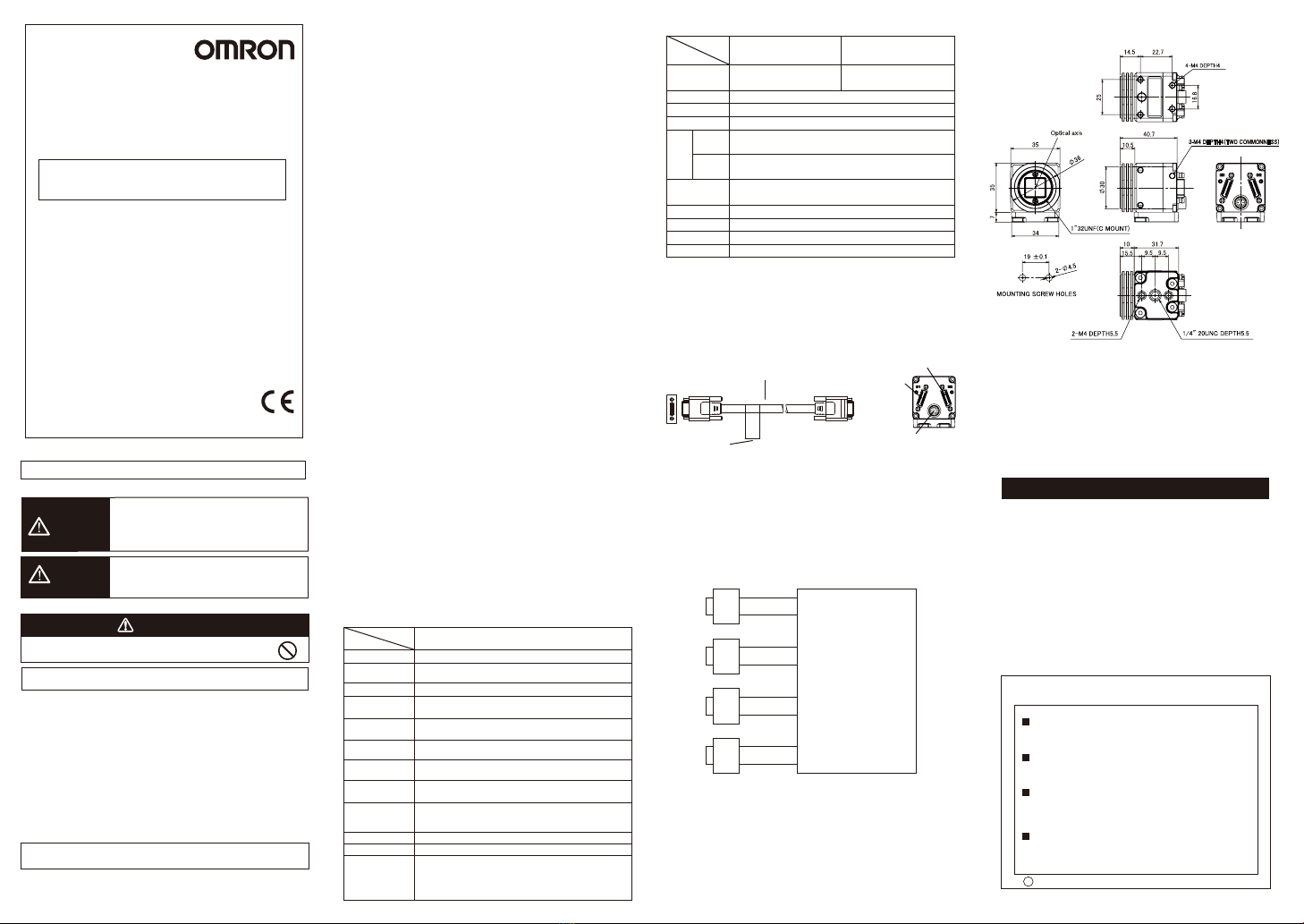
* The base at the bottom of the camera can be mounted to the bottom, top,
and both sides. Remove the base mounting screw (M4x8) and correct the
mounting position. (Recommended mounting screw torque: 1.2 N・m)
Item
Model
10 to 150Hz: half-amplitude: 0.35mm:(maximum acceleration: 50m/s2),
10 times for 8 minutes each in 3 directions
Shock resistance 150m/s2; 3 times each in 6 directions
Operating and storage: 35%RH to 85%RH
(with no condensation)
No corrosive gases
X, Y : ±0.3mm
θx, θy : ±1.5°
Operating: 0 to 40 ℃(with no icing nor condensation)
Storage: -20 to 65 ℃ (with no icing nor condensation)
Powerconsumption
Vibration
resistance
Shock resistance
Ambient
Temperature
Ambient
humidity
Ambient
environment
Center positional
accuracy of
optical axis
Materials
Accessories
Degree of
protection IEC60529 IP40 (in-panel)
■Ratings / Performance
Case: Aluminum alloy
Camera base: PC/GF
Mount screw: brass
●
General specifications
Cable length
Approx. 85 g(including base)
Weight
Item
Model
Camera cable
FZ-VS□□
Name plate Enhancing connetor
Camera cable
connector CH2
Camera cable
connector CH1
Pictureelement
Effectivepixels
Pixelsize
Videooutput
Gain
Lensmounting*2
Digital8bits
1848linesto3692lines(4lineunits)
Cmount(Recommended3Z4S-LEVS-LLDseries)
■Connecting
Using the Camera cable FZ-VS□□(sold separately), connect the connector
on the back of the camera and the camera connector on Sensor Controller
FH series.
■Dimensions (Unit:mm)
* The camera cable FZ-VS□□ has polarity. Be sure to connect the side
with the name plate on it to the sensor controller.
・
When connecting the product to the Sensor Controller with a single camera
cable, connect the cable to CH1 of the camera cable connector.
・
When connecting the product to the Sensor Controller with two camera
cables, connect it as shown below.
(connecting four Cameras)
CH1
Camera
FH-S□□□
Sensor Controller
FH
Cameraconnector0
Cameraconnector1
Cameraconnector2
Cameraconnector3
Cameraconnector4
Cameraconnector5
Cameraconnector6
Cameraconnector7
CH2
CH1
CH2
CH1
CH2
CH1
CH2
Manufacturer:
Omron Corporation,
Shiokoji Horikawa, Shimogyo-ku,
Kyoto 600-8530 JAPAN
Ayabe Factory
3-2 Narutani, Nakayama-cho,
Ayabe-shi, Kyoto 623-0105 JAPAN
TRACEABILITY INFORMATION:
Representative in EU:
Omron Europe B.V.
Wegalaan 67-69
2132 JD Hoofddorp,
The Netherlands
PRECAUTIONS ON SAFETY
ImageSensorforFH-20.4MegapixelDigitalCamera
INSTRUCTION SHEET
Thank you for selecting OMRON product. This sheet
primarily describes precautions required in installing and
operating the product.
Before operating the product, read the sheet thoroughly to
acquire sufficient knowledge of the product. For your
convenience, keep the sheet at your disposal.
PRECAUTIONS FOR SAFE USE
Besuretorespectfollowingitemsforsafety.
・Tightenallscrewssecurelyduringinstallation.
・DonotconnecttheSensortotheproductsotherthanthededicated
cameracable(FZ-VS□□),sensorcontroller(FH),electronicflash
controller(FL-TCC□□□andFLV-TCC□),electronicflash
(FL-MD□□□MC),extensionunit(FZ-VSJ).IftheSensoris
connectedtonon-dedicatedproductsandturnedthepoweron,the
devicesmaybedamagedandbeheatedtoahightemperature.
・Ifyoususpectanerrorormalfunction,stopusingtheController
immediately,turnOFFthepowersupply,andconsultyourOMRON
representative.
・Donottrytodisassemble,repair,ormodifytheproduct.
・Disposeofcomponentsasindustrialwaste.
・Donotputanimpossiblestressonthecameracablewhenyousetit
up.Thecableisdisconnected,anditbecomesimpossiblemightdoa
normalmeasurement.
PRECAUTIONS FOR CORRECT USE
Donotinstallinthefollowinglocations.
・Locationswheretheambienttemperatureexceedstheratedtemperaturerange.
・Locationssubjecttosuddentemperaturechanges(wherecondensationwillform).
・Locationswheretherearecorrosiveorflammablegases.
・Locationswherethereisdust,salt,orironpowder.
・Locationswherethedevicewillbesubjecttodirectvibrationorshock.
・Locationswherethereisstrongscatteredlight.
・Locationsexposedtodirectsunlight
・Locationswherethereissplashingofwater,oil,orchemicals.
・Locationswherethereisastrongelectricalormagneticfield.
・Locationsclosetohigh-voltagedevicesand/orpowerdevices
2.Cables
・Whenconnectingordisconnectingthecameracableorflashcontrollercable,be
suretoturnoffthesensorcontrollerunitandflashcontroller.
・Donotusethecameracableexceedingthespecifiedlength.
・WhenconnectingtheSensorandtheSensorController(FH)withsinglecamera
cable,connectthecabletoCH1ofthecameraconnector.
・WhenconnectingtheSensorandtheSensorController(FH)withtwocamera
cables,thetypeandlengthofthecameracablemustbematched.
・WhenconnectingtheSensorandtheSensorController(FH)withtwocamera
cables,checktheCHnumbersoftheSensorControllersideandCameraside
beforeconnecting.
・UptothreecameracablescanbeconnectedusingtheextensionunitFZ-VSJ.
BesuretousetherecommendedcameracablewithFZ-VSJ.
・Whenconnectingthecameracable,tightenthecablewiththefixingscrewwith
therecommendedtorque(0.15N・m).Applyingexcessiveforcetothecamera
connectormaycausefailureoftheproduct.
・UsetheferritecoreequivalenttoZCAT2035-0930A(manufacturedbyTDK)at
thecontrollersideofthecameracable.
・ThecameracableFZ-VS□□haspolarity.Besuretoconnectthesidewiththe
nameplateonittothesensorcontroller.
3.Mounting
Thecameracaseisconnectedtothe0Vlineoftheinternalcircuit.Observethe
followingprecautionstopreventnoisefromenteringthecamera.
・Donotgroundthecameraunit.
・
BesuretouseaBaseprovidedwiththeUnitforinstallation.Whenmountinga
base,engageitwiththespecifiedscrew(M4x8)withtherecommendedtorque(1.2
N・m ) .
4.Beam
・Thebeamcentermayvaryforeachcamera.Besuretoconfirmthecenter
positionoftheimageusingthemonitorbeforemounting.Inthenatureofthe
materialsused,thebeamcenterofthisproductmaychangeforthenumberof
pixelsduetochangesinambienttemperature.
5.Maintenance
・Avoidusingthinner,alcohol,benzene,acetoneorkerosenetocleantheproduct.
・Ifthereislargedirtordustattachedtotheimagingelement,blowthemoffwith
blowerbrush(forcameralens).Donotuseyourbreathtoblowthedustoff.
・Whenthelensisnotmounted,besuretoattachtheC-mountcaponthelens
mount.Ifdirtordustisattachedtotheimageelements,falsedetectionor
failuremayoccur.
・Besuretoattachaconnectorcaponunusedconnectorsatthebackofthe
camera.Removingtheconnectorcapmaycauseaforeignmaterialenteringinthe
camera,causingfalseoperationorfailure.
・Donotconnectdevicestotheextensionconnectorotherthanthededicatedones
(FL-MD□□□MC,FL-TCC□□□orFLV-TCC□).
6.Imagingelement
・Inthenatureofimagingelement,linesmayappearinimagesduetomeasurement
conditionsorsensitivities.Thisdoesnotindicatedamalfunction.Althoughthere
maybemultiplefaultypixels,thisdoesnotindicateamalfunction.Besureto
checktheactualimagesbeforeusingit.
Pleaseobservethefollowingprecautionstopreventfailuretooperate,
malfunction,orundesirableeffect.
1.Installationandstorageoftheproduct
WARNING
Indicates a potentially hazardous situation
which, if not avoided, will result in minor or
moderate injury, or may result in serious injury
or death. Additionally there may be significant
property damage.
CAUTION
Indicates a potentially hazardous situation
which, if not avoided, may result in minor or
moderate injury, or property damage.
●Meanings of Alert Symbols
●Alert statements
This product is not designed or rated for ensuring safety of
persons either directly or indirectly. Do not use it for such purpose.
WARNING
Suitability for Use
s
Omron Companies shall not be responsible for conformity with any standards,
codes or regulations which apply to the combination of the Product in the
Buyer’s application or use of the Product. At Buyer’s request, Omron will
provide applicable third party certification documents identifying ratings and
limitations of use which apply to the Product. This information by itself is not
sufficient for a complete determination of the suitability of the Product in
combination with the end product, machine, system, or other application or
use. Buyer shall be solely responsible for determining appropriateness of the
particular Product with respect to Buyer’s application, product or system.
Buyer shall take application responsibility in all cases.
NEVER USE THE PRODUCT FOR AN APPLICATION INVOLVING
SERIOUS RISK TO LIFE OR PROPERTY WITHOUT ENSURING THAT THE
SYSTEM AS A WHOLE HAS BEEN DESIGNED TO ADDRESS THE RISKS,
AND THAT THE OMRON PRODUCT(S) IS PROPERLY RATED AND
INSTALLED FOR THE INTENDED USE WITHIN THE OVERALL
EQUIPMENT OR SYSTEM.
See also Product catalog for Warranty and Limitation of Liability.
Oct, 2014
D
OMRON Corporation Industrial Automation Company
Contact: www.ia.omron.com
Tokyo, JAPAN
OMRON ELECTRONICS LLC
2895 Greenspoint Parkway, Suite 200
Hoffman Estates, IL 60169 U.S.A.
Tel: (1) 847-843-7900/Fax: (1) 847-843-7787
OMRON ASIA PACIFIC PTE. LTD.
No. 438A Alexandra Road # 05-05/08 (Lobby 2),
Alexandra Technopark,
Singapore 119967
Tel: (65) 6835-3011/Fax: (65) 6835-2711
OMRON (CHINA) CO., LTD.
Room 2211, Bank of China Tower,
200 Yin Cheng Zhong Road,
PuDong New Area, Shanghai, 200120, China
Tel: (86) 21-5037-2222/Fax: (86) 21-5037-2200
OMRON EUROPE B.V.
Sensor Business Unit
Carl-Benz-Str. 4, D-71154 Nufringen, Germany
Tel: (49) 7032-811-0/Fax: (49) 7032-811-199
Regional Headquarters


