ImageSensorforFH-2Megapixel/4Megapixel
DigitalCamera
FH-S□02/S□04
INSTRUCTION SHEET
Thank you for selecting OMRON product. This sheet pri-
marily describes precautions required in installing and
operating the product.
Before operating the product, read the sheet thoroughly to
acquire sufficient knowledge of the product. For your con-
venience, keep the sheet at your disposal.
Model
© OMRON Corporation 2013 All Rights Reserved.
NOTICE:
This product meets CISPR11 class A. The intended use of this product is in an
industrial environment only.
2.6 W max. (13 VDC)
Instruction Sheet (this sheet)
High speed mode: 5 m max.
Standard mode: Using FZ-VS2: 15 m max.
Using a dedicated product other
than FZ-VS2: 10 m max.
FH-S□02
FH-S□04
FH-SC02 FH-SM02 FH-SC04 FH-SM04
2/3-inch
colorCMOS 2/3-inch
monochrome
CMOS
1-inch
colorCMOS 1-inch
monochrome
CMOS
●Performance specifications
2040(H)×1088(V) 2040(H)×2048(V)
5.5(μm)×5.5(μm)
Scanningmethod
Progressive
2CH:219fps
1CH:109fps
Highspeed
mode*1
Frame
rate
2CH:118fps
1CH:59fps
2CH:103fps
1CH:51fps
Standard
mode*1
2CH:55fps
1CH:27fps
Synchronization
method Internal
1to5times
Exposuretime 25μs〜100,000μs
*1ThisSensorhashighspeedmodeandstandardmodeaccordingtoyour
application.
Highspeedmodecanbesetinthesystemsettings.
*2Foropticaldiagrams,refertoFHmanualorcatalog.
CH1 CH2
* The base at the bottom of the camera can be mounted to the bottom, top,
and both sides. Remove the base mounting screw (M4x8) and correct the
mounting position. (Recommended mounting screw torque: 1.2 N・m)
Item
Model
10 to 150Hz: half-amplitude: 0.35mm:(maximum acceleration: 50m/s
2
),
10 times for 8 minutes each in 3 directions
Shock resistance 150m/s2; 3 times each in 6 directions
Operating and storage: 35% to 85%
(with no condensation)
No corrosive gases
X, Y : ±0.31mm
∂x, ∂y : ±1.7°
Operating: 0 to 40 ℃(with no icing nor condensation)
Storage: -25 to 65 ℃ (with no icing nor condensation)
Powerconsumption
Vibration
resistance
Shock resistance
Ambient
Temperature
Ambient
humidity
Ambient
environment
Center positional
accuracy of
optical axis
Materials
Accessories
Degree of
protection
IEC60529 IP40 (in-panel)
■Ratings / Performance
Case: Aluminum
Camera base: PC/GF
Mount screw: brass
●
General specifications
Cable length
Approx. 110 g (including base)
Weight
Item
Model
Camera cable
FZ-VS□□
Name plate Enhancing connetor
Camera cable
connector CH2
Camera cable
connector CH1
Pictureelement
Effectivepixels
Pixelsize
Videooutput
Gain
Lensmounting*2
Digital(8bits)
Cmount(RecommendedFH-S□02:3Z4S-LESV-Hseries
FH-S□04:3Z4S-LEVS-H1series)
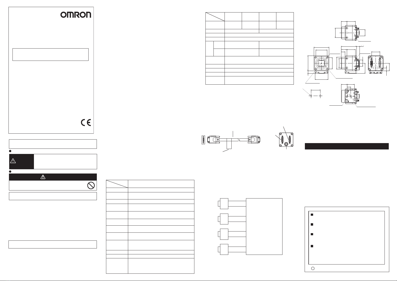
■Connecting
Using the Camera cable FZ-VS□□(sold separately), connect the connector
on the back of the camera and the camera connector on Controller FH series.
■Dimensions (Unit:mm)
OMRON Corporation
Suitability for Use
EUROPE
OMRON EUROPE B.V. Sensor Business Unit
Carl-Benz Str.4, D-71154 Nufringen Germany
Phone:49-7032-811-0 Fax: 49-7032-811-199
NORTH AMERICA
OMRON ELECTRONICS LLC
One Commerce Drive Schaumburg,IL 60173-5302 U.S.A.
Phone:1-847-843-7900 Fax : 1-847-843-7787
ASIA-PACIFIC
OMRON ASIA PACIFIC PTE. LTD.
No. 438A Alexandra Road #05-05-08(Lobby 2),
Alexandra Technopark, Singapore 119967
Phone : 65-6835-3011 Fax :65-6835-2711
p
Omron Companies shall not be responsible for conformity with any
standards, codes or regulations which apply to the combination of the
Product in the Buyer’s application or use of the Product. At Buyer’s request,
Omron will provide applicable third party certification documents identifying
ratings and limitations of use which apply to the Product. This information by
itself is not sufficient for a complete determination of the suitability of the
Product in combination with the end product, machine, system, or other
application or use. Buyer shall be solely responsible for determining
appropriateness of the particular Product with respect to Buyer’s application,
product or system. Buyer shall take application responsibility in all cases.
NEVER USE THE PRODUCT FOR AN APPLICATION INVOLVING SERIOUS
RISK TO LIFE OR PROPERTY OR IN LARGE QUANTITIES WITHOUT
ENSURING THAT THE SYSTEM AS A WHOLE HAS BEEN DESIGNED TO
ADDRESS THE RISKS, AND THAT THE OMRON PRODUCT(S) IS
PROPERLY RATED AND INSTALLED FOR THE INTENDED USE WITHIN THE
OVERALL EQUIPMENT OR SYSTEM.
See also Product catalog for Warranty and Limitation of Liability.
CHINA
OMRON(CHINA) CO., LTD.
Room 2211, Bank of China Tower,
200 Yin Cheng Zhong Road,
PuDong New Area, Shanghai, 200120, China
Phone : 86-21-5037-2222 Fax :86-21-5037-2200
Apr, 2013
D
This product is not designed or rated for ensuring safety
of persons. Do not use it for such purposes.
Meaning of Alert Symbols
Alert statements
WARNING
PRECAUTIONS ON SAFETY
PRECAUTIONS FOR SAFE USE
PRECAUTIONS FOR CORRECT USE
Indicates a potentially hazardous situation which, if
not avoided, will result in minor or moderate injury,
or may result in serious injury or death. Additionally
there may be significant property damage.
WARNING
Besuretorespectfollowingitemsforsafety.
・Tightenallscrewssecurelyduringinstallation.
・DonotconnecttheSensortotheproductsotherthanthededicatedcameracable
(FZ-VS□□),controller(FH),electronicflashcontroller(FL-TCC1andFLV-TCC
□),extensionunit(FZ-VSJ).IftheSensorisconnectedtonon-dedicatedproducts
andturnedthepoweron,thedevicesmaybedamagedandbeheatedtoahigh
temperature.
・Ifyoususpectanerrorormalfunction,stopusingtheControllerimmediately,turn
OFFthepowersupply,andconsultyourOMRONrepresentative.
・Donottrytodisassemble,repair,ormodifytheproduct.
・DisposeofFZ-SCcomponentsasindustrialwaste.
Pleaseobservethefollowingprecautionstopreventfailuretooperate,malfunction,or
undesirableeffect.
1.Installationandstorageoftheproduct
Donotinstallinthefollowinglocations.
・Locationswheretheambienttemperatureexceedstheratedtemperaturerange.
・Locationssubjecttosuddentemperaturechanges(wherecondensationwillform).
* The camera cable FZ-VS□□ has polarity. Be sure to connect the side
with the name plate on it to the controller.
・Locationswheretherearecorrosiveorflammablegases.
・Locationswherethereisdust,salt,orironpowder.
・Locationswherethedevicewillbesubjecttodirectvibrationorshock.
・Locationswherethereisstrongscatteredlight.
・Locationsexposedtodirectsunlight
・Locationswherethereissplashingofwater,oil,orchemicals.
・Locationswherethereisastrongelectricalormagneticfield.
・Locationsclosetohigh-voltagedevicesand/orpowerdevices
2.Cables
・Whenconnectingordisconnectingthecameracableorflashcontrollercable,besure
toturnoffthecontrollerunit.
・Donotusethecameracableexceedingthespecifiedlength.
・WhenconnectingtheSensorandtheController(FH)withsinglecameracable,
connectthecabletoCH1ofthecameraconnector.
・WhenconnectingtheSensorandtheController(FH)withtwocameracables,thetype
andlengthofthecameracablemustbematched.
・WhenconnectingtheSensorandtheController(FH)withtwocameracables,check
theCHnumbersoftheControllersideandCamerasidebeforeconnecting.
・UptothreecameracablescanbeconnectedusingtheextensionunitFZ-VSJ.Be
suretousetherecommendedcameracablewithFZ-VSJ.
・Whenconnectingthecameracable,tightenthecablewiththefixingscrewwiththe
recommendedtorque(0.15N・m).Applyingexcessiveforcetothecameraconnector
maycausefailureoftheproduct.
・UsetheferritecoreequivalenttoZCAT2035-0930A(manufacturedbyTDK)atthe
controllersideofthecameracable.
・ThecameracableFZ-VS□□haspolarity.Besuretoconnectthesidewiththename
plateonittothecontroller.Besuretoconnectthesidewiththenameplateonitto
thecontroller.
3.Mounting
Thecameracaseisconnectedtothe0Vlineoftheinternalcircuit.Observethe
followingprecautionstopreventnoisefromenteringthecamera.
・Donotgroundthecameraunit.
・Besuretouseabaseforinstallation.Whenmountingabase,engageitwiththe
specifiedscrew(M4x8)withtherecommendedtorque(1.2N・m).
・Whensecuringthecamerausingthemountingholeonthelensface(front),besureto
performinsulation.
4.Beam
・Thebeamcentermayvaryforeachcamera.Besuretoconfirmthecenterpositionof
theimageusingthemonitorbeforemounting.Inthenatureofthematerialsused,the
beamcenterofthisproductmaychangeforthenumberofpixelsduetochangesin
ambienttemperature.
5.Maintenance
・Avoidusingthinner,alcohol,benzene,acetoneorkerosenetocleantheproduct.
・Ifthereislargedirtordustattachedtotheimagingelement,blowthemoffwith
blowerbrush(forcameralens).Donotuseyourbreathtoblowthedustoff.
・Whenthelensisnotmounted,besuretoattachtheC-mountcaponthelensmount.If
dirtordustisattachedtotheimageelements,falsedetectionorfailuremayoccur.
・Besuretoattachaconnectorcaponunusedconnectorsatthebackofthecamera.
Removingtheconnectorcapmaycauseaforeignmaterialenteringinthecamera,
causingfalseoperationorfailure.
・Donotconnectdevicestotheextensionconnectorotherthanthededicatedones
(FL-TCC1orFLV-TCC□).
6.Imagingelement
・Inthenatureofimagingelement,linesmayappearinimagesduetomeasurement
conditionsorsensitivities.Thisdoesnotindicatedamalfunction.Althoughtheremay
bemultiplefaultypixels,thisdoesnotindicateamalfunction.Iftheseconditions
affectmeasurementorinspection,usetheCCDcamera.
4-M4DEPTH4
16.8
27
25
Ø32
9.5
14.5 22.7
40.5 8.2
4-M4DEPTH4
30
30
40
407
34 1"-32UNF(CMOUNT)
OPTICALAXIS
4-M4DEPTH4
16.8
25
14.5 22.7
2-M4DEPTH5.5
9.5
19
1/4-20UNCDEPTH5.5
15.5
22.2
(20)
(7.4)
・
When connecting the product to the Controller with a single camera cable,
connect the cable to CH1 of the camera cable connector.
・
When connecting the product to the Controller with two camera cables,
connect it as shown below.
(connecting four Cameras)
CH1
Camera
FH-S□□□
Controller
FH
Cameraconnector0
Cameraconnector1
Cameraconnector2
Cameraconnector3
Cameraconnector4
Cameraconnector5
Cameraconnector6
Cameraconnector7
CH2
CH1
CH2
CH1
CH2
CH1
CH2
2-4.5Dia.
19±0.1
MOUNTINGSCREWHOLES
Manufacturer:
Omron Corporation,
Shiokoji Horikawa, Shimogyo-ku,
Kyoto 600-8530 JAPAN
Ayabe Factory
3-2 Narutani, Nakayama-cho,
Ayabe-shi, Kyoto 623-0105 JAPAN
TRACEABILITY INFORMATION:
Representative in EU:
Omron Europe B.V.
Wegalaan 67-69
2132 JD Hoofddorp,
The Netherlands


