© OMRON Corporation All Rights Reserved.
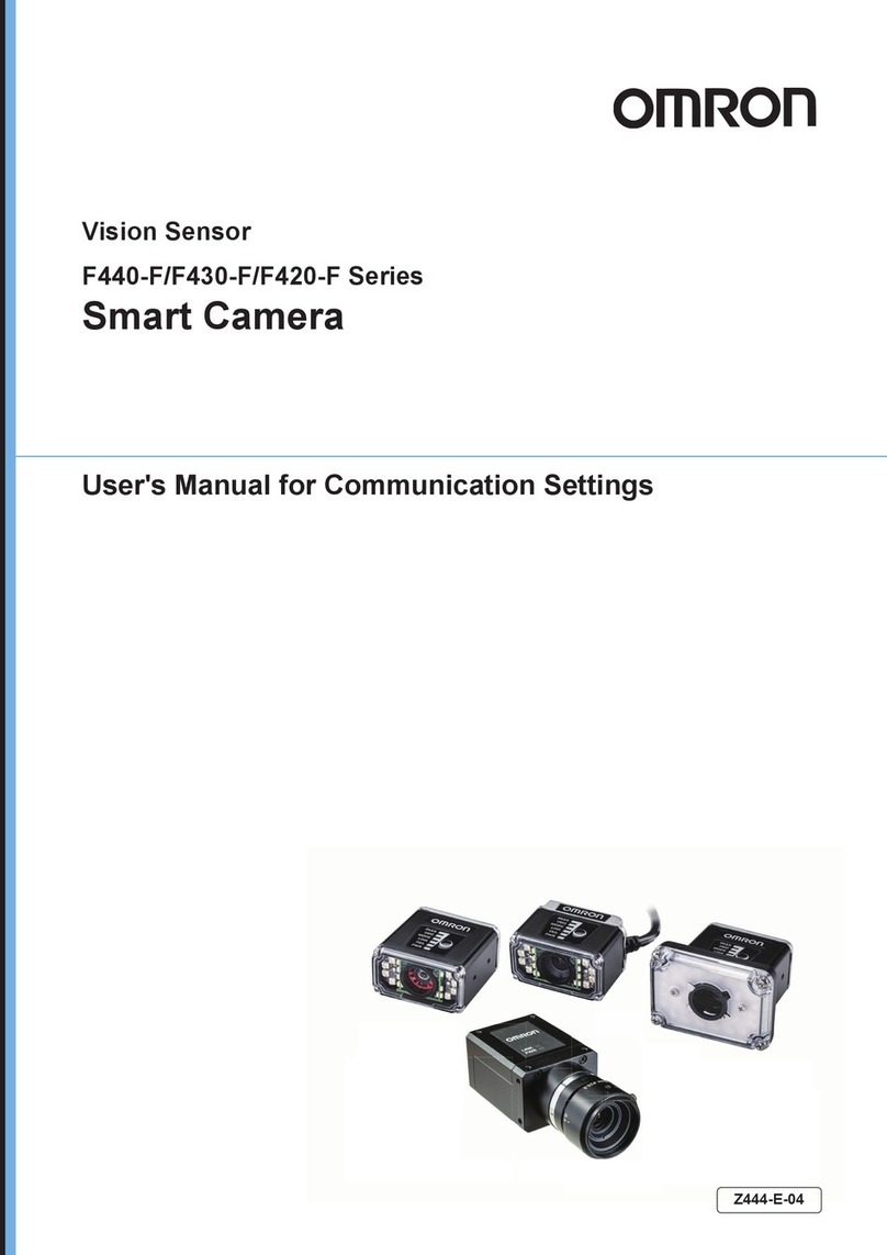
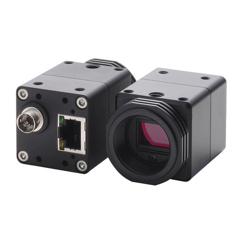
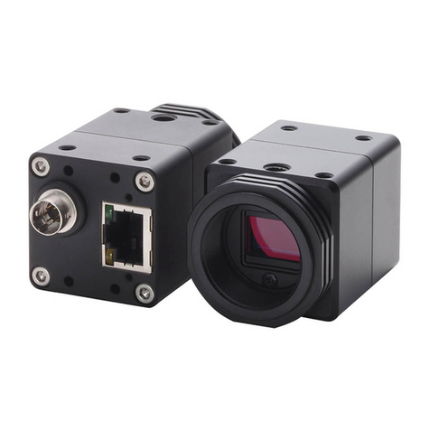
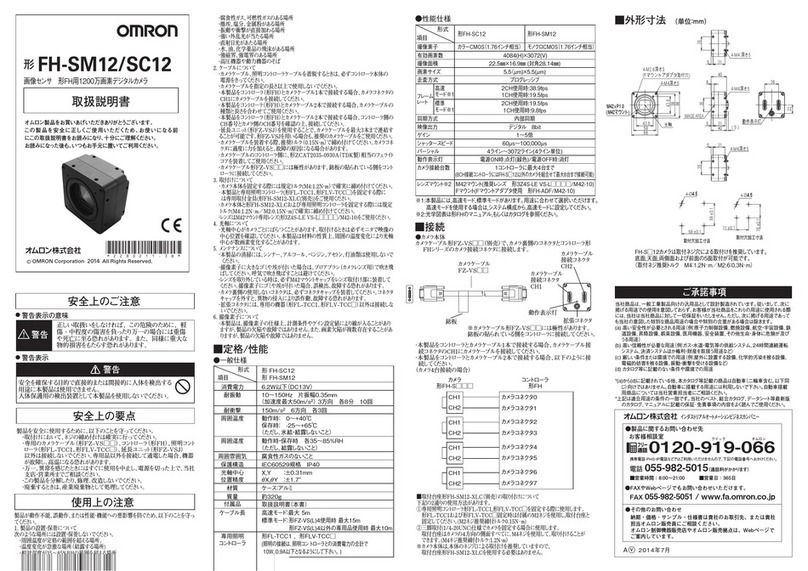
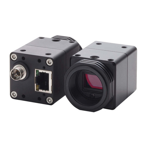
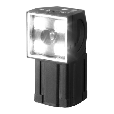
FZ-SFC/SF/SPC/SP
OMRON Corporation
Suitability for Use
EUROPE
OMRON EUROPE B.V. Sensor Business Unit
Carl-Benz Str.4, D-71154 Nufringen Germany
Phone:49-7032-811-0 Fax: 49-7032-811-199
NORTH AMERICA
OMRON ELECTRONICS LLC
One Commerce Drive Schaumburg,IL 60173-5302 U.S.A
Phone:1-847-843-7900 Telephone Consultation
1-800-55-OMRON Fax : 1-847-843-7787
ASIA-PACIFIC
OMRON ASIA PACIFIC PTE LTD
83 Clemenceau Avenue,#11-01 UE Square,Singapore 239920
Phone : 65-6-835-3011 /Fax :65-6-835-2711
n
THE PRODUCTS CONTAINED IN THIS SHEET ARE NOT SAFETY RATED.
THEY ARE NOT DESIGNED OR RATED FOR ENSURING SAFETY OF
PERSONS, AND SHOULD NOT BE RELIED UPON AS A SAFETY
COMPONENT OR PROTECTIVE DEVICE FOR SUCH PURPOSES.
Please refer to separate catalogs for OMRON's safety rated products.
OMRON shall not be responsible for conformity with any standards, codes, or
regulations that apply to the combination of the products in the customer's
application or use of the product.
Take all necessary steps to determine the suitability of the product for the
systems, machines, and equipment with which it will be used.
Know and observe all prohibitions of use applicable to this product.
NEVER USE THE PRODUCTS FOR AN APPLICATION INVOLVING
SERIOUS RISK TO LIFE OR PROPERTY WITHOUT ENSURING THAT THE
SYSTEM AS A WHOLE HAS BEEN DESIGNED TO ADDRESS THE RISKS,
AND THAT THE OMRON PRODUCT IS PROPERLY RATED AND
INSTALLED FOR THE INTENDED USE WITHIN THE OVERALL
EQUIPMENT OR SYSTEM.
See also Product catalog for Warranty and Limitation of Liability.
2008
Model
NOTICE:
This product meets CISPR11 class A. The intended use of this product
is in an industrial environment only.
TRACEABILITY INFORMATION:
Representative in EU
Omron Europe B.V.
Wegalaan 67-69
2132 JD Hoofddorp
The Netherlands
Manufacturer
Omron Corporation,
Sensing Devices & Components Div.H.Q.,
Application Sensors Division
Shiokoji Horikawa, Shimogyo-ku,
Kyoto, 600-8530 JAPAN
■Accessories
(Unit:mm)
PRECAUTIONS FOR CORRECT USE
Please observe the following precautions to prevent failure to operate,
malfunction, or undesirable effect.
・Be sure to turn off the power before connecting or
disconnecting the cables.The camera might break when the
power supply detaches it while turned on.
(1) Connecting Cables
(3) Others
・
Do not use unspecified camera cable and a strobe controller
other than those that specified in this manual with the FZ
controller. Connection with unspecified camera cable and/or
strobe controller may malfunction at the worst case.
・If you do not use the enhancing connector on the back of the camera
amplifier, do not remove the cap that is attached to the connector.
・Do not attempt to dismantle, repair, or modify the main body.
・If you suspect an error or malfunction, stop using the Controller
immediately, turn OFF the power supply, and consult your
OMRON representative.
・Dispose of FZ-SC5M/S5M components as industrial waste.
(2) Handling the Camera
In the installation, tighten the screw, the lens, and the
photograph ring surely.
The Camera amplifier case is connected to the 0V line in the internal circuits.
Observe the following precautions to prevent noise interference.
・Do not ground the Camera.
・Please use the plinth and the mounting bracket when you set it up.
・
The center of the optical axis varies with the camera used.
Therefore, when installing the camera, always check the center
of the image displayed on the monitor.
(2) Optical axis of the Camera.
・If large dust particles adhere to the CCD, use a blowerbrush
(used to clean camera lenses) to blow them off. Do not blow
the dust particles with your mouth.
・Do not use thinners, benzene, acetone, or kerosene to clean Camera.
(3) Maintenance
Main unit, instruction sheet(this manual), mounting bracket
(only FZ-SFC/SF), four screws(M2×4 only FZ-SFC/SF)
Small lens / Photograph ring
Materials
Weight Approx. 5g Approx. 6g Approx. 4g
−
−
■Specifications
Small camera
▲General specifications
FZ-SPC/SPFZ-SFC/SF
Item
Power
consumption
shape
Vibration
resistance
Shock
resistance
Ambient
Temperature
Ambient
humidity
Ambient
environment
Degree of
protection
Materials/Weight
(Camera amplifier)
Materials/Weight
(Camera head)
Cover: Galvanized sheet iron
Case: Aluminum die cast alloy (ADC-12)
Base: polycarbonate ABS
60g(including base)
Case: Aluminum alloy (A5056)
Base: PC / Glass fiber
Cap: Silicon rubber
70g(including base)
Case: Aluminum alloy (A5056)
Bracket: MC nylon
Cap: Silicon rubber
70g(including bracket)
IEC60529 IP20 (in-panel)
No corrosive gases
Operating and storage: 35% to 85%
(with no condensation)
Operating: 0 to 50 ℃(camerahead)
(with no icing nor condensation)
Operating: 0 to 45 ℃(camera amplifier)
(with no icing nor condensation)
Storage: -25 to 65 ℃
(with no icing nor condensation)
Shock resistance 150m/s2;
3 times each in 6 directions
(up/down, left/right, forward/backward)
10 to 150Hz: half-amplitude: 0.35mm:
(maximum acceleration: 50m/s2),
10 times each in X, Y, and Z directions for 8 min
3.4W max.(13V DC,0.26A max.)
Flat type Pencil type
Meaning of Alert Symbols
Alert statements
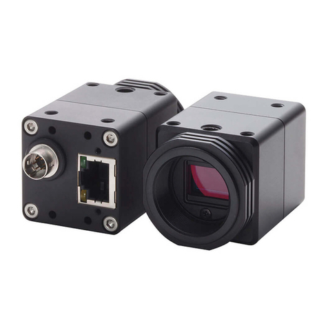
SMALL DIGITAL CAMERA FOR
MODEL FZ VISUAL INSPECTION SYSTEM
This product is not designed or rated for ensuring
safety of persons. Do not use it for such purposes.
It is likely to lose one's sight unusually.Please do not
look at the sun light directly with the lens unit.
WARNING
PRECAUTIONS ON SAFETY
PRECAUTIONS FOR SAFE USE
Be sure to respect following items for safety.
(1) Installation Site
Do not install the product in locations subjected to the following
conditions:
・Ambient temperature outside the rating
・Rapid temperature fluctuations (causing condensation)
・Relative humidity outside the range of 35 to 85%
・Presence of corrosive or flammable gases
・Presence of dust, salt, or metallic particles
・Direct vibration or shock
・Reflection of intense light (such as other laser beams or electric
arc-welding machines)
・Direct sunlight or near heaters
・Water, oil, or chemical fumes or spray
・Strong magnetic or electric field
・Near high-voltage eqipment or power eqipment
Indicates a potentially hazardous situation which, if
not avoided, may result in minor or moderate injury
or in property damage.
CAUTION
Indicates a potentially hazardous situation which, if
not avoided, will result in minor or moderate injury,
or may result in serious injury or death. Additionally
there may be significant property damage.
WARNING
The camera base attached to the bottom of the camera
amplifier can also be attached to the another side of the
camera amplifier.Remove the four screws(M2×7) from the
base and re-attach the base to the another side of the camera
amplifier.(Recommended screw tightening torque:0.32N・m)
When the plinth is attached in the top side and the side,
mount it by three mounting screws.
The camera base attached to the bottom of the camera
head can also be attached to the another side of the camera
head.Remove the four screws(M1.4×5) from the base and
re-attach the base to the another side of the camera
head.(Recommended screw tightening torque:0.15N・m)
The distance from the lens mount to plinth must note the
change from the installation of top side or the bottom
when you install it in side respect of plinth.
■Changing the base mount position of
camera amplifier(All models)
■Changing the base mount position of
camera head(FZ-SPC/SP)
■
Optical diagram
The mounting bracket of the FZ-SFC/SF attachment is fixed
by screw(M2×4 Four) that is attached to camera head in the
direction of figure below.
(Recommended screw tightening torque:0.1N・m)
Please mount it as shown in the figure below.
*
Spacer must use the length of 11mm or more to prevent
camera head from coming in contact with metallic side.
Spacer
Bottom installation
Side installation
■
Use of mounting bracket for camera head (FZ-SFC/SF)
Lens fixation ring
Lens fixation ring
Diaphragm
adjustment knob
Diaphragm adjustment knob
Diaphragm look screw
Diaphragm look screw
FZ-LES3
Focal length
Aperture F2.0
3mm
FZ-LES6
6mm
FZ-LES16
Lens: Optical glass
Outline: Aluminum alloy(CB156)
Aluminum alloy
(A5056)
FZ-LESR
F3.4
16mm
FZ-LES30
30mm
▲Performance specifications
FZ-SFC/SPC FZ-SF/SP
Item
Item
Picture element
Transmission mode
Effective pixels
Pixel size
Scanning method
Frame rate
Number of lines to be
read
Synchronization
Video output
Gain
Shutter speed
Lens mounting Special mount (M10.5 P0.5)
1/10 to 1/50000s
-6dB to + 24dB
Digital (10 bits)
Internal Sync.
12 lines to 480 lines
80fps
Non-interlace mode
7.4(µm)×7.4(µm)(Square pixel)
659(H)×494(V)
Interline reading all pixels
1/3-inch color CCD
1/3-inch monochrome CCD
Select the lens and the photograph ring referring to the table below.
Y view
Lens
WD
Photograph
ring
Camera head
(2) Loosen the lens and the photographing ring to the position
in which the focus of the image is suitable, and fix firmly
with the lens fixation ring.
(3) Rotate a knob after adjusting the brightness of the image
by the disphragm adjustment knob, detain temporarily,
and fix firmly with the fixed screw of the other side.
※Please use the draw out dimension of lens within the
above-mentioned range.The lens and the photographing
ring might come off according to the environment of use
when used by the dimension outside the range.
INSTRUCTION SHEET
Thank you for selecting OMRON product. This sheet pri-
marily describes precautions required in installing and
operating the product.
Before operating the product, read the sheet thoroughly to
acquire sufficient kno wledge of the product. For your con-
venience, keep the sheet at your disposal.
Please do not put it on the place where direct sunshine
tries the lens with the lens removed from the camera.
A fire might occur unusually.
CAUTION
Please do insert the front connector of camera amplifier
with connector of camera head, turn the ring, and fix firmly.
The model and the serial number are confirmed.
Serial number
Model
Confirm the model and serial number of the camera
amplifier and camera head is same, when connecting it.
When the camera head and the camera amplifier of a
different model and the serial number are connected, it
doesn't operate normally.
Connection of camera amplifier and camera cable
■
Connection of camera head and camera amplifier
■
Use of lens and photograph ring
(All models)
Name plate
Camera cable
FZ-VS□□
Enhancing connector
Camera cable
connector
Camera amplifier
FZ-SFC/SF/SPC/SP
(1) Using the Camera cable FZ-VS□□(sold separately),
connect the connector on the back of the camera amplifier
and the camera connector on Controller FZseries.
(1) Mount of lens as shown in the figure below, and screw in
to the inner of the camera mount. Put the photograph ring
between the camera head and the lens after referring to an
optical diagram when you want to use it in the narrowness
view and the short distance.
*The camera cable (FZ-VS,FZ-VSL,FZ-VSB) is polarized, so,
make sure that the end bearing a name plate is connected to the
Controller.
9.5
9.5±0.1
16
44
12.7
7.520
9.6
33
11.5
3000
43
16
12
9
9
M10.5
612
■Dimensions
●Camera head(FZ-SPC/SP)
●Camera amplifier(All models)
11.5
3-M2 DEPTH 3.0
3-M2 DEPTH 3.0
2-M4 DEPTH 5.5
1/4”-20UNC DEPTH 5.5
22
43.5
28
24
19±0.1 2-4.5Dia.
37 (6.5)
(6.5)
(8.8Dia.)
11.5
7.5
7.5 9.5 9.5
2.5 33.5
22
12
12
28
6.5
(8.5)
(20.7)
(Unit:mm)
FZ-LES3
Model
16.4
L
19.7
23.1
25.5
FZ-LES6
FZ-LES16
FZ-LES30
●Small lens(FZ-LES□□optional)
LDIAPHRAGM
ADJUSTMENT KNOB
DIAPHRAGM LOOK SCREW(M1.4)
12Dia. 4
(Unit:mm)
8
17
16.9
34
26
3Dia.
4-4.3Dia.
13.5
3
9.2(FROM CCD SURFACE)
3.4
12.5Dia.
2-4.3Dia.
2-M4
26±0.1
4-M4
26
17
10±0.1
M10.5
3
22
12
4.5
5.5
10
3000
43
26±0.1
●Camera head(FZ-SFC/SF)
16PIN ROUND CONNECTOR
MOUNTING SCREW HOLES1
MOUNTING SCREW HOLES2
MOUNTING SCREW HOLES
(Unit:mm)
9.2(FROM CCD SURFACE)
16PIN ROUND CONNECTOR
4-M1.7 DEPTH 1.5
8-M1.7 DEPTH 1.5
2-M3 DEPTH 4
MOUNTING SCREW HOLES
2-4.5Dia.
3Dia.
12.5Dia.
(Unit:mm)
●Photograph ring(FZ-LESR optional)
35
12Dia.
12Dia.
12Dia.
M10.5
310 3 15
M10.5
M10.5
PHOTOGRAPH RING
15mm
PHOTOGRAPH RING
10mm
PHOTOGRAPH RING
5mm
Drawing out dimension of lens
(0.7mm to 2.7mm)
Drawing out dimension of lens
(0mm to 2.0mm)
Y view(mm)
WD(mm)
1
t20
t20
t15
t25
t15
t10
t30t40t45
t50
t55
t60
t35
t5
t10
t5
t0
t0
t0
t0
10 100 1000
10
100
1000
10000
FZ-LES30
FZ-LES16
FZ-LES6
FZ-LES3
