E6F-C Incremental 60-mm-dia. Rotary Encoder 5
Operation and Installation
■Precautions
•Do not impose voltages exceeding the rated voltage on the E6F-C,
otherwise the E6F-C may be damaged.
•Be sure that the wiring of the E6F-C, including the polarity, is cor-
rect. The E6F-C may be damaged if wired incorrectly.
•Do not short the load of the E6F-C, otherwise the E6F-C may be
damaged.
•Turn OFF the E6F-C while wiring. Wiring while the power supply is
turned ON could damage the output circuit if the output cable
touches the power supply.
•Do not wire power lines or high-tension lines along with the power
supply lines of the E6F-C, otherwise the E6F-C may be damaged
or malfunction.
■Application
Mounting
Mounting Procedure
1. Insert the shaft into the Coupling.
Do not secure the Coupling and the shaft with screws at this
stage.
2. Secure the E6F-C.
Refer to the following table for the maximum insertion lengths of
the shaft into the Coupling.
3. Secure the Coupling.
4. Connect the power and I/O lines.
Turn OFF the E6F-C when connecting the lines.
5. Turn ON the E6F-C and check the output.
Mounting Information
•Be careful not to allow water, oil, or other substances to be sprayed
on the E6F-C.
•The E6F-C consists of high-precision components. Handle the
E6F-C with utmost care and do not drop it, otherwise malfunction-
ing may result.
•When the E6F-C is to be used in reversing, pay utmost attention to
the mounting direction of the E6F-C, and to the direction of incre-
ment and decrement rotation.
•To match phase Z of the E6F-C to the origin of the device to be
connected to the E6F-C, confirm the phase-Z output when con-
necting the device.
•Do not impose an excessive load on the shaft when the shaft is
connected to a gear.
•If the E6F-C is mounted with screws, the tightening torque must not
exceed 0.49 N
¼
m.
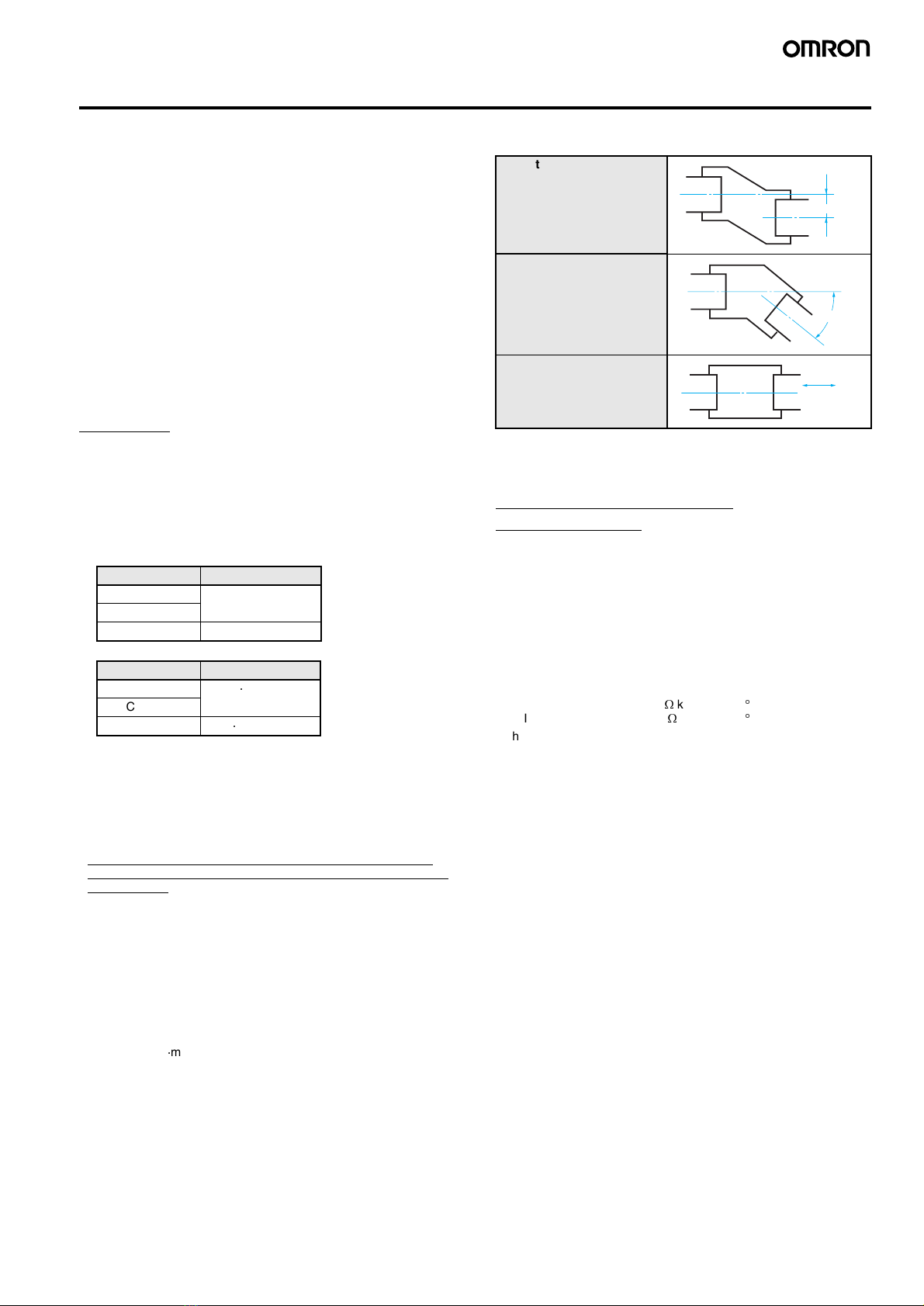
•When using a Coupling, mount within the following tolerances.
•If the eccentricity or declination value exceeds the tolerance, an
excessive load on the shaft may damage the E6F-C or shorten the
life of the E6F-C.
Wiring: Cable Extension
Characteristics
•When the cable length is extended, the output waveform startup
time is lengthened and it affects the phase difference characteris-
tics of phases A and B. Conditions will change according to fre-
quency, noise, and other factors. As a guideline, use a cable length
of 10 m or less. If extending the cable length beyond 10 m, use the
line driver output or complementary output.
(Line driver output length: 100 m max; complementary output
length: 30 m max.)
Recommended Cable:
Conductor cross-sectional area: 0.2 mm2
Spiral shield
Conductor resistance: 92
W
/km max. (20
C)
Insulation resistance: 5 M
W
/km min. (20
C)
•The output waveform startup time changes not only according to
the length of the cable, but also according to the load resistance
and the cable type.
•Extending the cable length not only changes the startup time, but
also increases the output residual voltage.
Coupling Insertion length
E69-C10B 7.1 mm
E69-C610B
E69-C10M 10.5 mm
Coupling Tightening torque
E69-C10B 0.44 N
¼
m
E69-C610B
E69-C10M 3.5 N
¼
m
Eccentricity tolerance
Declination tolerance
Displacement tolerance in
the shaft direction
0.15 mm max.
2°max.
0.05 mm max.