2E6F-A Absolute 60-mm-dia. Rotary Encoder
Specifications
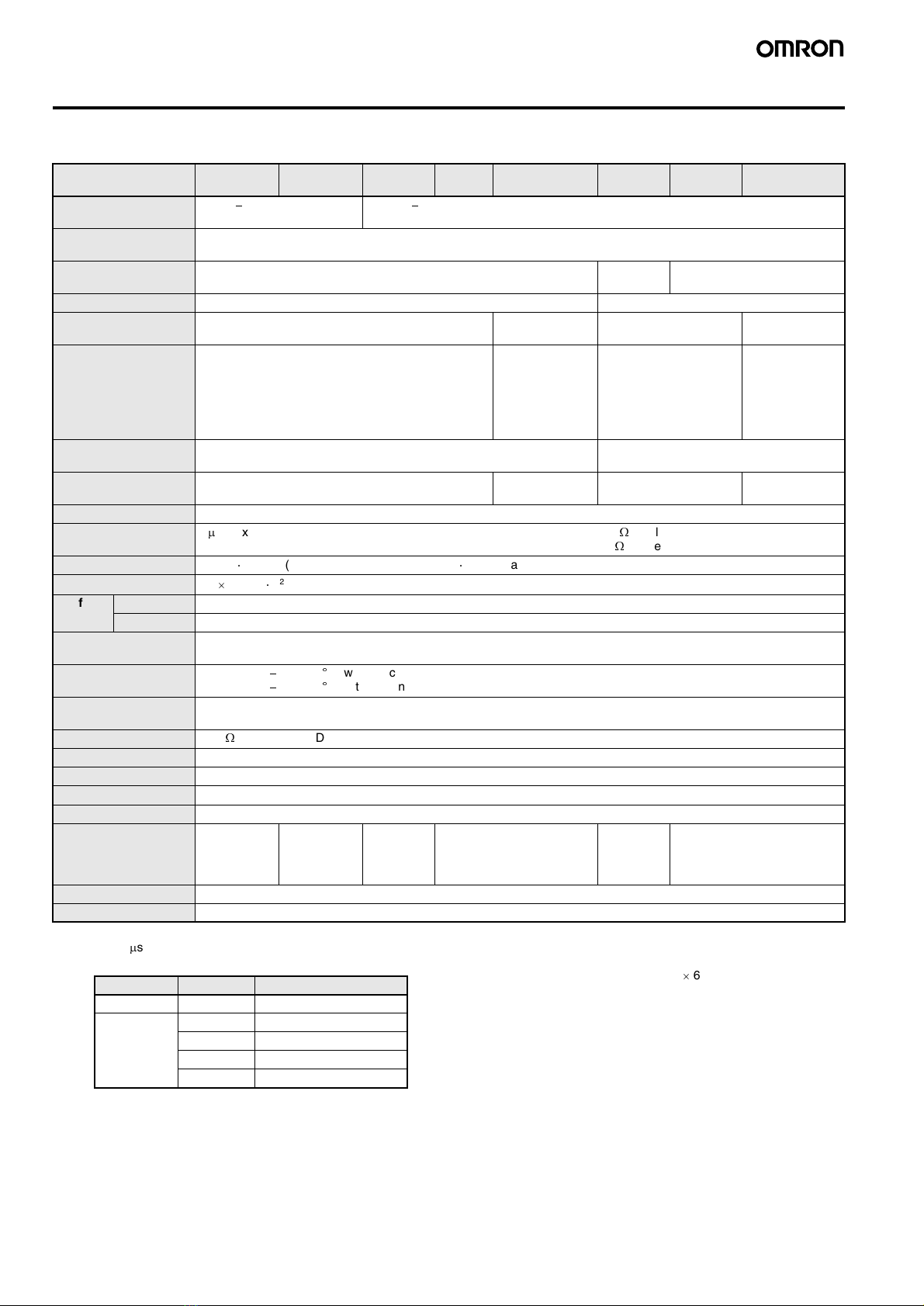
■Ratings/Characteristics
Note 1. An inrush current of approximately 9 A flows for approximate-
ly 0.5
m
s right after the E6F-A is turned ON.
2. Codes are shown in the following table.
3. The maximum electrical response revolution is determined by
the resolution and maximum response frequency as follows:
Maximum electrical response frequency (r/min) = Maximum
response frequency/resolution
60
This means that the E6F-A will not operate electrically if its
revolution exceeds the maximum electrical response revolu-
tion.
4. JEM1030: Applicable from 1991.
Item E6F-
AB3C-C
E6F-
AB3C
E6F-
AB5C-C
E6F-
AB5C
E6F-
AB5B
E6F-
AG5C-C
E6F-
AG5C
E6F-
AG5B
Power supply voltage 5 VDC
-
5% to 12 VDC +10%,
ripple (p-p): 5% max.
12 VDC
-
10% to 24 VDC +15%, ripple (p-p): 5% max.
Current consumption
(See note 1.)
60 mA max.
Resolution (P/R) (See
note 2.)
360 256 256, 360, 720, or 1,024
Output code BCD Grey binary
Output configuration NPN open collector PNP open collec-
tor
NPN open collector PNP open collec-
tor
Output capacity Applied voltage: 30 VDC max.
Sink current: 35 mA max.
Residual voltage: 0.4 V max.
(when sink current is 35 mA)
Source current:
35 mA max.
Residual voltage:
0.4 V max. (when
source current is
35 mA)
Applied voltage:
30 VDC max.
Sink current: 35 mA max.
Residual voltage: 0.4 V
max. (when sink current
is 35 mA)
Source current:
35 mA max.
Residual voltage:
0.4 V max. (when
source current is
35 mA)
Max. response fre-
quency (See note 3.)
10 kHz 20 kHz
Logic Negative logic (H = OFF; L = ON) Positive logic
(H = ON; L = OFF)
Negative logic
(H = OFF; L = ON)
Positive logic
(H = ON; L = OFF)
Rotation direction Output codes increase CW (as seen from the shaft)
Rise and fall times of
output
1
m
s max. (For E6F-AB3C and A@5C, load voltage: 5 V; load resistance: 1 k
W
; cable length: 2 m max.)
(For E6F-A@5B, power supply voltage: 12 V; load resistance: 1 k
W
; cable length: 2 m max.)
Starting torque 9.8 mN
¼
m max. (at room temperature), 14.7 mN
¼
m max. (at low temperature)
Moment of inertia 1.5
10-6 kg
¼
m2max.
Shaft
loading
Radial 120 N
Thrust 50 N
Max. permissible revo-
lution
5,000 r/min
Ambient temperature Operating:
-
10 to 70
C (with no icing)
Storage:
-
25 to 80
C (with no icing)
Ambient humidity Operating: 35% to 85% (with no condensation)
Storage: 35% to 95% (with no condensation)
Insulation resistance 10 M
W
min. (at 500 VDC) between carry parts and case
Dielectric strength 500 VAC, 50/60 Hz for 1 min between carry parts and case
Vibration resistance Destruction: 10 to 55 Hz, 1.5-mm double amplitude for 2 hrs each in X, Y, and Z directions
Shock resistance Destruction: 1,000 m/s23 times each in X, Y, and Z directions
Degree of protection IEC IP65 (JEM water-/oil-proof IP65f) (See note 4.)
Connection method Connector
(standard ca-
ble length:
2m)
Prewired
(standard ca-
ble length:
2m)
Connector
(standard
cable
length: 2 m)
Prewired (standard cable
length: 2 m)
Connector
(standard
cable
length: 2 m)
Prewired (standard cable
length: 2 m)
Weight (packed) Approx. 500 g
Accessories Servo Mounting Brackets and instruction sheet
Output code Resolution Code No.
BCD 360 0 to 359
Grey binary 256 0 to 255
360 76 to 435 (grey after 76)
720 152 to 871 (grey after 152)
1,024 0 to 1,023


