Switch Mode Power Supply S8VS 3
Specifications
■Ratings/Characteristics
Note: 1. Refer to the Engineering Data section on page 17 for details.
2. If the V.ADJ adjuster is turned, the voltage will increase by more than +15% of the voltage adjustment range. When adjusting the output voltage, confirm the actual output voltage from
the Power Supply and be sure that the load is not damaged.
3. The overvoltage protection of the S8VS-015@@ uses a zener diode clamp. If the internal feedback circuit is destroyed by any chance, the load may be destroyed by the clamped output
voltage (approx. 140% to 190% of the rated output voltage).
4. To reset the protection, turn OFF the power supply for three minutes or longer and then turn the power supply back ON.
5. The typical values indicate the values for an input condition of 230 VAC. All items are measured at a frequency of 50 Hz.
6. The inrush current circuits do not differ for voltage specifications. Therefore, the typical values are the data values for 24-V models.
7. The circuit forms are different, so the start up time is shorter only when using a 15-W power rating.
Power ratings 15 W 30 W
Type
Item
Standard Standard
Efficiency (typical) 5-V models 72% min. (76% typ.) 70% min. (76% typ.)
12-V models 74% min. (79% typ.) 76% min. (83% typ.)
24-V models 77% min. (81% typ.) 80% min. (85% typ.)
Input Voltage 100 to 240 VAC (85 to 264 VAC)
Frequency 50/60 Hz (47 to 450 Hz)
Current 100 V input 0.45 A max. 0.9 A max.
200 V input 0.25 A max. 0.6 A max.
230 V input 5 V: (0.14 A typ.), 12 V/24 V (0.19 A typ.) 5 V: (0.27 A typ.), 12 V/24 V (0.37 A typ.)
Power factor ---
Harmonic current emissions Conforms to EN61000-3-2
Leakage current 100 V input 0.5 mA max.
200 V input 1.0 mA max.
230 V input 5 V/12 V/24 V: (0.30 mA typ.) 5 V/12 V/24 V:(0.32 mA typ.)
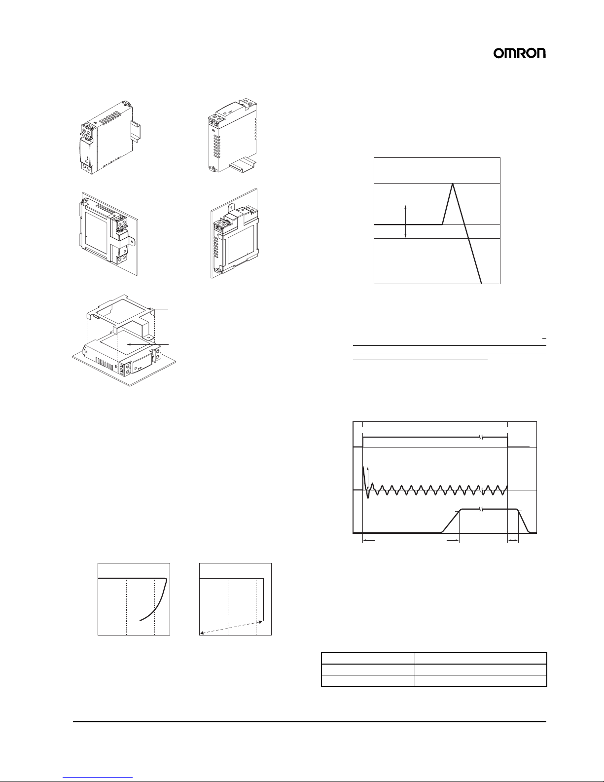
Inrush current
(See note 1.)
100 V input 25 A max. (20 A typ.) (for a cold start at 25°C)
200 V input 50 A max. (40 A typ.) (for a cold start at 25°C)
230 V input 5 V/12 V/24 V: (29 A typ.) (See note 6.) 5 V/12 V/24 V: (40 A typ.) (See note 6.)
Output Voltage adjustment range
(See note 2.)
−10% to 15% (with V.ADJ) (guaranteed)
Ripple 2.0% (p-p) max. (at rated input/output voltage)
f=20MHz measuring 5 V: (0.70%(p-p) typ.), 12 V:(0.48%(p-p) typ.), 24 V:(0.25%(p-p)
typ.)
5 V: (0.70%(p-p) typ.), 12 V:(0.52%(p-p) typ.), 24 V:(0.19%(p-p)
typ.)
f=100MHz measuring 5 V: (0.86%(p-p) typ.), 12 V:(0.56%(p-p) typ.), 24 V:(0.32%(p-p)
typ.)
5 V: (0.80%(p-p) typ.), 12 V:(0.58%(p-p) typ.), 24 V:(0.21%(p-p)
typ.)
Input variation influence 0.5% max. (at 85 to 264 VAC input, 100% load)
Load variation influence (rated input voltage) 2.0% max. (5 V), 1.5% max. (12 V, 24 V), (with rated input, 0 to 100% load)
Temperature variation influence 0.05%/°C max.
Start up time (See note 1 and 7.) 100 ms max. (at rated input/output voltage) 1,000 ms max. (at rated input/output voltage)
5 V: (6 ms typ.), 12 V: (12 ms typ.), 24 V: (18 ms typ.) 5 V/12 V/24 V: (240 ms typ.)
Hold time (See note 1.) 20 ms min. (at rated input/output voltage)
at 100% load 5 V: (328 ms typ.), 12V: (251 ms typ.), 24 V: (243 ms typ.) 5 V: (299 ms typ.), 12 V: (217 ms typ.), 24 V: (210 ms typ.)
Additional
functions
Overload protection (See note 1.) 105% to 160% of rated load current, voltage drop, automatic re-
set
105% to 160% of rated load current, voltage drop, intermittent
operation, automatic reset
Overvoltage protection (See note 1.) Yes (a zener diode clamp) (See note 3.) Yes (See note 4.)
Output voltage indication No
Output current indication No
Peak-hold current indication No
Maintenance forecast monitor indication No
Maintenance forecast monitor output No
Total run time monitor indication No
Total run time monitor output No
Undervoltage alarm indication Yes (color: red)
Undervoltage alarm output No
Parallel operation No
Series operation Models with 24-V output: Possible for up to 2 Power Supplies (with external diode)
Models with 5- or 12-V output: Not possible
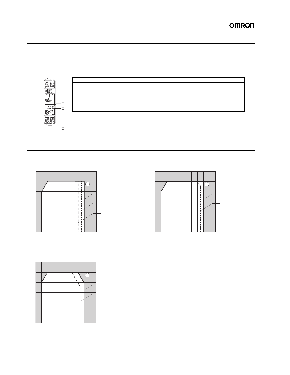
Other Operating ambient temperature Refer to the derating curve in Engineering Data. (with no icing or condensation)
Storage temperature −25 to 65°C
Operating ambient humidity 25% to 85% (Storage humidity: 25% to 90%)
Dielectric strength 3.0 kVAC for 1 min. (between all inputs and outputs; detection current: 20 mA)
2.0 kVAC for 1 min. (between all inputs and PE terminals; detection current: 20 mA)
1.0 kVAC for 1 min. (between all outputs and PE terminals; detection current: 20 mA)
Insulation resistance 100 MΩmin. (between all outputs and all inputs/ PE terminals) at 500 VDC
Vibration resistance 10 to 55 Hz, 0.375-mm single amplitude for 2 h each in X, Y, and Z directions
10 to 150 Hz, 0.35-mm single amplitude (5 G max.) for 80 min. each in X, Y, and Z directions
Shock resistance 150 m/s2, 3 times each in ±X, ±Y, and ±Z directions
Output indicator Yes (color: green)
EMI Conducted
Emissions
Conforms to EN61204-3 EN55011 Class B and based on FCC Class A
Radiated
Emissions
Conforms to EN61204-3 EN55011 Class B
EMS Conforms to EN61204-3 high severity levels
Approved standards UL: UL508 (Listing, Class 2: Per UL1310), UL60950-1, UL1604 (Class I/Division2)
cUL: CSA C22.2 No.14 (Class 2), No.60950-1, No.213 (Class I/Division2)
EN/VDE: EN50178 (=VDE0160), EN60950-1 (=VDE0805)
SELV (EN60950/EN50178/UL60950-1)
According to VDE0106/P100, IP20
Weight 160 g max. 180 g max.