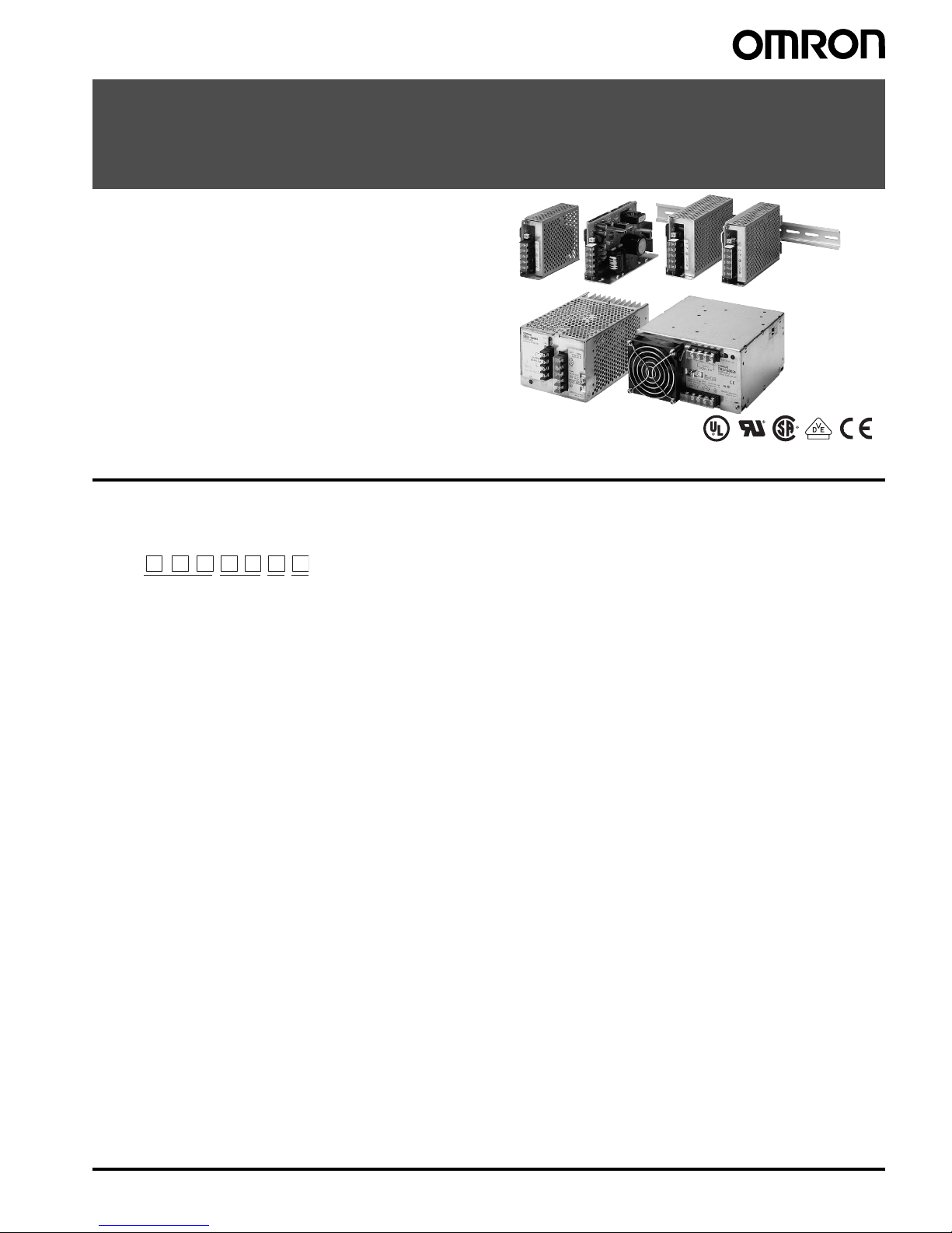
4Switch Mode Power Supply S82J
Specifications
■Ratings/Characteristics
Power ratings
(See note 1.)
100 to 240 V (Free) 100/200 (Selected
automatically)
100/200 (Selected)
10 W 25 W 50 W 100 W
(24 V)
100 W (5 V,
12 V, 15 V)
150 W 300 W 600 W
Efficiency (typical) 67% min. (Varies depending on
specifications)
83% min. 75% min. 82% min.
Input Voltage (See note 2.) 100 to 240 VAC (85 to 264 VAC) 100 VAC (85 to 132 VAC)
200 VAC (170 to 264 VAC)
(selected automatically)
100 VAC (85 to 132 VAC)
200 VAC (170 to 253 VAC)
(selectable)
110 to 170 VDC (10-W and 25-W models only) (See
note 11.)
Frequency (See note 2.) 50/60 Hz (47 to 450 Hz)
Current
(See note 3.)
100-V input 0.35 A max. 0.8 max. 1.4 A max. 2.5 A max. 2.5 A max. 3.5 A max. 8 A max. 14 A max.
200-V input 0.3 A max. 0.6 A max. 0.8 A max. 1.5 A max. 1.4 A max. 2.1 A max. 4 A max. 7 A max.
Leakage current
(See note 3.)
100-V input 0.5 mA max.
200-V input 1 mA max.
Inrush current
(See note 3.)
100-V input 25 A max. (for cold start at 25°)30 A max. (for cold
start at 25°)
200-V input 50 A max. (for cold start at 25°)60 A max. (for cold
start at 25°)
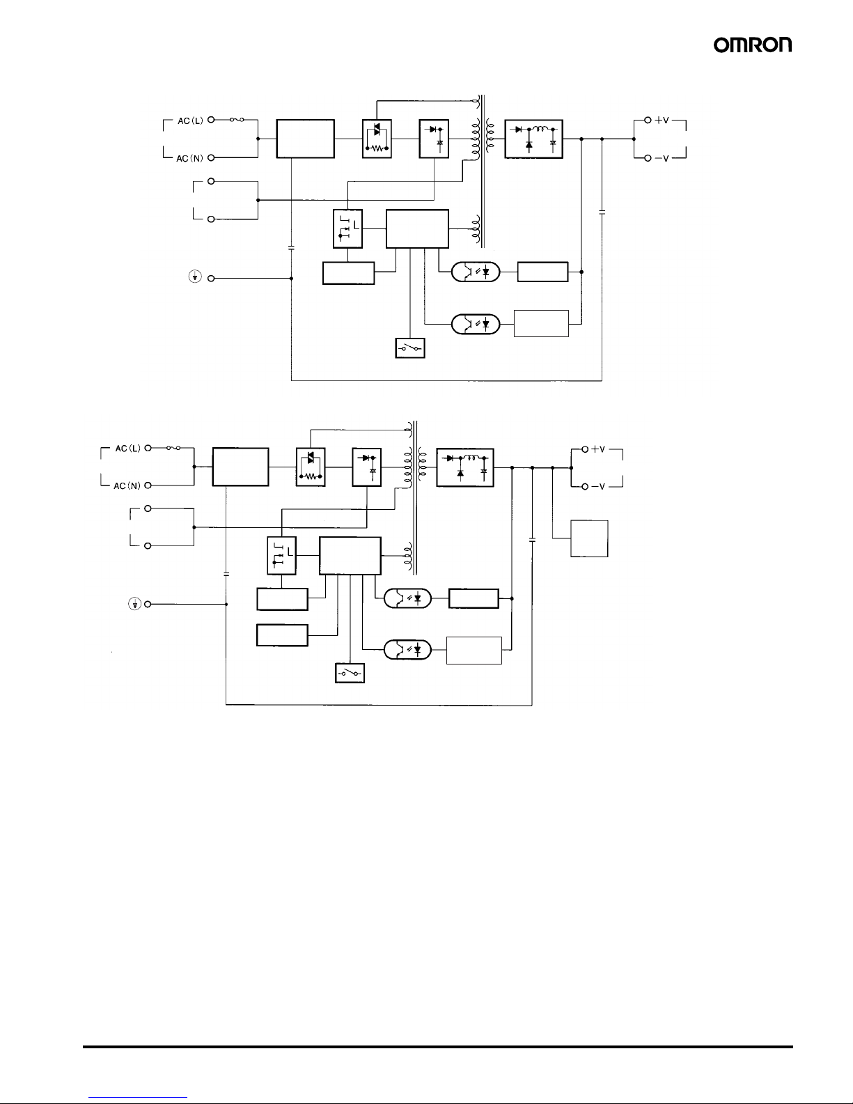
Noise filter Yes
Output
(See
note 4.)
Voltage Adjustment Range
(See note 5.)
±10% (with V. ADJ)
Ripple (See note 3.) 2% (p-p) max.
Input variation influence 0.4% max.
Load variation influence 0.8% max. (10% to 100% load, rated input voltage)
Temperature variation
influence
0.05%/°max. (at rated input and output)
Start up time 500 ms max. (up to 90% of output voltage at rated input and output) 300 ms max. (up to 90% of output
voltage at rated input and output)
Hold time (See note 3.) 20 ms min.
Addi-
tional
func-
tions
Overload protection (See note
6.)
105% to 160% of rated load current, voltage/current drop, intermittent operation (10-W
and 25-W models) gradual current increase/ voltage drop, intermittent operation (50-
W, 100-W (24 V) models), automatic reset
105% of rated load current, Inverted
L voltage drop, automatic reset (For
the 600-W model, the circuit will be
shut OFF when the overload
exceeds 5 s.)
Overvoltage protection No Yes (See
note 7.)
Yes (5-V output
only) (See note
7.)
No Yes (See note 8.)
Overheat protection No Yes (See note 8.)
Parallel operation No Yes (up to 5 units)
Protection-ON alarm indicator No Yes (color: red)
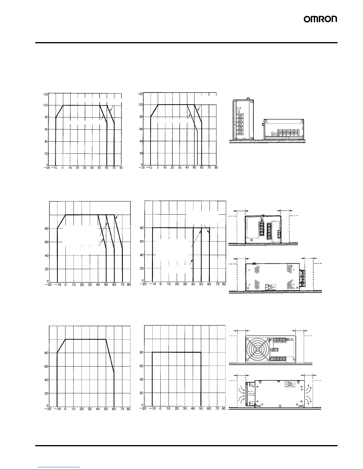
Other Operating ambient
temperature
Refer to the derating curve in Engineering Data. (with no icing or condensation)
Storage temperature −25 to 65°C (with no icing or condensation)
Operating ambient humidity 25% to 85% (Storage humidity: 25% to 90%)
Dielectric strength 3.0 k VAC for 1 min. (between all inputs and all outputs)
2.2 k VAC for 1 min. (between all inputs and all outputs/PE terminals)
1.0 k VAC for 1 min. (between all outputs and all PE terminals)
Insulation resistance 100 MΩmin. (between all outputs and all inputs/ PE terminals) at 500 VDC
Vibration resistance 10 to 55 Hz, 0.375-mm single amplitude for 2h each in X, Y, and Z directions
Shock resistance 300m/s2, 3 times each in ±X, ±Y, ±Z directions
Output indicator Yes (color: green)
EMI Conducted
Emissions
(See note 3.)
Conforms to EN61204-3 EN55011 Class A and based on FCC Class A
Radiated
Emissions
Conforms to EN61204-3 EN55011 Class A (See note. 9)
EMS Conforms to EN61204-3 Low severity levels
Approved standards UL: UL508 (Listing, Class 2), No. 60950-1
(Class 2 approved for 10-W, 25-W (except for
5-V output), and 50-W (only for 24-V output)
models.)
CSA: cUL: C22.2 No.14 (Class 2), cUR: No.
60950-1 (Class 2 approved for 10-W, 25-W
(except for 5-V output), and 50-W (only for 24-
V output) models.)
EN/VDE: EN50178 (VDE0160), EN60950-1
(VDE0805 Teil 1)
Terminal types (only terminal part):
VDE0106/P100
Based on VE0106/P100
UL: UL 508 (Listing), 1012, 60950-1
CSA: cUL: C22.2 No. 14, cUR: No. 60950-1
EN/VDE: EN50178 (VDE0160), EN60950-1
(VDE0805 Teil 1)
Terminal types (only terminal part):
VDE0106/P100
Based on VE0106/P100
UL: UL 508 (Listing), 1012, 60950-1
CSA: cUL: C22.2 No. 14, cUR: No. 60950-
1
EN/VDE: EN50178 (VDE0160),
EN60950-1 (VDE0805 Teil 1)
Ter min al types (only terminal par t):
VDE0106/P100
Based on VE0106/P100
Weight 250 g max. 350 g max. 400 g max. 500 g max. 1,000 g max. 2,000 g max. 2,500 g max.