Omron ZFV-SR10 User manual

Smart Sensors (with Ultra-High-Speed CCD Camera) ZFV Series 1
Smart Sensors (with Ultra-High-Speed CCD Camera)
ZFV Series
Ordering Information
Sets of Sensor Head and Amplifier Unit
Sensor Heads
Amplifier Units
Type NPN PNP
Narrow View/Single Function ZFV-R1010 ZFV-R1015
Narrow View/Standard ZFV-R1020 ZFV-R1025
Wide View/Single Function ZFV-R5010 ZFV-R5015
Wide View/Standard ZFV-R5020 ZFV-R5025
Appearance Type Working length Sensing area Model
Narrow View 34 to 49 mm (variable) 5 ×4.6 mm (H ×V) to
9 ×8.3 mm (H ×V) ZFV-SR10
Wide View 38 to 194 mm (variable) 10 ×9.2 mm (H ×V) to
50 ×46 mm (H ×V) ZFV-SR50
Appearance Type Power supply Output type Model
Single Function 24 VDC ±10% NPN ZFV-A10
PNP ZFV-A15
Standard NPN ZFV-A20
PNP ZFV-A25

2 Smart Sensors (with Ultra-High-Speed CCD Camera) ZFV Series
Accessories (Order Separately)
Data Storage Units
Controller Link Unit Panel-mounting Adapter
Sensor Head Extension Cable
Note:ZFV-XC3BR Robot Cable is also available.
Specifications
Sensor Heads
Appearance Power supply Output type Model
24 VDC NPN ZS-DSU11
PNP ZS-DSU41
Appearance Model
ZS-XCN
Appearance Model
ZS-XPM1 First Unit
ZS-XPM2 Additional Units
(for expansion)
Cable length Model Quantity
3 m ZFV-XC3B (See note.) 1
8 m ZFV-XC8B 1
Item ZFV-SR10 (Narrow View) ZFV-SR50 (Wide View)
Setting distance (L) 34 to 49 mm 38 to 194 mm
Detection range (H ×V) 5 ×4.6 mm to 9 ×8.3 mm 10 ×9.2 mm to 50 ×46 mm
Relation between setting
distance and detection range
Guide light Provided (center, sensing area)
Built-in lens Focus: f15.65 Focus: f13.47
Object lighting method Pulse lighting
Object light source Eight red LEDs
Sensing element 1/3-inch CCD, partial scan
Shutter Electronic shutter, shutter time: 1/1,000 to 1/4,000
Power supply voltage 15 VDC (Supplied from Amplifier Unit.)
Current consumption Approx. 200 mA
Dielectric strength 1,000 VAC, 50/60 Hz for 1 min
Vibration resistance
(destruction) 10 to 150 Hz, 0.35-mm single amplitude, 10 times each in X, Y, and Z directions for 8 min
Shock resistance (destruction) 150 m/s2, three times each in six directions (up/down, left/right, forward/backward)
Ambient temperature Operating: 0 to 40°C, Storage: −25 to 65°C (with no icing or condensation)
Ambient humidity Operating and storage: 35% to 85% (with no condensation)
Ambient atmosphere Must be free of corrosive gas.
Connection method Prewired, Standard cable length: 2 m
Degree of protection IEC60529, IP65
Materials Case: ABS, Mounting bracket: PBT
Weight Approx. 200 g (including mounting bracket and cord)
Accessories Mounting bracket (1), Ferrite core (1), Instruction sheet
49 mm
Setting distance
(L)
34 mm
5 mm 9 mm Detection range
(H) 10 mm
194 mm
38 mm
50 mm
Setting distance
(L)
Detection range
(H)

Smart Sensors (with Ultra-High-Speed CCD Camera) ZFV Series 3
Amplifier Units
Note 1. This is the sampling rate when logging images. To log measurement data only, use the ZS-DSU settings.
2. Image logging is not possible when the ZS-MDC is connected.
Item Single-function models Standard models
ZFV-A10 ZFV-A15 ZFV-A20 ZFV-A25
Output method NPN PNP NPN PNP
Inspection items Pattern (PTRN), Brightness (BRGT) Patterns (PTRN), Brightness (BRGT), Area (AREA), Width
(WID), Position (POSI), Count (CNT), Characters (CHAR)
Teaching area Rectangular, one area
Teaching area size •Pattern (PTRN), Brightness (BRGT): Any rectangular area (256 ×256 max.)
•Area (AREA), Width (WID), Position (POSI), Count (CNT), Characters (CHAR): Any rectangular area (full screen max.)
Sensing area Full screen
Resolution 468 ×432 (H ×V) max.
Bank selection Supported for 8 banks.
Response time Pattern (PTRN), Brightness (BRGT): High-speed: 4 ms, Standard: 8 ms, High-precision: 12 ms
Area (AREA), Width (WID), Position (POSI), Count (CNT), Characters (CHAR): 128 ×128: 15 ms max.
Other functions Control output switching: ON for OK or ON for NG
ON delay/OFF delay, One-shot output, “ECO” mode
Output signals (1) Control output (OUTPUT), (2) Enable output (ENABLE), (3) Error output (ERROR)
Input signals (1) Simultaneous measurement input (TRIG) or Continuous measurement input (TRIG), Switched by using menu.
(2) Bank selection inputs (BANK1 to BANK3)
(3) Workpiece still teaching (TEACH) or Workpiece moving teaching (TEACH), Switched by using menu.
Con-
necting
to ZS-
DSU
Image
logging
trigger
Stores NG images or all images.
Sampling
rate ZFV measurement cycle (See note 1.)
Number of
logged
image
Logs up to 128 images in series
Number of
connected 15 max. (ZFV: 5 Units max., ZS-LDC: 9 Units max., ZS-MDC (See note 2.): 1 Unit max.)
External
bank
function
Amplifier Unit setting data can be saved to the memory card as bank data. Reading bank data enables bank switching.
Sensor Head
interface Digital interface
Image display Compact TFT 1.8-inch LCD (Display dots: 557 ×234)
Indicators •Judgement result indicator (OUTPUT) •Inspection mode indicator (RUN)
Operation interface •Cursor keys (up, down, left, right) •Setting key (SET) •Escape key (ESC)
•Operating mode switching (slide switch) •Menu switching (slide switch)
•Teaching/Display switching key (TEACH/VIEW)
Power supply voltage 20.4 to 26.4 VDC (including ripple)
Current consumption 600 mA max. (with Sensor Head connected)
Dielectric strength 1,000 VAC, 50/60 Hz for 1 min between leads and Amplifier Unit case
Noise immunity 1 kV, Pulse rise: 5 ns, Pulse width: 50 ns, Burst duration: 15 ms, Cycle: 300 ms
Vibration resistance Destruction: 10 to 150 Hz, 0.1-mm single amplitude, 10 times each in X, Y, and Z directions for 8 min
Shock resistance Destruction: 150 m/s2, three times each in six directions (up/down, left/right, forward/backward)
Ambient temperature Operating: 0 to 50°C
Storage: −25 to 65°C (with no icing or condensation)
Ambient humidity Operating and storage: 35% to 85%
Ambient atmosphere Must be free of corrosive gas.
Degree of protection IEC60529, IP20
Materials Polycarbonate
Weight Approx. 300 g (including cord)
Accessories Ferrite core (1), Instruction sheet
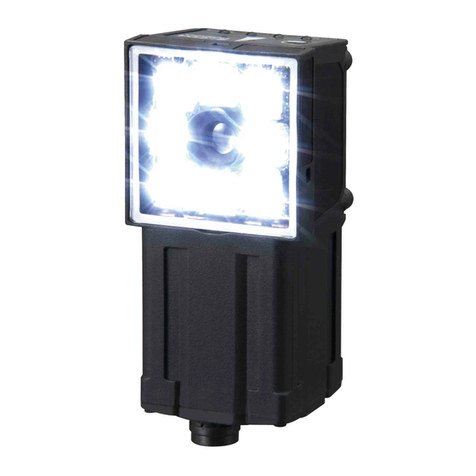
4 Smart Sensors (with Ultra-High-Speed CCD Camera) ZFV Series
Dimensions
Note:All units are in millimeters unless otherwise indicated.
Amplifier Units
33.6 3
0
(6.36)
30 (6.36)
4
20
32
4.5
R2
R2
4.5 67.9
17.9 5.6
32
12.8
dia.
4.5
R6.5
4.5
20±0.1
Two, M4
Two, M4
Depth: 6
34
17.9
Mounting Bracket can be attached to any side.
23.3
R2
R2
Mounting Hole Dimensions
Heat-resistive vinyl-insulated cable
5.8 dia, standard length: 2 m
8.5
30.1
33
1/4-20UNC
Depth: 6
Sensor Heads
ZFV-SR@
52.5
90 90
3.9
4.6
60 23.4
23.2
14.8
4.2
18
Heat-resistive vinyl-insulated cabl
e
5.2 dia., standard length: 2 m
11.7 dia.
ZFV-A@

Smart Sensors (with Ultra-High-Speed CCD Camera) ZFV Series 5
About the I/O cable
The following shows the leads that comprise the I/O cable.
1. Power supply
This connects the power supply.
Supply power from a DC power supply unit that
has a countermeasure (safety ultra-low voltage
circuit) built-in for preventing high voltages from
occurring.
Wire the power supply separately from other
devices. Wiring them together or placing them in
the same duct may cause induction, resulting in
malfunction or damage.
2. GND
3. OUTPUT (control output)
This outputs judgment results.
This lead is interlocked with OUTPUT LED.
4. ENABLE (enable output)
5. ERROR (error output)
This turns ON when an error is generated.
6. TEACH (teaching input)
There are two teaching modes, workpiece stop teaching and
workpiece move teaching. These teaching modes can be
selected in the menu.
7. TRIG (measurement trigger input)
There are two measurement modes, synchronous measure-
ment and continuous measurement. Which mode of measure-
ment is to be performed in is selected in the menu.
8. BANK1 (bank switching input 1)
9. BANK2 (bank switching input 2)
10. BANK3 (bank switching input 3)
(1) Power supply
(3) OUTPUT*
(4) ENABLE
(5) ERROR
(6) TEACH*
(7) TRIG*
(8) BANK1*
(9) BANK2*
(10) BANK3*
(2) GND
Brown
Blue
Black
Orange
Light blue
Yellow
Pink
Gray
Green
Red
* : Enabled only in the RUN mode
Purple
White Unused
Unused

6 Smart Sensors (with Ultra-High-Speed CCD Camera) ZFV Series
I/O Circuit Diagrams
NPN output type (ZFV-A10/A20)
PNP output type (ZFV-A15/A25)
Brown
Blue
Black
Orange
Light blue
Load
Load
Load
Power supply (24VDC)
24VDC
Yellow
Pink
Gray
Green
Red
OUTPUT
ENABLE
ERROR
GND(0V)
TEACH
TRIG
BANK1
BANK2
BANK3
Internal circuits
Brown
Blue
Black
Orange
Light blue
Load
Power supply (24VDC)
OUTPUT
ENABLE
ERROR
GND(0V)
24VDC
Yellow
Pink
Gray
Green
TEACH
TRIG
BANK1
BANK2
Red BANK3
Load
Load
Internal circuits

Smart Sensors (with Ultra-High-Speed CCD Camera) ZFV Series 7
Timing charts
The following shows the timing charts when communication is performed with external devices.
Measurement
Continuous measurement
Measurement is performed continuously for the duration that the TRIG signal is ON.
The measurement result is updated, and output to external devices at each measurement cycle.
Synchronous measurement
Measurement is performed only once in synchronous with the change
in TRIG signal state from OFF to ON, and the result is output.
• The minimum ON width of the TRIG signal is 1 ms.
• The OUTPUT signal is held until the next measurement result is updated.
Note, however, that when one-shot output is currently set, the OUTPUT signal is held for the preset time.
Teaching
Workpiece stop teaching
Teaching processing is performed according to TRIG signal input after the TEACH signal is input from the outside.
Measurement is not performed while teaching is being performed. Do not move the workpiece until teaching is completed.
1. Turn the TEACH signal ON.
2. Confirm that the ENABLE signal has turned OFF.
3. Make sure that the workpiece to be taught is in the teaching area.
4. Input the TRIG signal from the outside.
5. The ENABLE signal turns ON after teaching is completed. At this timing, check the state of the ERROR signal.
6. When teaching has been completed successfully, the ERROR signal stays OFF.
7. When teaching fails, the ERROR signal turns ON.
8. Turn the TEACH signal OFF, and end teaching processing.
When teaching fails, the state before teaching was initiated is returned to. Perform teaching again.
If the TEACH signal is turned OFF midway, teaching is disabled.
Tou t
TRIG
OUTPUT
ENABLE
OFF
ON
OFF
ON
OFF
ON
Tout: Measurement cycle
The measurement cycle changes
depending on the setting.
Tou t
TRIG
OUTPUT
ENABLE
OFF
ON
OFF
ON
OFF
ON
Tout: Measurement time.
The measurement time changes
depending on the setting.
During teaching processing
TRIG OFF
ON
TEACH OFF
ON
ENABLE OFF
ON
ERROR OFF
ON
(1)
(2)
(4)
(5)
(7)
(6)
(8)

8 Smart Sensors (with Ultra-High-Speed CCD Camera) ZFV Series
Workpiece move teaching
Use this teaching mode when the object cannot be stopped.
Teaching processing is divided up and performed in synchronous with the TRIG signal input after the TEACH signal is input from the outside.
Teaching must be processed six times.
Measurement is not performed while teaching is being performed.
1. Turn the TEACH signal ON from the outside.
2. Confirm that the ENABLE signal has turned OFF.
3. Input the TRIG signal at the timing for measuring the workpiece to be taught.
4. Repeat the input in step (3) six times. (Trigger inputs from the seventh time onwards are ignored.)
5. The ENABLE signal turns ON after teaching is completed. Check the state of the ERROR signal at this timing.
6. When teaching has been completed successfully, the ERROR signal stays OFF.
7. When teaching fails, the ERROR signal turns ON.
8. Turn the TEACH signal OFF, and end teaching processing.
When teaching fails, the state before teaching was initiated is returned to. Perform teaching again.
If the TEACH signal is turned OFF midway, teaching is disabled.
Bank switching
The bank No. can be switched when BANK1o BANK3 are connected as follows.
Bank No. BANK1 BANK2 BANK3
BANK1 OFF OFF OFF
BANK2 ON OFF OFF
BANK3 OFF ON OFF
BANK4 ON ON OFF
BANK5 OFF OFF ON
BANK6 ON OFF ON
BANK7 OFF ON ON
BANK8 ON ON ON
During teaching processing
Min.150ms
TEACH OFF
ON (1) (8)
ERROR OFF
ON (6)
(7)
ENABLE OFF
ON (2) (5)
TRIG OFF
ON (3) (4)
In the interest of product improvement, specifications are subject to change without notice.Cat. No. Z205-E2-02A-X
OMRON EUROPE B.V.
Wegalaan 67-69,
NL-2132 JD, Hoofddorp,
The Netherlands
Phone: +31 23 568 13 00
Fax: +31 23 568 13 88
www.eu.omron.com
This manual suits for next models
7
Table of contents
Other Omron Security Camera manuals

Omron
Omron FQ2 Series User manual

Omron
Omron STC-S133MIP Series Installation instructions

Omron
Omron FQ2-S/CH Series User manual

Omron
Omron FQ2-S Series User manual

Omron
Omron Sentech STC-CMC120APCL Series Installation instructions

Omron
Omron Sentech STC-CMB200PCL Installation instructions

Omron
Omron STC-MBS891U3V Installation instructions

Omron
Omron ZFV-C User manual