One Stop Gardens 47712 Assembly instructions

Visit our website at: http://www.harborfreight.com
47712
Greenhouse
8’5" L x6’3" W x6’5" H
Owner’s Manual & Safety Instructions
Save This Manual Keep this manual for the safety warnings and precautions, assembly,
operating, inspection, maintenance and cleaning procedures. Write the product’s serial number in the
back of the manual near the assembly diagram (or month and year of purchase if product has no number).
Keep this manual and the receipt in a safe and dry place for future reference. 23i
When unpacking, make sure that the product is intact
and undamaged. If any parts are missing or broken,
please call 1-888-866-5797 as soon as possible.
Copyright©2023 by Harbor Freight Tools®. All rights reserved.
No portion of this manual or any artwork contained herein may be reproduced in
any shape or form without the express written consent of Harbor Freight Tools.
Diagrams within this manual may not be drawn proportionally. Due to continuing
improvements, actual product may differ slightly from the product described herein.
Tools required for assembly and service may not be included.
Read this material before using this product.
Failure to do so can result in serious injury.
SAVE THIS MANUAL.

Page 2 For technical questions, please call 1-888-866-5797. Item 47712
Table of Contents
Safety ......................................................... 3
Specifications ............................................. 4
Foundation.................................................. 4
Frame ......................................................... 8
Panels........................................................ 16
Maintenance.............................................. 17
Parts Lists.................................................. 18
Warranty .................................................... 20
WARNING SYMBOLS AND DEFINITIONS
This is the safety alert symbol. It is used to alert you to potential
personal injury hazards. Obey all safety messages that
follow this symbol to avoid possible injury or death.
Indicates a hazardous situation which, if not avoided,
will result in death or serious injury.
Indicates a hazardous situation which, if not avoided,
could result in death or serious injury.
Indicates a hazardous situation which, if not avoided,
could result in minor or moderate injury.
Addresses practices not related to personal injury.
SAFETY ASSEMBLY MAINTENANCEFOUNDATION

Page 3For technical questions, please call 1-888-866-5797.Item 47712
IMPORTANT SAFETY INFORMATION
The warnings, precautions, and instructions discussed in this manual cannot cover all possible conditions
and situations that may occur. The operator must understand that common sense and caution are factors,
which cannot be built into this product, but must be supplied by the operator.
Assembly / Installation Precautions
1. Assemble only according to these instructions.
Improper assembly can create hazards.
2. Wear ANSI-approved safety goggles and
heavy-duty work gloves during assembly.
3. This unit contains pieces with sharp edges.
The machined edges of the aluminum parts
and the ends of the panel clips may be sharp.
Handle all parts carefully.
4. Keep assembly area clean and well lit.
5. Keep bystanders out of the area during assembly.
6. Do not assemble when tired or when under the
influence of alcohol, drugs or medication.
7. Product capabilities apply to properly and
completely assembled product only.
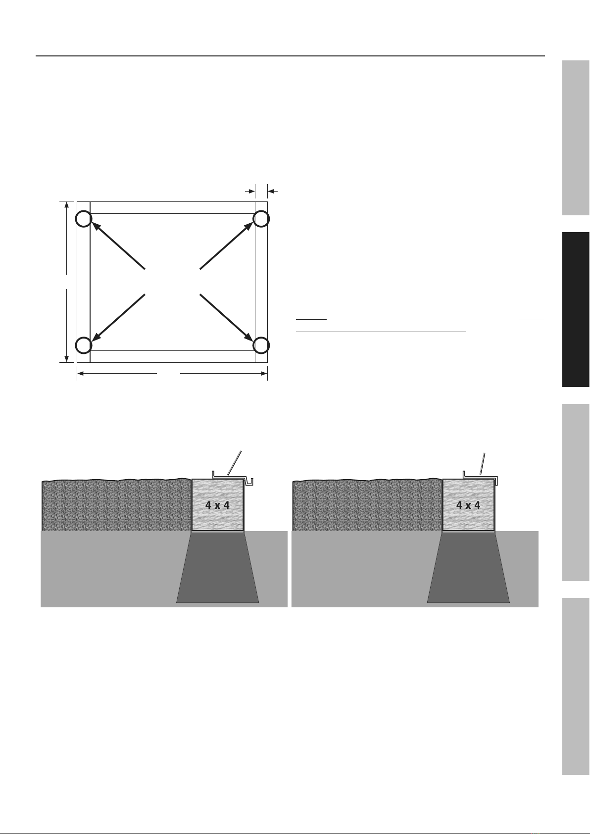
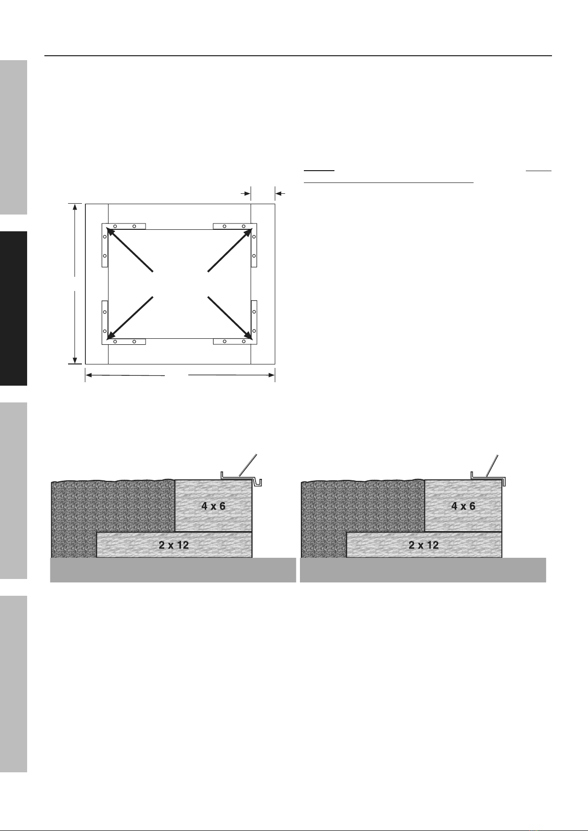
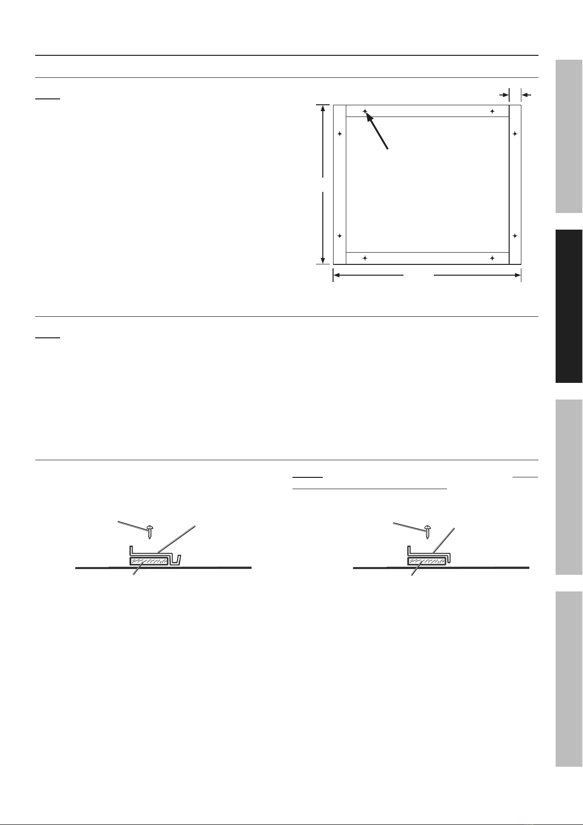
8. Locate the Greenhouse on a flat, level,
surface. A concrete foundation is
recommended for a high-quality installation.
Use / Service Precautions
1. This product is not a toy. Do not allow
children to play in or climb on this product.
Although this greenhouse does include some caps,
there are still some exposed sharp edges.
In addition, protective covers may fall off in time.
Children must be supervised if
allowed near the greenhouse.
2. SNOW/DEBRIS ACCUMULATION HAZARD.
The heavy weight of accumulated snow or other
debris can cause parts of this greenhouse to buckle
suddenly. Do not allow debris to accumulate on top
of the greenhouse. If snowfall is expected, place
additional supports (sold separately) underneath
the Crown (35). NEVER enter a greenhouse
with accumulated debris on top.
3. Use as intended only.
4. Inspect periodically; replace damaged parts
immediately and do not enter greenhouse
if parts are loose or damaged.
5. For your safety, service and maintenance should
be performed regularly by a qualified technician.
SAVE THESE INSTRUCTIONS.
SAFETYASSEMBLYMAINTENANCE FOUNDATION

Page 4 For technical questions, please call 1-888-866-5797. Item 47712
Specifications
Overall Dimensions 8' 5" L x 6' 3" W x 6' 5" H
Window Dimensions 23" L x 20" W
Door Dimensions 64" H x 24" W x 1-1/4" Thick
Materials Aluminum Frame
Transparent Polycarbonate Sheets
Aluminum Thickness 0.038"
Polycarbonate Sheet Thickness 0.165"
Foundation Installation
Read the ENTIRE IMPORTANT SAFETY INFORMATION section at the beginning of this document
including all text under subheadings therein before set up or use of this product.
IMPORTANT–READ THE FOLLOWING CAREFULLY BEFORE PROCEEDING
•• Prior to assembly, a proper foundation must be laid. The greenhouse must be properly
supported to help prevent property damage and injury in the event of strong winds or
inclement weather. Wind and ground conditions may vary from site to site, and may affect
the practicality and effectiveness of anchoring methods substantially. If you have any
doubt regarding the stability of the foundation you are to use, consult a professional.
• It is always your responsibility to ensure that the greenhouse is properly anchored.
Harbor Freight Tools cannot be held responsible for personal injury, damage to the greenhouse,
or other property damage that occurs as a result of improperly anchoring the greenhouse.
• Be certain to check with local authorities to obtain all required building permits
and to familiarize yourself with any building codes that may apply.
• Decide on a location for the greenhouse. The location should optimally be a
level, well-lit area that is sheltered from the wind. The door of the greenhouse
should not open towards the prevailing wind, if possible.
SAFETY ASSEMBLY MAINTENANCEFOUNDATION

Page 5For technical questions, please call 1-888-866-5797.Item 47712
Concrete Anchor Foundation
1. Frame is assembled out of 4 x 4 treated lumber,
appropriate hardware, and prefabricated
concrete anchors (sold separately).
2. Assemble 4 x 4 pieces to dimensions shown
(See Figure A.) Trim wood to fit. Confirm assembly
is square and level. Diagonal dimensions,
from outside corners should be 122-1/8".
3. Assemble frame together using hardware.
Concrete Anchor
Locations
75-1/4"
4"
97"
Figure A: Wood Frame Dimensions
4. Dig a hole for each concrete anchor in
locations shown (See Figure A.) Holes should
be slightly oversized and deep enough so
installed frame almost rests on the ground.
5. Place an anchor in each hole, and the frame
on the anchors. Use a level on the frame to
confirm anchors are sunk to proper depth.
If an anchor needs to be raised, partially fill
hole under anchor with sand or gravel.
6. With frame level, secure it to the anchors.
Fill holes fully with earth removed previously.
7. Optional: For convenience, frame may
be filled with a proper fill material,
such as gravel (sold separately).
8. Match Floor Plates (16, 17, 34) (See page 8)
lengths to frame base edge lengths. Place
Front Floor Plate (17) on door side of base.
NOTE: Position Floor Plates (16, 17, 34) with their outer
edges overhanging frame outer edges. (See Figure B.)
Do not secure Floor Plates to frame at this time.
Front Floor
Plate (17)
Rear/Side Floor
Plates (16,34)
Fill MaterialFill Material Fill MaterialFill Material
Anchor Anchor
Ground Ground
Door
Side
Door
Side
Figure B: Concrete Anchor Foundation - Cross Section
SAFETYASSEMBLYMAINTENANCE FOUNDATION

Page 6 For technical questions, please call 1-888-866-5797. Item 47712
Treated Wood Base Foundation
1. Frame is assembled out of 4 x 6 and 2 x 12
treated lumber, hardware (including galvanized
lag bolts/deck screws), and fill material,
such as gravel (sold separately).
2. Assemble 2 x 12 pieces to dimensions shown
(See Figure C.) Trim wood to fit. Confirm
assembly is square and level; if needed, fill under
sections of base to level. Diagonal dimensions
from outside corners should be 122-1/8".
L-Brackets
(Top & Bottom)
75-1/4"
12"
97"
Figure C: Wood Base Dimensions
3. Assemble 4 x 6 pieces on top of 2 x 12
base as shown (See Figure D.)
4. Fill base with fill material to top of 4 x 6 pieces.
5. Match Floor Plates (16, 17, 34) (See page 8)
lengths to frame base edge lengths. Place
Front Floor Plate (17) on door side of base.
NOTE: Position Floor Plates (16, 17, 34) with their outer
edges overhanging frame outer edges. (See Figure D.)
Do not secure Floor Plates to frame at this time.
Front Floor
Plate (17)
Rear/Side Floor
Plates (16,34)
Fill MaterialFill Material
(inside greenhouse)(inside greenhouse)
Ground Ground
Door
Side
Door
Side
Fill MaterialFill Material
(inside greenhouse)(inside greenhouse)
Figure D: Treated Wood Base - Cross Section
SAFETY ASSEMBLY MAINTENANCEFOUNDATION

Page 7For technical questions, please call 1-888-866-5797.Item 47712
Concrete Slab Foundation
Constructing a Wooden Sill
Note: Greenhouse must be attached to
wood sill, not a concrete slab.
1. Sill is assembled out of 4 x 2 thick treated lumber
and appropriate hardware (sold separately).
2. Cut boards to dimensions shown
(See Figure E.) Place them on a level
floor surface to form a rectangle.
3. Square the boards, then take measurements.
Diagonal dimensions from outside
corners should be 122-1/8".
4. Secure boards together at corners
using hardware (sold separately).
5. Drill two 1/4" holes through each
board (See Figure E.)
Drill 1/4"
Mounting Holes
4"
75-1/4"
97"
Figure E: Wood Sill Dimensions
Attaching the Sill to the Concrete Slab
Note: Concrete slab can be slightly
oversized from sill dimensions.
1. Lay sill on concrete slab, using sill as a
template, mark drilling locations.
2. Remove sill.
3. Drill 1/4", minimum 4" deep, holes in marked
locations. Blow concrete dust out of drilled holes.
4. Replace sill, aligning holes. If necessary,
level sill by inserting stainless steel shims
(sold separately) between sill and concrete
floor. Do not exceed 1/2" shim thickness.
5. Secure sill using 1/4" diameter anchor
bolts of appropriate length, washers,
and nuts (sold separately).
Positioning the Floor Plates on the Sill
Match Floor Plates (16, 17, 34) (See page 8)
lengths to frame base edge lengths. Place
Front Floor Plate (17) on door side of base.
NOTE: Position Floor Plates (16, 17, 34) with their outer
edges overhanging sill outer edges. (See Figure F.)
Do not secure Floor Plates to Sill at this time.
Concrete Foundation Concrete Foundation
Door Side Door Side
Inside
Greenhouse
Inside
Greenhouse
Wood Sill Wood Sill
Two 1-1/2"
Wood Screws
Two 1-1/2"
Wood Screws
Front Floor
Plate (17)
Rear/Side Floor
Plates (16,34)
Figure F: Sill - Cross Section
SAFETYASSEMBLYMAINTENANCE FOUNDATION

Page 8 For technical questions, please call 1-888-866-5797. Item 47712
Frame Assembly
Read the ENTIRE IMPORTANT SAFETY INFORMATION section at the beginning of this document
including all text under subheadings therein before set up or use of this product.
• Unless otherwise noted, attach frame parts using Bolts (43) and Nuts (52) provided.
Tighten nuts 1/4 turn past finger tight; do not overtighten.
• Bolt heads will fit into slots on back of studs to hold bolts in place during assembly.
• Lay out all parts by number prior to assembly.
• Use an assistant or appropriate support (sold separately) to keep partially assembled parts
upright during assembly. Use two assistants to assemble Crown pieces to the frame.
• Assemble on a clear, calm day. Wind will damage the Greenhouse and make assembly difficult.
Assembling the Corners, Edges, and Rear Frame
3434
88
11
33
22
3535
44
3434
11
11
1616
55
44
2121
3636 1313
11
11
1717
2121
2121
2121
99
3636
3636
88
3535
3322
11
3434
1616
1616
99
1313
1313
Figure G: Outer Frame and Rear Frame
1. Attach Corner Posts (1) to Floor Plates (16,
17, 34). Attach Corner Post to outside of each
corner, with the end with two holes at top.
2. Drill three pilot holes 1-1/2" through each
Floor Plate and into underlying wood sill or
base. Do not drill into hardware used earlier.
Secure Floor Plates to sill or base using
1-1/2" long wood screws (sold separately).
SAFETY ASSEMBLY MAINTENANCEFOUNDATION

Page 9For technical questions, please call 1-888-866-5797.Item 47712
3. Attach each Side Ceiling Plate (36) flat against
inside of two Corner Posts (1). Completed
frame sections will need support.
4. Attach upper Rear Horizontal Brace (21) with
two Corner Gussets (13) to inside of Corner
Posts (1) attached to Rear Floor Plate (16) using
Bolts (42,43) and Nuts (52). Bolts (42) are used
where Rear Horizontal Brace is attached.
5. Attach lower Rear Horizontal Brace (21) to
inside of Corner Posts (1) attached to Rear Floor
Plate (16) using Bolts (42) and Nuts (52).
6. Attach Front and Rear, Right and Left Crown
Beams (2,3,4,5) to outside of Crown (35)
with angled edges towards top.
7. Attach Corner Gussets (13) to inside of Corner
Posts (1) attached to Front Floor Plate (17)
using second hole up from bottom.
8. With two assistants, lift Crown Assembly
and place Crown Beams (2-5) on top of
Corner Gussets (13) and secure in place.
9. Attach Left and Right Rear Studs (8,9) to outside of
Rear Floor Plate (16), Rear Horizontal Braces (21),
and Rear Crown Beams (4,5). Cutoff corners
on Studs should be at top and face away from
center of greenhouse. Use longer Bolts (42) when
connecting Studs to Rear Horizontal Braces.
Assembling the Side Frames
1010 1010
3636
3636
2222
1010
1010
1010
1010
11
1010
3636
1010
44
2121
3636
3434
3434
3434
5151
5151
5151
5151
11
11
11
2222
5151
5151
1313
Figure H: Side Frames
1. Attach Side Studs (10) to Side Floor Plates (34)
and Side Ceiling Plates (36). Use longer
Bolts (42) for bottom bolts for four outermost Side
Studs, nearest to Side Diagonal Braces (51).
2. Attach Side Horizontal Braces (22) to inside
of Side Studs (10) and Corner Posts (1)
using Bolts (42) and Nuts (52).
3. Attach Side Diagonal Braces (51) to inside of
Corner Posts (1) and Side Floor Plates (34)
with angle facing away from Side Studs (10)
using Bolts (43 - top), existing Bolts (42 - bottom)
and Nuts (52). Side Diagonal Braces and
outermost Side Studs (10) will share Bolt (42)
and Nut (52) at bottom connection.
SAFETYASSEMBLYMAINTENANCE FOUNDATION

Page 10 For technical questions, please call 1-888-866-5797. Item 47712
Assembling the Roof Frame
3636
2222
1111
1010
3636
3535
1515
1111
1111
1111
1111 1111
1111
1111 2222
2222
1515
1515
3535
3636
1111 1111
1111
44
55
33
22
Figure I: Roof Frame
1. Attach Roof Studs (11) between Crown (35)
and Side Ceiling Plates (36).
2. Attach Side Horizontal Braces (22) to inside of Roof
Studs (11) and Front and Rear, Right and Left Crown
Beams (2,3,4,5) using Bolts (42) and Nuts (52).
3. Slide Window Support Beams (15) onto Roof
Studs (11) in locations illustrated (one per side)
with Window Stop on underside and its tab pointing
towards the Crown (35). Use Bolts (43) and
Nuts (52), to secure Beam loosely in place. Final
adjustment will be after installing the window.
SAFETY ASSEMBLY MAINTENANCEFOUNDATION

Page 11For technical questions, please call 1-888-866-5797.Item 47712
Assembling the Front Frame
23
23
25
25
1
1
7
7
1
1
17
17
3
3
6
6
19
19
14
14
23
23
23
23
23
23
25
25
13
13
13
13
13
13
17
17
7
7
25
25
1
1
23
23
25
25
7
7
25
25
1
1
19
19
23
23
3
3
2
2
14
14
19
19
12
12
19
19
3
3
39
39
8A
8A
8A
8A
12
12
2,3
2,3
Figure J: Front Frame
1. Attach Right and Left Doorway Studs (6,7) to
outside of Front Floor Plate (17) using Bolts (42)
and outside of Front Right and Left Crown
Beams (2,3) using Bolts (43) and Nuts (52).
Cutoff corners on Studs should be at top and
face away from center of greenhouse.
2. Attach Front Horizontal Brace (23) to inside
of Corner Posts (1) and Right and Left
Doorway Studs (6,7) in locations shown
above using Bolts (42) and Nuts (52).
3. Attach Front Diagonal Braces (25) to inside
of Right and Left Doorway Studs (6,7), Front
Floor Plate (17), and Corner Gussets (13) with
angle facing away from Corner Gussets and
Doorway Studs using Bolts (43 - top), existing
Bolts (42 - bottom) and Nuts (52). Front Diagonal
Braces and Right and Left Doorway Studs will
share Bolt (42) and Nut (52) at bottom connection.
4. Remove protective film from both
sides of Panel (8A).
Note: Ensure window side covered in white
film is facing outwards when installed.
5. Slide Panel (8A) into grooves in Front Right and Left
Crown Beams (2,3). While holding Panel in place,
Slide groove of Top Doorway Beam (12) onto bottom
of Panel and attach Top Doorway Beam between
Front Right and Left Crown Beams (2,3) with nicked
corners facing up and two remaining holes facing
outside to allow Door Rail (14) to be attached.
6. Attach Door Slide Support (19) to Front Left Crown
Beam (3) using Long Door Support Bolt (41)
and Nut (52), with Door Support Spacer (39)
between Support and Crown Beam.
7. Place three Bolts (43) in Slots in back of Door
Rail (14). Attach Rail to Top Doorway Beam (12)
and free end of Door Slide Support (19) with
rounded side up and secure with Nuts (52).
SAFETYASSEMBLYMAINTENANCE FOUNDATION

Page 12 For technical questions, please call 1-888-866-5797. Item 47712
Assembling the Door
4444
4444
2020
4444
2020
2020
2020
2727
4040
2626
2424
3131
2626
2626
2727
2828
2424
3131
2424
3131
Top
Figure K: Door Assembly
Door is assembled using Door Screws (44).
Screws thread directly into rounded portion of center parts of door.
1. Place Left Door Frame (20) with Rubber Seal (56)
side down. Attach Center Door Frames (26) to
Left Door Frame (20) with rounded portion facing
front. Center Door Frames are marked with an
arrow that must point towards top of door.
2. Attach Right Door Frame (28) to Center
Door Frames (26) as in Step 1.
3. Attach Door Top Frame (24) to Left and Right Door
Frames (20,28) with rounded portion facing front
and flange where pane sits facing center of door.
4. Use two Bolts (43) and two Nuts (52)
to attach Door Slider (31) to Door Top
Frame (24) with rollers on top of door.
5. Insert a Door Bottom Slider (40) into each end of
Bottom Door Frame (27) with gap facing back of
door. Attach Bottom Door Frame (27) to Left and
Right Door Frames (20,28) using Screws (44) on
each side – top one into Bottom Door Frame (27)
and bottom one into Door Bottom Slider (40).
SAFETY ASSEMBLY MAINTENANCEFOUNDATION

Page 13For technical questions, please call 1-888-866-5797.Item 47712
Assembling the Windows
3030
3333
3030
3232
3030
3333
3333
3030
3030
3232
5A5A
5555
Figure L: Window Assembly
Follow steps below for each window.
1. Attach Side Window Frames (30) to Top Window
Frame (33) with Bolts (43) and Nuts (52).
2. Insert Bolts (43) into holes at bottom of Side Window
Frames (30), so threads stick out bottom of window.
3. Remove protective film from both sides
of Window Panel (5A). Slide Window
Pane (5A) into three sided frame.
Note: Ensure window side covered in white
film is facing outwards when installed.
4. Slide Bottom Window Frame (32) onto
Bolts (43) and Window Pane (5A). Secure
in place with Nuts (52). If needed, apply
slight pressure to Bolt heads through Window
Pane to allow Nuts to thread on properly.
5. Window Brace (55) comes from factory
pre-attached to Bottom Window Frame (32).
SAFETYASSEMBLYMAINTENANCE FOUNDATION

Page 14 For technical questions, please call 1-888-866-5797. Item 47712
Mounting the Windows and Door
49/50
49/50
14
14
35
35
33
33
30
30
35
35
14
14
Fully Assembled
Door Frame
Fully Assembled
Window
17
17
27
27
15
15
55
55
40
40
Figure M: Door and Window Mounting
SAFETY ASSEMBLY MAINTENANCEFOUNDATION

Page 15For technical questions, please call 1-888-866-5797.Item 47712
1. Raise assembled Door Frame up and insert first
Roller (53) of Door Slider (31) onto Door Rail (14).
Align first Bottom Door Slider (40) over edge of
Front Floor Plate (17). Slide door over and align
next top Roller and bottom Slider as just done.
2. Once door is installed, install Bolt (43) and Nut (52)
into hole on each side of Door Rail (14) to prevent
door from sliding off rail. Attach Right and Left
Rail End Caps (49,50) onto Door Rail ends.
3. Slide top edge of Top Window Frame (33) of
Fully Assembled Window into slot at top of
Crown (35). Window Brace (55) should be
aligned with Window Stops (48) on bottom
of Window Support Beams (15). Slide
Window into place over one Window Support
Beam (15) and gradually lower into place.
4. Loosen Nuts (52) holding
Window Support Beams (15) in place and
slide Window Support Beams (15) up to
touch Windows. Secure in place.
SAFETYASSEMBLYMAINTENANCE FOUNDATION

Page 16 For technical questions, please call 1-888-866-5797. Item 47712
Panel Installation
4A
4A
2A
2A
1A
1A
3A
3A
3A
3A
1A
1A
1A
1A
1A
1A
2A
2A
2A
2A
7A
7A
9A
9A
9A
9A
3A
3A
6A
Warning
Label
Label
Location
Location
18
18
29 =
18
18
44
44
37
37
11
11
2A
2A
2A
2A
1A
1A
1A
1A
10
10
29
29
29
29
3A,6A
3A,6A
2,3,4,5
2,3,4,5
2A
2A
16,34
16,34
1A,3A,6A
1A,3A,6A
3A,6A
3A,6A
17
17
16
16
45
45
34
34
2
2
3
3
4
5
1
1
1
1
10
10
10
10
10
10
22
22
1
1
1
1
17
17
1
1
8
8
9
9
21
21
22
22
45 =
45 =
4
4
4
3A
3A
18
18
18
18
18
18
18
18
37
37
37
37
37
37
38
38
38
38
35
35
15
15
11
11
11
11
11
11
35
35
2A
2A
2A
2A
22
22
Figure N: Panel Installation
SAFETY ASSEMBLY MAINTENANCEFOUNDATION

Page 17For technical questions, please call 1-888-866-5797.Item 47712
Assemble one Panel at a time and secure with Panel Clips before proceeding.
Install all Side, Front, and Rear Panels before installing Roof Panels.
Note: Remove protective film from both sides of
Panels as they are installed. After removing protective
film from Door Center Panel (7A), attach warning
label so it is readable from outside of greenhouse
after panel is installed. Install Door Center Panel.
Note: Ensure window side covered in white
film is facing outwards when installed.
1. Assemble Door Panels (7A,9A) into openings
of door and secure in place with Panel
Clips (29), Bolts (43), and Nuts (52).
2. Place each Side Panel (1A,3A,6A) in its proper
location on front, sides, and rear of greenhouse
frame, confirming Panels fit into channels on corner
posts, studs, etc. Secure in place with Panel
Clips (29), Bolts (43), and Nuts (52) (See Figure N.)
3. AFTER all Side Panels are installed and
secured, install Roof Panels (2A,4A):
a. Slide Roof Panels (2A,4A) into channels of
Roof Studs (11) and Crown Beams (2,3,4,5)
and into channel of Crown (35) or
Window Support Beams (15).
b. Slide End Caps (18) onto Roof Panels (2A,4A)
in-between Roof Studs (11) and Crown
Beams (2,3,4,5), and secure them and Roof
Panels in place with Side Fixtures (37), Angle
Fixtures (38) and Screws (44) (See Figure N.)
Note: Thread Screws (44) into circular portion of
Roof Studs (11) and Crown Beams (2,3,4,5).
4. After Panels have been installed, Insert a
Screw (45) through Panel into Horizontal
Braces (22) for each (See Figure N.)
Use and Maintenance
1. BEFORE EACH USE, inspect general condition of
Greenhouse. Check for loose screws, misalignment
or binding of moving parts, cracked or broken
parts, and any other condition that may affect safe
operation of Greenhouse. If a problem occurs
with the Greenhouse, have it corrected
before further use.
Do not use damaged equipment.
2. TO CLEAN: Wipe with a damp cloth, using a mild
detergent.
Do not use cleaners that are combustible,
corrosive, or not compatible with aluminum.
3. WHEN STORING: Keep Greenhouse
in a box in a clean, dry location.
Record Product’s Serial Number Here:
Note: If product has no serial number, record month and year of purchase instead.
Note: Replacement parts may be available for this item.
Visit harborfreight.com/parts for a list of in stock parts. Reference UPC 193175497147.
SAFETYASSEMBLYMAINTENANCE FOUNDATION

Page 18 For technical questions, please call 1-888-866-5797. Item 47712
PLEASE READ THE FOLLOWING CAREFULLY
THE MANUFACTURER AND/OR DISTRIBUTOR HAS PROVIDED THE PARTS LISTS IN THIS DOCUMENT
AS A REFERENCE TOOL ONLY. NEITHER THE MANUFACTURER OR DISTRIBUTOR MAKES ANY
REPRESENTATION OR WARRANTY OF ANY KIND TO THE BUYER THAT HE OR SHE IS QUALIFIED TO
MAKE ANY REPAIRS TO THE PRODUCT, OR THAT HE OR SHE IS QUALIFIED TO REPLACE ANY PARTS
OF THE PRODUCT. IN FACT, THE MANUFACTURER AND/OR DISTRIBUTOR EXPRESSLY STATES
THAT ALL REPAIRS AND PARTS REPLACEMENTS SHOULD BE UNDERTAKEN BY CERTIFIED AND
LICENSED TECHNICIANS, AND NOT BY THE BUYER. THE BUYER ASSUMES ALL RISK AND LIABILITY
ARISING OUT OF HIS OR HER REPAIRS TO THE ORIGINAL PRODUCT OR REPLACEMENT PARTS
THERETO, OR ARISING OUT OF HIS OR HER INSTALLATION OF REPLACEMENT PARTS THERETO.
Parts Lists
1 Corner Post 4
2 Front Rt. Crown Beam 1
3 Front Lt. Crown Beam 1
4 Rear Rt. Crown Beam 1
5 Rear Lt. Crown Beam 1
6 Right Doorway Stud 1
7 Left Doorway Stud 1
8 Left Rear Stud 1
9 Right Rear Stud 1
10 Side Stud 6
11 Roof Stud 6
12 Top Doorway Beam 1
13 Corner Gusset 4
14 Door Rail 1
15 Window Support Beam 2
16 Rear Floor Plate 1
17 Front Floor Plate 1
18 End Cap 8
19 Door Slide Support 1
20 Left Door Frame 1
28 Right Door Frame 1
21 Rear Horizontal Brace 2
22 Side Horizontal Brace 4
23 Front Horizontal Brace 4
24 Top Door Frame 1
25 Front Diagonal Brace 2
26 Center Door Frame 2
27 Bottom Door Frame 1
29 Panel Clip 64
30 Side Window Frame 4
31 Door Slider 1
32 Bottom Window Frame 2
SAFETY ASSEMBLY MAINTENANCEFOUNDATION

Page 19For technical questions, please call 1-888-866-5797.Item 47712
33 Top Window Frame 2
34 Side Floor Plate 2
35 Crown 1
36 Side Ceiling Plate 2
37 Side fixtures 6
38 Angle fixtures 4
39 Door Support Spacer 1
40 Door Bottom Slider 2
41 Long Door Support Bolt
M6x28 1
42 Bolt M6x18 42
43 Bolt M6x10 127
44 Door Screw M5x20 26
45 Screw M5x12 26
46 Spanner Wrench 1
47 Wrench 1
48 Window Stop 2
49 Right Rail End Cap 1
50 Left Rail End Cap 1
51 Side Diagonal Brace 4
52 Nut 170
53 Door Roller 2
54 Door Roller Screw 2
55 Window Brace 2
56 Rubber Seal 1
1A Side Panel
600 x 1220mm 8
2A Roof Panel
600 x 1190mm 6
3A Front/Rear Panel
600 x 1658mm 4
4A Roof Panel
600 x 645mm 2
5A Roof Window Panel
595 x 545mm 2
6A Rear Center Panel
600 x 1882mm 1
7A Door Center Panel
605 x 487mm 1
8A Top Center Panel
600 x 230mm 1
9A Door Panel
605 x 487mm 2
SAFETYASSEMBLYMAINTENANCE FOUNDATION

26677 Agoura Road • Calabasas, CA 91302 • 1-888-866-5797
Limited 90 Day Warranty
Harbor Freight Tools Co. makes every effort to assure that its products meet high quality and durability standards,
and warrants to the original purchaser that this product is free from defects in materials and workmanship for the
period of 90 days from the date of purchase. This warranty does not apply to damage due directly or indirectly,
to misuse, abuse, negligence or accidents, repairs or alterations outside our facilities, criminal activity, improper
installation, normal wear and tear, or to lack of maintenance. We shall in no event be liable for death, injuries
to persons or property, or for incidental, contingent, special or consequential damages arising from the use of
our product. Some states do not allow the exclusion or limitation of incidental or consequential damages, so the
above limitation of exclusion may not apply to you. THIS WARRANTY IS EXPRESSLY IN LIEU OF ALL OTHER
WARRANTIES, EXPRESS OR IMPLIED, INCLUDING THE WARRANTIES OF MERCHANTABILITY AND FITNESS.
To take advantage of this warranty, the product or part must be returned to us with transportation charges
prepaid. Proof of purchase date and an explanation of the complaint must accompany the merchandise.
If our inspection verifies the defect, we will either repair or replace the product at our election or we may
elect to refund the purchase price if we cannot readily and quickly provide you with a replacement. We will
return repaired products at our expense, but if we determine there is no defect, or that the defect resulted
from causes not within the scope of our warranty, then you must bear the cost of returning the product.
This warranty gives you specific legal rights and you may also have other rights which vary from state to state.
Table of contents
Other One Stop Gardens Greenhouse Kit manuals
Popular Greenhouse Kit manuals by other brands

Vitavia
Vitavia ORION 3800 Assembly instructions

Rowlinson Garden Products
Rowlinson Garden Products SS259 manual

Halls
Halls Atrium manual

Gazebo penguin
Gazebo penguin W1207-12 Assembly instructions

Bootstrap Farmer
Bootstrap Farmer 14 Hoop House Instruction & owner's manual

Alice's Garden
Alice's Garden THYM manual