Onicon F-5500 Operating instructions

11451 Belcher Road South, Largo, FL 33773 • USA • Tel +1 (727) 447-6140 • Fax +1 (727) 442-5699
F-5500 Insertion and Inline
Thermal Mass Flow Sensor
Installation and Operation Guide
06-17
2030-2 /107023 Rev C
FLOW
AND
ENERGY
MEASUREMENT

ONICON F-5500 Manuals:
• ONICON F-5000 View™ Manual
All ONICON Manuals and software available in English only.
11451 Belcher Road South, Largo, FL 33773 • USA • Tel +1 (727) 447-6140 • Fax +1 (727) 442-5699 • [email protected]
F-5500 Thermal Mass Flow Meter Manual 06/17 - 2030 / 107023 Page 2
Model F-5500
DISCLAIMER
Notice
This publication must be read in its entirety before performing any operation. Failure
to understand and follow these instructions could result in serious personal injury
and/or damage to the equipment. Should this equipment require repair or adjustment
beyond the procedures given herein, contact the factory at:
ONICON
11451 BELCHER ROAD SOUTH
LARGO, FL 33773
TELEPHONE: 727-447-6140
FAX: 727-442-5699
EMAIL: [email protected]
Download Technical Data Sheets from our website:
www.onicon.com
ONICON believes that the information provided herein is accurate; however, be
advised that the information contained herein is NOT a guarantee for satisfactory
results. Specifically, this information is neither a warranty nor guarantee,
expressed or implied, regarding performance, merchantability, fitness, or any other
matter with respect to the products; nor recommendation for the use of the product/
process information in conflict with any patent. Please note that ONICON reserves
the right to change and/or improve the product design and specification without
notice.

11451 Belcher Road South, Largo, FL 33773 • USA • Tel +1 (727) 447-6140 • Fax +1 (727) 442-5699 • [email protected]
F-5500 Thermal Mass Flow Meter Manual 06/17 - 2030 / 107023 Page 3
Model F-5500
TABLE OF CONTENTS
Table Of Contents
1. Introduction Page 5
a. Menu Trees Page 5
b. Quick Start Guide Page 15
2. Installation (Mechanical) Page 17
a. Installation Depth Page 22
b. Orientation of Flowmeter Page 24
c. Rotating the Probe/Enclosure Page 21
d. Sensor Elements Page 21
e. Changing the Orientation of the Display Page 28
f. Compression Fittings Page 24
3. Wiring (Electrical) Page 29
a. General Wiring Page 30
b. Input Power Page 30
c. Signal Wiring Page 31
d. Pulse/Alarm Wiring (optional feature) Page 33
e. RS485 Wiring: Modbus RTU or BACnet MS/TP (optional feature) Page 35
f. HART wiring Page 36
4. Operation (Standard Operation) Page 39
a. Start Up Page 39
b. Programming Page 41
c. Zero CAL-CHECK®Page 58
5. Communication Protocols Page 62
a. RS485 Modbus RTU Page 62
b. BACnet MS/TP Page 69
c. HART Page 73
6. Maintenance Page 78
a. Precautions Page 78
b. General Page 79
c. Troubleshooting Page 80
7. Appendices Page 86
a. Specifications Page 86
b. Agency Approvals Page 88
c. Dimensions Page 89
d. Warranty Page 89
e. Returning your meter Page 93
8. Glossary of Terms and Abbreviations Page 94
9. Index Page 95

11451 Belcher Road South, Largo, FL 33773 • USA • Tel +1 (727) 447-6140 • Fax +1 (727) 442-5699 • [email protected]
F-5500 Thermal Mass Flow Meter Manual 06/17 - 2030 / 107023 Page 4
Model F-5500
DISCLAIMERINTRODUCTION
This sensor was calibrated at the factory before shipment. To ensure correct use of the sensor, please read
this manual thoroughly.
Regarding this Manual:
• This manual should be passed on to the end user.
• Before use, read this manual thoroughly to comprehend its contents.
• The contents of this manual may be changed without prior notice.
• All rights reserved. No part of this manual may be reproduced in any form without ONICON's written
permission.
• All reasonable effort has been made to ensure the accuracy of the contents of this manual. However, if any
errors are found, please inform ONICON.
• ONICON assumes no responsibilities for this product except as stated in the warranty.
• If the customer or any third party is harmed by the use of this product, ONICON assumes no responsibility
for any such harm owing to any defects in the product which were not predictable, or for any indirect
damages.
Safety Precautions:
The following general safety precautions must be observed during all phases of installation, operation,
service, and repair of this product. Failure to comply with these precautions or with specific warnings
given elsewhere in this manual violates safety standards of design, manufacture, and intended use of
the product . ONICON Incorporated assumes no liability for the customer's failure to comply with these
requirements. If this product is used in a manner not specified in this manual, the protection provided by
this product may be impaired.
The following symbols are used in this manual:
Introduction: Safety Information
i
Messages identified as "Caution" (refer to accompanying documents) contain
information regarding potential damage to the product or other ancillary products.
Messages identified as "Warning" contain information regarding the personal safety of
individuals involved in the installation, operation or service of this product.
Messages identified as "Note" or "Important Note" contain information critical to the
proper operation of the product.
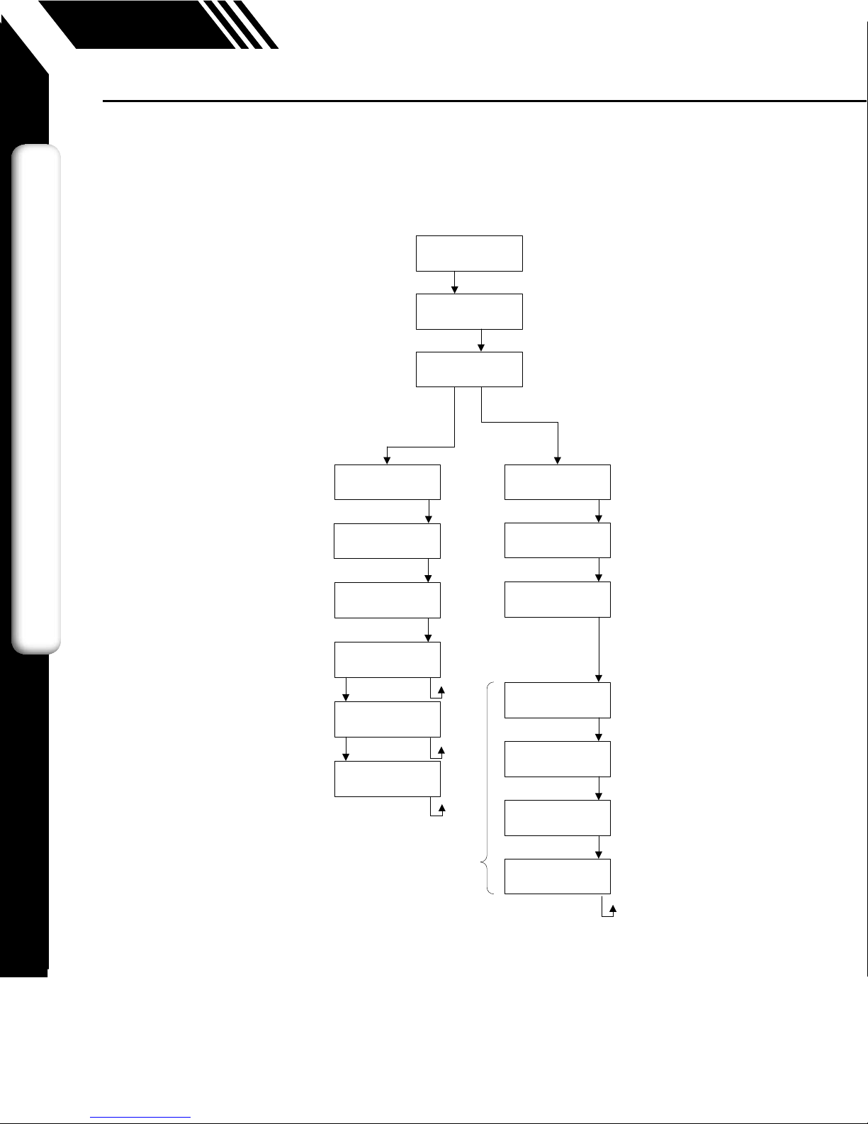
Main Menu

MAINMENU
I/OFLODSPEXIT
SETI/O
COM420EXIT
Comm=MODBUS
NXTOK
NONE
MODBUS
BACnet
mA=Flow
NXTOK
20mA=2345.6SCFM
CHGOK
4mA=0SCFM
CHGOK
Temp
Flow AnalogOutput
Baud=9600
NXTOK
Parity=NONE
NXTOK
Address=02
CHGOK
Modbus
only
1200
2400
4800
9600
19200
38400
57600
76800
115200
NONE
ODD
EVEN
01‐247
Entermenubyscrollingtodisplay4
andenteringthepassword
mAFault=Notuse
NXTOK
Notuse
3.6mA
21mA
Baud=9600
NXTOK
9600
19200
38400
57600
76800
115200 MAC_add=3
CHGOK
Max_master=127
CHGOK
ID=12345
CHGOK
Name=F‐5500
CHGOK
BACnet
only
SETI/O
PUL420EXIT
IfRS485hardwaredetected
Communication
OROR SETI/O
COMPUL420EXIT
Comm=HART
OK
Address=0
CHGOK
Ifpulse/alarmhardwaredetectedIfHARThardwaredetected/withlicense
0‐63
(p. 41)
(p. 42)
Display Menu, p. 9
Flow Menu 1, p. 7
Digital Output Menu, p. 6
11451 Belcher Road South, Largo, FL 33773 • USA • Tel +1 (727) 447-6140 • Fax +1 (727) 442-5699 • [email protected]
F-5500 Thermal Mass Flow Meter Manual 06/17 - 2030 / 107023 Page 5
Model F-5500
INTRODUCTION
Fig. 1.1: F-5500 Menu Tree - Main Menu
Main Menu
Introduction: Menu Trees

OUT=Pulse
NXTOK
Notused
Pulse
HiFloAlm
LoFloAlm
HiTempAlm
LoTempAlm
PulseOutput
U/PFEQEXIT
U/P=10
NXTOK
MaxFreq=1Hz
OK
MaxFlo=36000SCFM
CHGOK
HiFloAlm=500SCFM
CHGOK
LoFloAlm=100SCFM
CHGOK
HiTmpAlm=250°F
CHGOK
LoTmpAlm=10F
CHGOK
HighFlowAlarm
LowFlowAlarm
HighTempAlarm
LowTempAlarm
Pulse
OUT=HiFloAlm
NXTOK
OUT=LoFloAlm
NXTOK
OUT=HiTmpAlm
NXTOK
OUT=LoTmpAlm
NXTOK
SetI/O
PUL420EXIT
Alarmoutput
MAINMENU
I/OFLODSPEXIT
1
10
100
1000
ThePulsemenuitemswillonlyappear
formodelsthathaveorderedaPulse
outputoptionwiththeirF‐5500meter.
(p. 43)
(p. 45)
(See Flow Menu 2, p. 8, for more alarm settings)
(p. 43)
11451 Belcher Road South, Largo, FL 33773 • USA • Tel +1 (727) 447-6140 • Fax +1 (727) 442-5699 • [email protected]
F-5500 Thermal Mass Flow Meter Manual 06/17 - 2030 / 107023 Page 6
Model F-5500
DISCLAIMERINTRODUCTION
Fig. 1.2: F-5500 Menu Tree - Digital Output
Introduction: Menu Trees
Digital Output

FLOWMENU1
DGNUNTFM2EXIT
DIAGNOSTIC
SIMZEROEXIT
FloSim=0SCFM
CHGOK
TmpSim=0°F
CHGOK
ENABLESIM?
YESNO
FLOUNT=SCFH
NXTOK
SCFH
NM3/H
NM3/M
KG/H
KG/M
KG/S
LBS/H
LBS/M
LBS/S
NLPH
NLPM
MMSCFD
LBS/D
SLPM
NLPS
MSCFD
SM3/H
MT/H
NM3/D
MMSCFM
SCFD
MCFD
SM3/M
SM3/D
SCFM
TMPUNT=°F
NXTOK
DegF
DegC
TmpRef=60°F
CHGOK
PRESUNT=Psia
NXTOK
PresRef=14.73
CHGOK
mmHG
Psia
bara
STP
SimulateFlow?
YESNO
SimulateTemp?
YESNO
DNS=1.2323kg/m3
OK
MAINMENU
I/OFLODSPEXIT
(p. 56) (p. 49)
Flow Menu 2 Menu, p. 8
Zero CAL-CHECK
®
Menu, p. 10
11451 Belcher Road South, Largo, FL 33773 • USA • Tel +1 (727) 447-6140 • Fax +1 (727) 442-5699 • [email protected]
F-5500 Thermal Mass Flow Meter Manual 06/17 - 2030 / 107023 Page 7
Model F-5500
INTRODUCTION
Fig. 1.3: F-5500 Menu Tree - Flow Menu 1
Flow Menu 1
Introduction: Menu Trees

FLOWMENU2
SPCPRMEXIT
Kfact=0%
CHGOK
RESETCRC?
YESNO
Cutoff=12.5SCFM
CHGOK
Pipe_id=4.026In
CHGOK
Filter=0.8sec
CHGOK
Parameters
Flowcutoffinselectedunits
Pipeidininchesormm
FlowFilterinseconds
Min=0.8,max=10
HiFloAlm=0SCFH
CHGOK
LoFloAlm=0SCFH
CHGOK
HiTmpAlm=0°F
CHGOK
LoFloAlm=0°F
CHGOK
Thesealarmscanbeusedwithoutthedigitaloutputassignedtothe
alarm.
Ifthatisthecase,thealarmstatuswillonlybeshownonthedisplay,
throughserialcommunicationorF‐5000View.
Ifthedigitaloutputisassignedtoanalarm,changingthevalueherewill
changethatsetting.
Level2
RESTOREDATABASE
YESNO
SETNRT?
YESNO
AREYOUSURE?
YESNO
TotalResetOn
OK
Thismessagewillshowfor3seconds
beforereturningtotheFlow
Parameter2Menu.
WARNING:Oncethenon‐resettable
totalizerisactivated,itcannotbe
undone.
MAINMENU
I/OFLODSPEXIT
FLOWMENU1
DGNUNTFM2EXIT
On
Off
(p. 54)
(p. 51)
(p. 52)
11451 Belcher Road South, Largo, FL 33773 • USA • Tel +1 (727) 447-6140 • Fax +1 (727) 442-5699 • [email protected]
F-5500 Thermal Mass Flow Meter Manual 06/17 - 2030 / 107023 Page 8
Model F-5500
DISCLAIMERINTRODUCTION
Fig. 1.4: F-5500 Menu Tree - Flow Menu 2
Introduction: Menu Trees
Flow Menu 2

DISPLAY/PASSWORD
DSPPSWEXIT
DSP1L1=Florate
NXTOK
Florate
Total
Elps
Temp
Alarm
DSP1L2=Total
NXTOK
DSP2L1=Temp
NXTOK
DSP2L2=Elps
NXTOK
ALTERNATE=Off
NXTOK
On
Off
PASSWD=1234
CHGOK
Florate
Total
Elps
Temp
Alarm
Florate
Total
Elps
Temp
Alarm
Florate
Total
Elps
Temp
Alarm
Whenalternate
"ON",flashes
betweenthe2
displays
Display1
Line1
Display2
Line1
Display2
Line2
MAINMENU
I/OFLODSPEXIT
Display1
Line2
(p. 48)(p. 46)
i
11451 Belcher Road South, Largo, FL 33773 • USA • Tel +1 (727) 447-6140 • Fax +1 (727) 442-5699 • [email protected]
F-5500 Thermal Mass Flow Meter Manual 06/17 - 2030 / 107023 Page 9
Model F-5500
INTRODUCTION
Fig. 1.5: F-5500 Menu Tree - Display Menu
NOTE: All readings updated every second
•
Flo Rate = Flow rate of process gas
•
Total = Total flow of process gas
•
Elps = Elapsed time since reset of flow total
•
Temp = Temperature of process gas
•
Alarm = Notification of errors; diagnostic errors
Introduction: Menu Trees
Display Menu

DIAGNOSTICMENU
SIMZER0EXIT
ZEROCHKMENU
VEREXIT
ProcessZeroand
Stable?YESEXIT
VerifyingZERO
0.512T=123
ZERO=0.257
PassOK
Displaysthetest’s
countdowntimer
Displaysanumbervalue
duringtest
VERIFYZERO?
YESNO
ZERO=0.911
WarningOK
ZERO=2.321
FailOK
FLOWMENU1
DGNUNTFM2EXIT
MAINMENU
I/OFLODSPEXIT
(p. 60)
11451 Belcher Road South, Largo, FL 33773 • USA • Tel +1 (727) 447-6140 • Fax +1 (727) 442-5699 • [email protected]
F-5500 Thermal Mass Flow Meter Manual 06/17 - 2030 / 107023 Page 10
Model F-5500
DISCLAIMERINTRODUCTION
Fig. 1.6: F-5500 Menu Tree - Zero CAL-CHECK
®
Menu
Introduction: Menu Trees
Zero CAL-CHECK®
Menu

3124.6SCFH
csv=0.3432Volt
Enter:PressF1&F2atthesametime
PressF4toreturntonormalmode
Display10
Display11
Display12
Display13
Pulse=1234.5cnt
mA_420=234cnt
Display14
Elp=12.5HR
Stat(hex)=2800
Display15
Alarm=None
F‐5500V3.5d
Display16
Display17
MB_Sn=M23949234
BB_Sn=M23945524
Display18
MTR_Sn=N12345
SNS_Sn=23456
Display19
TmpHi=0.0F
TmpLo=0.0F
F2KeyF1Key
F3&F4pressedatthesametimewill
initiatea"Total"reset
Pwr_Cycl=24
Err_tot=0
FloHi=0.00SCFH
FloLo=0.00SCFH
ZRO=0.1
11451 Belcher Road South, Largo, FL 33773 • USA • Tel +1 (727) 447-6140 • Fax +1 (727) 442-5699 • [email protected]
F-5500 Thermal Mass Flow Meter Manual 06/17 - 2030 / 107023 Page 11
Model F-5500
INTRODUCTION
Introduction: Menu Trees
Engineering Display
Fig. 1.7: F-5500 Menu Tree - Engineering Display

Thank you for purchasing the Model F-5500 Thermal Gas Mass Flow Meter from
ONICON. The Model F-5500 is one of the most technically advanced flow meters
in the world. An extensive engineering effort has been invested to deliver advanced
features, accurate measurement performance and outstanding reliability.
This Instruction Manual contains the electrical and mechanical installation instructions
as well as details for programming, maintaining and troubleshooting the meter.
This manual is divided into the following sections: Introduction, Installation, Wiring,
Operation, Maintenance, Troubleshooting, Appendices, Glossary and Index.
Theory of Operation
The Model F-5500 is an innovative Thermal Mass Gas Flow Meter and Temperature
Transmitter. It is microprocessor-based and field programmable. The F-5500 thermal
sensor operates on the law that gases absorb heat. A heated sensor placed in an air
or gas stream transfers heat in proportion to the stream’s mass flow velocity. There
are two sensor elements. One sensor element detects the gas temperature and a
second element is maintained at a constant temperature above the gas temperature.
The energy applied to the heated sensor to maintain a constant temperature differential
(constant ∆ T) is directly proportional to the mass flow velocity. The F-5500 flow
meter maintains accurate flow measurement over a large temperature and pressure
range.
Mass Flow
The Model F-5500 measures mass flow; an advantage over other flow meters which
measure volumetric flow. Volumetric flow is incomplete because temperature and
pressure are unknown and must be measured separately. For example, the mass
flow of a gas depends on its temperature and pressure. As temperature and pressure
changes, the gas volume changes but not its mass. Therefore a device measuring
mass flow is independent of temperature and pressure changes. The Model F-5500
provides a direct measurement of gas flow in mass units (kg/hr, lb/hr), standard units
(SCFM, SLPM) or normal units (NM3/hr, NLPM) with no additional temperature or
pressure measurements required.
DDC-Sensor™Technology Description
The ONICON DDC-Sensor™ is a new state of the art sensor technology used in the
ONICON Model F-5500 Thermal Gas Flow Meter. The DDC-Sensor™, a Direct Digitally
Controlled sensor, is unlike other thermal flow sensors available on the market.
Instead of using traditional analog circuitry, the DDC-Sensor™ is interfaced directly to
the F-5500 microprocessor for more speed and programmability. The DDC-Sensor™
quickly and accurately responds to changes in process variables by utilizing the
microprocessor to determine mass flow rate, totalized flow, and temperature.
ONICON’s DDC-Sensor™ provides a technology platform for calculating accurate gas
correlations.
11451 Belcher Road South, Largo, FL 33773 • USA • Tel +1 (727) 447-6140 • Fax +1 (727) 442-5699 • [email protected]
F-5500 Thermal Mass Flow Meter Manual 06/17 - 2030 / 107023 Page 12
Model F-5500
DISCLAIMERINTRODUCTION
Introduction
Product
Description
Mass Flow
Welcome
DDC-Sensor™
Technology
Flow
Calibration

i
Flow Calibration
The ONICON Calibration Lab maintains instrument calibration data on every flow meter.
Calibration files include details on process conditions, customer gas, line size and
other information. All NIST-traceable equipment utilized for the calibration procedure is
identified on the Calibration Certificate, which is sent with every flow meter.
Calibration records include details on process conditions, calibration fluid, line size and
other information. All NIST-traceable equipment utilized for the calibration procedure is
identified, as is the calibration history of all reference equipment.
In addition to the Calibration Certificate, a certified flow table that correlates current
outputs with scaled units of flow is produced for each calibrated device.
I/O Description
The F-5500 features a galvanically isolated 4-20mA analog output with HART
communication option and a second output for pulse, RS485 Modbus RTU or BACnet
MS/TP. There is also a mini USB port for interfacing with a laptop or computer. The
4-20mA output can be configured for flow rate or process gas temperature and can be
scaled by the user. The pulse output can be used for pulse or alarm, is programmable
to represent flow rate and can be scaled for units per pulse at a maximum pulse output
frequency of 1 Hz.
F-5000 View™ interfaces to the USB port and is a free PC-based software program
that displays flow meter readings and permits flow meter configuration. The software
is available for download on the ONICON website. Industry standard communication
options are available including optional RS485 Modbus RTU, BACnet MS/TP, or HART.
NOTE: the latest version of the F-5000 View software is available for download at
http://www.onicon.com/F5500.html .
11451 Belcher Road South, Largo, FL 33773 • USA • Tel +1 (727) 447-6140 • Fax +1 (727) 442-5699 • [email protected]
F-5500 Thermal Mass Flow Meter Manual 06/17 - 2030 / 107023 Page 13
Model F-5500
INTRODUCTION
Introduction
I/O Description
Flow
Calibration

Standard I/O
4 -20mA Flow or Temperature
Pulse or Alarm
USB
(Free F-5000 View Software)
Outputs and Communications are
Galvanically Isolated
Selectable Output Options
RS485 Modbus RTU, BACnet MS/TP
HART Communication
Standard Digital Communications
12-28VDC Input Power
Display and
Conguration Panel
F1 F2 F3 F4
FLOW
AND
ENERGY
MEASUREMENT
F-5500 Functional Diagram
An on-board 2 line x 16 character backlit LCD display shows flow rate, total flow,
elapsed time, process gas temperature, and alarms. The display is also used in
conjunction with the User Interface for field configuration of flow meter settings such
as 4-20mA scaling, frequency output scaling, pipe area, zero flow cutoff, flow filtering
or dampening, display configurations, diagnostics, and alarm limits.
Fig. 1.8: F-5500 Function Diagram
11451 Belcher Road South, Largo, FL 33773 • USA • Tel +1 (727) 447-6140 • Fax +1 (727) 442-5699 • [email protected]
F-5500 Thermal Mass Flow Meter Manual 06/17 - 2030 / 107023 Page 14
Model F-5500
DISCLAIMERINTRODUCTION
Display
Introduction

1. Record inside diameter (ID). Ensure the actual
pipe ID matches the pipe ID shown on the
factory calibration certificate. If IDs do not
match, refer to p. 52.
2. Record upstream and downstream straight-pipe
requirements based on tables for insertion (p.
18) and inline (p. 26).
3. a. The Flow Direction Indicator must point in the
direction of flow.
b. The Indicator can also be used to change the
orientation of the housing for a better view of the
meter's display. Note that the 2 set screws must
be loosened before the housing will turn.
[refer to p. 21 for more information]
4. Ensure correct probe depth setting. If using 1 ½"
size pipe, please see note on p. 22.
5. Open the housing. If needed, the orientation of
display can be rotated in 90° increments for a
better view of the display in tight installations.
[refer to p. 28 for more information]
6. Ensure power wiring and 4-20mA wiring
properly connected
[refer to p. 30 - p. 32 for more information]
7. Verify you have the proper output signal wiring
setup based on model type (Pulse/Alarm or
communication protocol)
[refer to p. 33 - p. 35 for more information]
8. Power on the flow meter
9. Check the remaining flow meter settings by accessing the meter settings either through the front panel
of the display or by using the F-5000 View™ software tool. Record the settings in the spaces given for
items A - D on the following page.
Use the table and images below as a guide while using the worksheet on the next page to record your notes.
NOTE: Please read the entire Quick-start procedure before beginning installation.
INSIDE
DIAMETER (ID)
OUTER
DIAMETER (OD)
FLOW
DownstreamUpstream
INDICATOR:
- POINT IN DIRECTION
OF FLOW
- REMOVE TO ROTATE
HOUSING ±90º, ±180
º
- REPLACE INDICATOR
WHEN DONE
LOOSEN
HOUSING
WITH 2 FRONT
SET SCREWS,
RETIGHTEN
WHEN DONE
FLOW
FLOW
PIPE
0.73"
(18.5 mm)
L
C
F1 F2 F3 F4
ACCESS DISPLAY
BY UNSCREWING COVER
REMOVE SCREWS ON
DISPLAY TO ROTATE
DISPLAY ±180°
FLOW
AND
ENERGY
MEASUREMENT
(
-
) (+) (
-
) (+) (
-
) (+)
Power
12-28VDC
4-20mA Pulse
/Alarm
!
(
-
) (+) (
-
) (+) (
-
) (+)
Power
12-28VDC
4-20mA Pulse
/Alarm
!(
-
) (+)
Power
12-28VDC
4-20mA(
-
)
!
4-20mA(+)
Common
Tx/Rx(
-
)
Tx/Rx(+)
F1 F2 F3 F4
FLOW
AND
ENERGY
MEASUREMENT
Initializing...
11451 Belcher Road South, Largo, FL 33773 • USA • Tel +1 (727) 447-6140 • Fax +1 (727) 442-5699 • [email protected]
F-5500 Thermal Mass Flow Meter Manual 06/17 - 2030 / 107023 Page 15
Model F-5500
INTRODUCTION
Introduction: Quick Start Guide

Item to verify
Serial Number: Serial Number: Serial Number: Serial Number:
1. What is the Pipe ID? ID = ID = ID = ID =
2. Calculate the Upstream/
Downstream straight-pipe
requirements
UP =
DN =
UP =
DN =
UP =
DN =
UP =
DN =
3. a. Is the flow indicator
pointed in direction of flow?
b. Must the housing be
rotated for easy viewing?
Y / N
Y / N
Y / N
Y / N
Y / N
Y / N
Y / N
Y / N
4. Is the probe depth setting
correct?
Y / N Y / N Y / N Y / N
5. Have you rotated the display
for easier viewing?
Y / N Y / N Y / N Y / N
6. Verify proper power wiring
setup
7. Verify proper output wiring
setup
After powering on your meter, check items A - D below by accessing the meter settings either through the
front panel of the meter's display or by using the F-5000 View software tool.
A. Which flow units have been
set in meter? (SCFH, KG/H,
etc..)
B. Correct values for reference
temperature and pressure?
Y / N Y / N Y / N Y / N
C. Confirm the pipe ID listed
above same as "Pipe_id="
D. Verify the 4mA and 20mA
meter settings
4mA =
20mA =
4mA =
20mA =
4mA =
20mA =
4mA =
20mA =
Your Notes:
Before powering on your meter, use this worksheet to record your notes.
If you are experiencing any problems after completing this procedure, please call the ONICON Service
Department at 727-447-6140 to review this information.
Installation -
Model F-5500
Flow Meter
11451 Belcher Road South, Largo, FL 33773 • USA • Tel +1 (727) 447-6140 • Fax +1 (727) 442-5699 • [email protected]
F-5500 Thermal Mass Flow Meter Manual 06/17 - 2030 / 107023 Page 16
Model F-5500
DISCLAIMERINTRODUCTION
Introduction: Quick Start Guide Installation: General

Installation -
Model F-5500
Flow Meter
Scope
This section describes how to install the ONICON Model F-5500 Flow Meter and how
to get started:
1. Determine lateral position on the pipe
2. Sensor installation depth
3. Sensor orientation in relation to sensor length and direction of flow
4. Proper tightening of compression fitting for mounting meter
Installation procedures must be performed using a combination of the end user’s
best engineering practices, in compliance with local codes, and manufacturer’s
recommendations.
General Precautions
The following general precautions should be observed:
1. Exercise care when handling the flow meter to avoid damaging the probe, sensor
or enclosure.
2. The enclosure cover must be closed except during installation or configuration.
3. Mounting F-5500 in direct sunlight can cause the temperature inside the enclosure
to increase beyond design limits, resulting in failure of LCD display and reduced
component life. It is recommended that a sunshade be installed to avoid direct
sunlight (see maximum enclosure operating temperature specification in appendix).
4. Ensure the flow direction indicator/pointer for the meter is in line with the direction
of flow in the pipe.
5. Do not install the F-5500 enclosure near an igniter, igniter-controller or switching
equipment.
6. Do not install an external power supply in a cabinet containing an igniter controller
or switching equipment.
7. For accurate flow measurement: review flow meter placement instructions before
installation to ensure a proper flow profile in the pipe.
11451 Belcher Road South, Largo, FL 33773 • USA • Tel +1 (727) 447-6140 • Fax +1 (727) 442-5699 • [email protected]
F-5500 Thermal Mass Flow Meter Manual 06/17 - 2030 / 107023 Page 17
Model F-5500
INTRODUCTION
Installation: General

FLOW
Downstream
Proper
Flow
Prole
Upstream
Irregular Flow
Prole
Flow Direction
Indicator
F1 F2 F3 F4
F1 F2 F3 F4
Do not substitute threaded tees for
the welded branch outlet. Contact
ONICON if you need installation
hardware for threaded pipe.
i
i
Instructions for Insertion Flow Meter Lateral Placement
Install the Model F-5500 Insertion style flow meter so that it is far enough away from
bends in the pipe, obstructions, or changes in line sizes to ensure a consistent flow
profile. Review straight run requirements table on p. 21.
NOTE: The probe diameter is ¾".
Fig. 2.1: Upstream and Downstream Pipe IDs for Insertion Meters
Special Conditions of Use:
• Consult the manufacturer if dimensional information on the flameproof
joints is necessary.
• The flamepaths of the equipment are not intended to be repaired. Consult
the manufacturer if repair of the flamepath joints is necessary
• Follow the manufacturer's instructions to reduce the potential of an
electrostatic charging hazard.
NOTE: An irregular flow profile may affect sensor accuracy.
11451 Belcher Road South, Largo, FL 33773 • USA • Tel +1 (727) 447-6140 • Fax +1 (727) 442-5699 • [email protected]
F-5500 Thermal Mass Flow Meter Manual 06/17 - 2030 / 107023 Page 18
Model F-5500
INSTALLATION
Installation: Insertion Type
Insertion Flow
Meter Lateral
Placement
Installation
Hardware

1” Full Port Ball Valve
1” Close Nipple
1” Branch Outlet
Standard Installation
Kit for Steel Pipe
Minimum Hole Size = 7/8”
Must be centered
CLEARANCE
REQUIRED
FOR INSTALLATION
Typically
30” - 40”
depending on
pipe size and
height of valve
assembly.
i
Installation Hardware
ONICON F-5500 Insertion Thermal Mass Flow Meters employ a process adapter fitting
design that allows for insertion and removal, when necessary, without interrupting
flow and draining the pipe. To take advantage of this feature, the flow meter must be
installed through an isolation valve. The installation must allow for sufficient overhead
clearance to fully extract the meter, and a full 7/8" opening in the pipe wall is required
to clear the sensor head and allow for insertion. Make sure that your valves and fittings
are full port and at least 1" in actual internal diameter.
Fig. 2.2: Installation Requirements
CAUTION! ONICON insertion style flow meters must be installed through a valve
assembly. Failure to do so negates the ability to remove the meter without shutting
down and draining the system. It will also result in an excessive amount of stem
protruding from the pipe. Excessive stem lengths unnecessarily expose the meter to
incidental damage.
NOTE: Flow meters installed through oversized access holes will be subjected to
undesirable turbulence that may affect the accuracy of the meter.
Flow Conditioners
Flow conditioners may be required when an insufficient straight run of pipe is available
upstream of the proposed sensor location. ONICON provides flow conditioners as an
optional accessory.
11451 Belcher Road South, Largo, FL 33773 • USA • Tel +1 (727) 447-6140 • Fax +1 (727) 442-5699 • [email protected]
F-5500 Thermal Mass Flow Meter Manual 06/17 - 2030 / 107023 Page 19
Model F-5500
INSTALLATION
Installation: Insertion Type
Installation
Hardware
Flow
Conditioners

Flow
80% 20%
Available Straight Run*
* See following page for straight run requirements
Flow
80% 20%
Available Straight Run*
• For 1½” and larger diameter pipes
• Install in vertical or horizontal pipe
• For horizontal pipe position meter
anywhere in upper 180°
CLEARANCE
REQUIRED
FOR INSTALLATION
30” - 36”
Depending on
pipe size
Vertical pipe position
Flow
Minumum upstream
straight run distance
with conditioner
Minumum
downstream
straight run
distance
Minumum upstream
straight run distance
without conditioner
A
Optional
Flow Conditioner
Fig. 2.3: Placement of Optional Flow Conditioners in Pipe
ONICON flow conditioners are designed to be installed between two flanges (provided
by installer) that are located a specific distance upstream of the flow sensor. The use
of flow conditioners significantly reduces the upstream straight pipe length requirement
for flow sensor. The size of the flow conditioner must match the pipe size. Contact
ONICON for Schedule 80 flow conditioners.
Schedule 40 Flow Conditioners
Nom. Dia. Dimension A
1½" 6.00"
2" 6.00"
2½" 9.00"
3" 9.00"
4" 9.00"
6" 12.00"
11451 Belcher Road South, Largo, FL 33773 • USA • Tel +1 (727) 447-6140 • Fax +1 (727) 442-5699 • [email protected]
F-5500 Thermal Mass Flow Meter Manual 06/17 - 2030 / 107023 Page 20
Model F-5500
INSTALLATION
Installation: Insertion Type
Flow
Conditioners
Table of contents
Other Onicon Accessories manuals