15
15
Instructions
10. Insert the threaded rod (3) as an axle into the axle carrier
(f). Add wheels (15) to both sides of the axle (j) as de-
scribed in step 7.
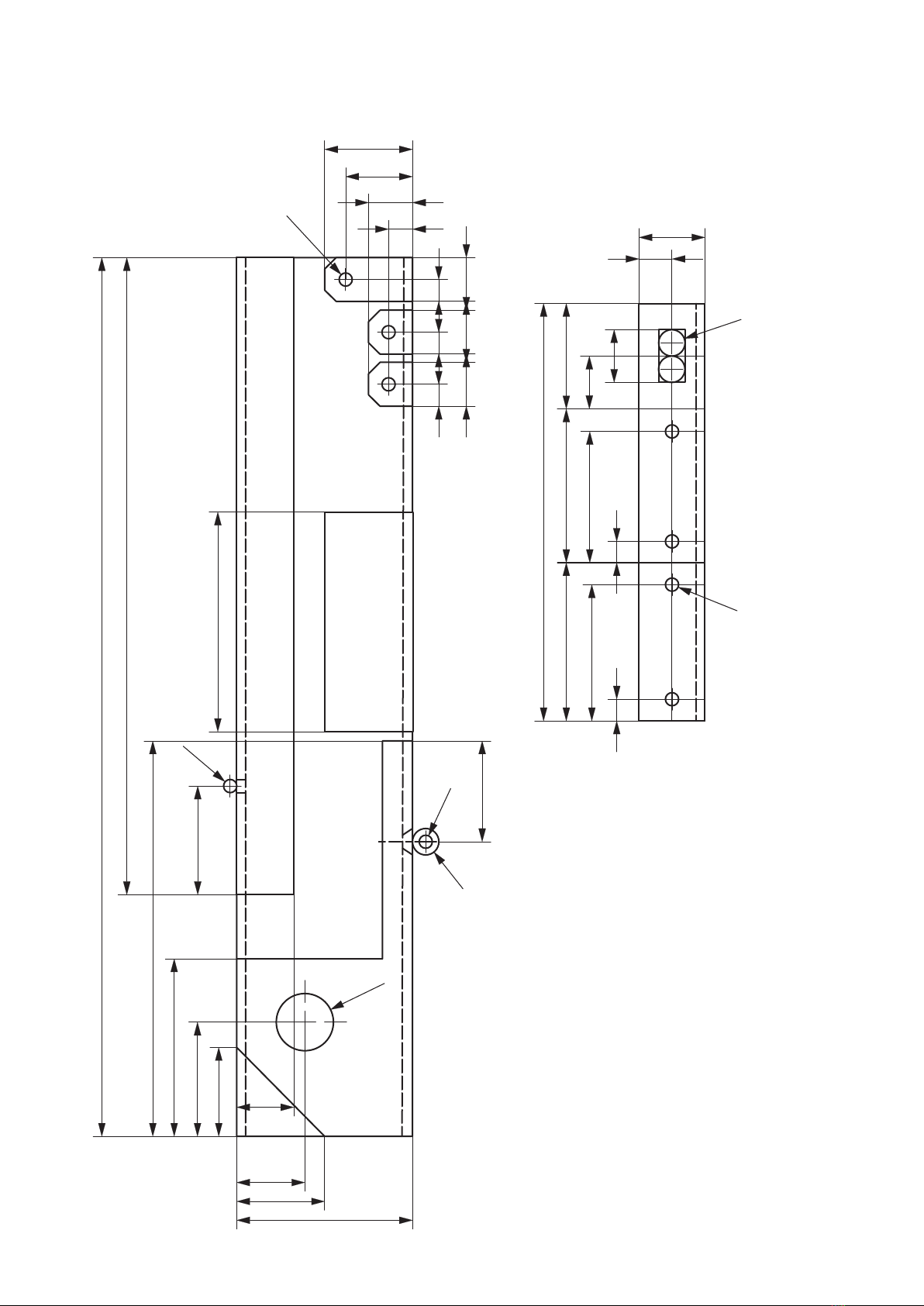
Drill a ø4mm hole
11. Drill a ø4mm hole through the centre of part (i) in order
to feed the cables through.
Cabling:
Wiring diagram:
12. Solder the resistor (12) to the outer switch connec-
tor (11). Strip the insulation from the red battery
clip cable (10), tin it, feed it upwards through the
drill hole in part (h) and solder it to the centre
switch connector (11). Strip the insulation from the
black battery clip cable, tin it and feed it upwards
through the drill hole in part (h). Solder the anodes
(long leg) of the red LEDs together. Then solder the
two cathodes (short leg) together. Do the same
with the two yellow LEDs. Cut o approx. 180mm
wire (red, 8) strip the insulation from both sides
and tin. Feed one end upwards through the drill
hole in part (h). Connect the other end to the two
anodes from the red LEDs (13). Cut o approx.
150mm wire (red, 8) strip the insulation from both
sides and tin. Again feed one end through the drill
hole, twist it with the end of the 180mm wire and
solder to the resistor (12). Connect the other end to
the anodes of the yellow LEDs (14).
Cut o approx. 180mm of black wire (9) strip the
insulation and tin. Feed one end upwards through
the drill hole in part (h) and twist it with the end of
the black cable from the battery clip (10). Solder
the other end to the two cathodes from the red
LED (13). Cut o approx. 150mm of black wire (9),
strip the insulation, tin, feed upwards through the
drilled hole, twist s well with the black cable from
the battery clip (10) and solder the three black cab-
les together. Connect the other end to the catho-
des from the yellow LEDs (14). Connect the battery
to the battery clip and insert the battery into its
compartment (part c).
Note: Do not touch any PVC parts with the solde-
ring iron when soldering!
LED red LED
yellow
Resistance 180 ohm
red black
180mm
black
150mm
red
180mm
red
150mm