manuals.online logo
Brands
  1. Home
  2. •
  3. Brands
  4. •
  5. Optex
  6. •
  7. Media Converter
  8. •
  9. Optex REDWALL PIE-1 User manual

Optex REDWALL PIE-1 User manual

PoE IP Encoder
PIE-1
PoE IP Encoder
PIE-1
INSTALLATION INSTRUCTIONS
( for SIP series and RLS series )
No.5919420
▪ PIE-1 changes analog relay output signals (N.C.) to
original ASCII code.
▪ PIE-1 can supply power to detector using a PoE hub
or switch.
▪ Follow all cautions and instructions in this manual
before installation.
▪ Keep this manual after installation so that you can
read when necessary.
▪ Remember the meanings of “Warning” and
“Caution” below to use the product safely.
If you ignore a caution, the user or other
people may be injured or the product or
something around it may be damaged.
If you ignore a warning, the user or other
people may be injured or dead.
▪ Do not repair, dismantle or modify the product
yourself.
▪ Do not touch the product with a wet hand.
▪ Be careful not to damage other interior wiring when
installing or wiring the product.
▪ Power off the product immediately if smoke, odor or
strange sound emits from the product.
▪ Do not install the product in an extremely moist place
such as a bathroom or a place where the product
may be wet.
▪ Insert the connectors securely when wiring.
Caution
■No. 6-32 UNC screw (5/8 inch), 6 pcs
■Alarm 10-pin cable (26cm)
■Power 2-pin cable (26cm)
■Alarm 6-pin cable (10cm)
■Alarm 4-pin cable (10cm)
■Power 2-pin cable (10cm)
■Main unit of PIE-1
SAFETY PRECAUTION
FEATURES
Connectors
WarningWarning
Warning: This is a class A product. In a domestic
environment this product may cause radio interference
in which case the user may be required to take
adequate measures. (EN55022)
CE Statement
Warning
Caution
■SIP mounting plate
for Gang Box
■ Gasket sheet
for Gang Box
PARTS IDENTIFICATION
1
Ethernet connector for PoE
Ethernet connector for detector
24VDC Power output connector
12VDC Power output connector
Alarm input connector
▪ Be sure to use the attached cables.
▪ Do not use 12V and 24V power sources at the same time.
Caution
(1) Prepare an appropriate Dual Gang Box.
(2) Using an Allen key, detach the SIP base from the SIP main unit.
(1) Plug the alarm 10-pin cable to
PIE-1.
(2) Plug the power 2-pin cable to
PIE-1. Use the 12VDC connector.
Note: When using an optional heating
unit, use the 24VDC connector.
(3) Set the Selector switch of PIE-1
to the left.
(4) Plug a CAT5 cable to the
Ethernet connector for PoE.
(5) Place the PIE-1 into the Dual
Gang Box.
(1) Take off a rectangular gasket
and two round gasket from the
gasket sheet.
(2) Apply the rectangular gasket on
the SIP mounting plate.
(3) Apply the two round gaskets in
layers around the round hole of
the SIP mounting plate.
(1) Pass the alarm 10-pin
cable and the power
2-pin cable through
the hole.
(2) Using four screws,
mount the SIP
mounting plate to the
Gang Box.
(3) Pass the cables
through the hole on
the back of the SIP
base.
(4) Using two screws,
mount the SIP base to
the SIP mounting plate
on the Gang Box.
Step 1
Step 3Step 2 Step 4
Step 6Step 5 Step 7
Mount the SIP
main unit onto
the SIP base.
(1) Connect the power and alarm
cables.
(2) If cables are too long, put the
extra portions into the Gang Box.
When the PIE-1 unit is accommodated not in Gang box, mount it in weather proof box or cabinet to avoid moisture.
Plug the alarm 6-pin cable, the
alarm 4-pin cable and the power
2-pin cable to terminals on the SIP
base.
CONNECT PIE-1 TO THE SIP MAIN UNIT
2
Warning
Note: Refer to the
Connection
Table.
Step 3
Step 4
Step 5
Step 6
Step 2
(1) (2)
(3)
(4)
Do not use
An example of IP address settings
IP Address
Subnet Mask
: 192.168.0.1
: 255.255.255.0
The default settings of PIE-1 are as follows.
  IP Address: 192.168.0.126
  Subnet Mask: 255.255.255.0
  Defoult Gateway: 0.0.0.0
(1) Before using PIE-1, set the IP addresses of PIE-1
and the computer in the following procedure.
1.Set the local area connection.
7.Click “Overview”button. Confirm the settings in
the Overview screen.
6.After changing settings. Click “Save Config”
button.
Download the detailed instructions at our site.
(
http://www.optex.co.jp/e/redwall/download/index.html)
If you forget the IP address you have set, reset it to
obtain the default IP address in the following procedure.
2.Using Internet Explorer, access the site below.
(http://192.168.0.126/)
3.Enter the user ID and the password below.
User ID: PIE-1
Password: OPTEX
4.Change the IP address if necessary.
5.Select the detector you have connected.
(2) Confirm the output of the Event Code, and set
VMS/NVR.
(3) After setting VMS/NVR, conduct a walk test.
AFTER INSTALLATION
3
RESETTING
4
1.Pull off the cable connected to the Ethernet
connector for PoE.
PIE-1 turns off.
2.While pressing the
RESET button,
connect the cable to
the Ethernet
connector for PoE
again. PIE-1 turns on.
3.Keep pressing the RESET button until the
green and yellow LEDs both go off. (They go off
within ten seconds.)
4.Release the RESET button. The software
restarts, and PIE-1 obtains the default IP
address.
Alarm 6-pin cable
SIP-404, 4010, 3020
SIP-5030, 404/5, 4010/5, 3020/5
SIP-100
Model name
Orange pair Yellow pair Green pair Blue pair Purple pair Red Black
Far
-
- -
Near Creep Tamper Trouble (+) (-)
Alarm Creep Tamper Trouble (+) (-)
Alarm Tamper Trouble (+) (-)
Alarm 4-pin cable Power 2-pin cable
PIE-1 CONNECTION TABLE FOR SIP SERIES
Be sure to insulate the cables you are not using.
Caution
OPTEX CO., LTD. (JAPAN) (ISO 9001 Certified) (ISO 14001 Certified) URL:http://www.optex.co.jp/e/
5-8-12 Ogoto Otsu Shiga 520-0101 JAPAN TEL:+81-77-579-8670 FAX:+81-77-579-8190
OPTEX INCORPORATED (USA) TEL:+1-909-993-5770 Tech:(800)966-7839  URL:http://www.optexamerica.com/
OPTEX SECURITY SAS (FRANCE) TEL:+33-437-55-50-50 URL:http://www.optex-security.com/
OPTEX (EUROPE) LTD. (UK) TEL:+44-1628-631000 URL:http://www.optexeurope.com/
OPTEX SECURITY Sp. z o. o. (POLAND) TEL:+48-22-598-06-55 URL:http://www.optex.com.pl/
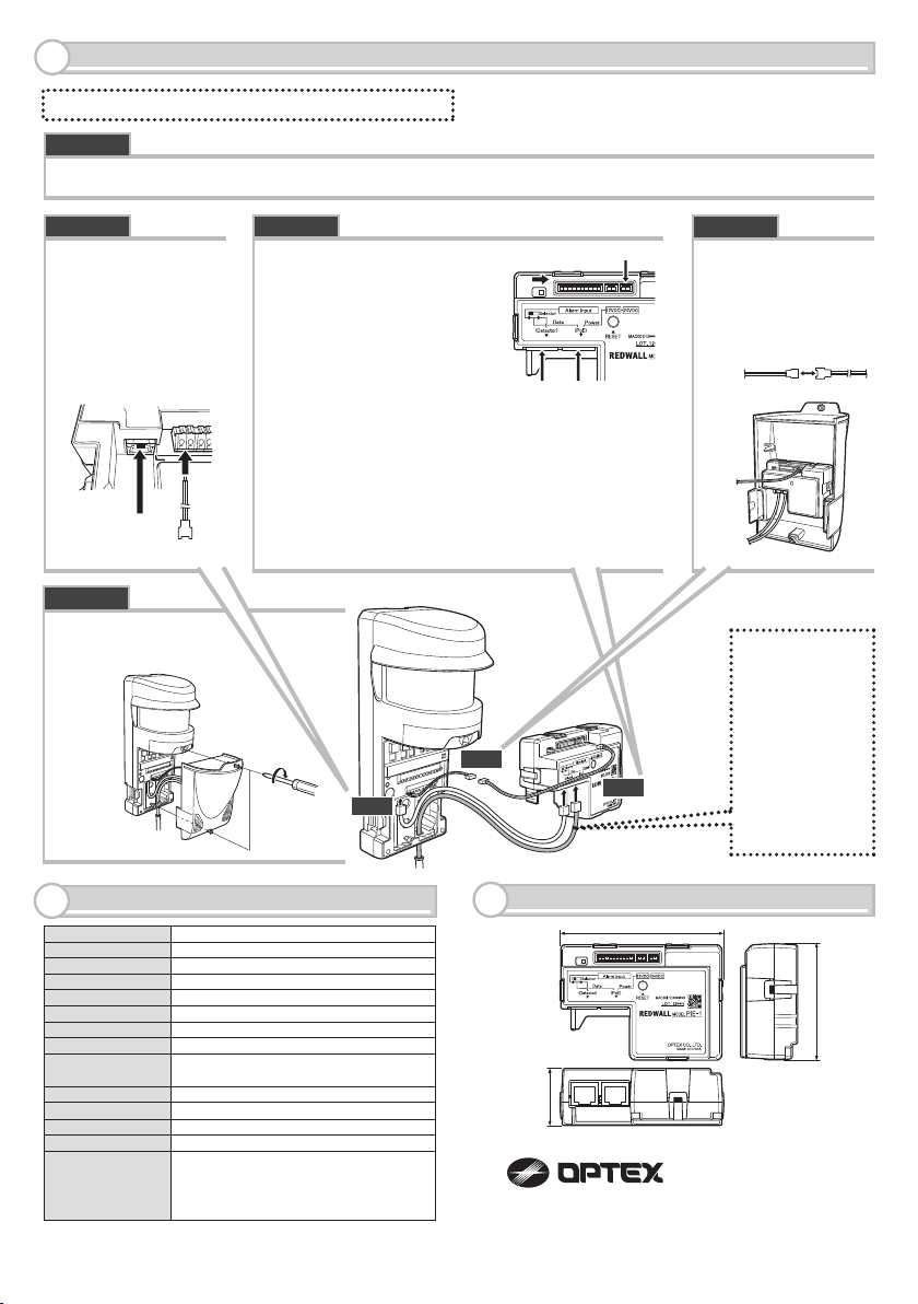
67.5 (2.66)
33.0 (1.30)
94.7 (3.73)
Step 2
Step 3
Step 4
PoE (IEEE802.3af/at compliant)
24VDC 800mA max, 12VDC 50mA max
5 input for dry contacts (N.C. only)
Outdoor (Inside of the waterproof case)
Redwall event code (UDP/TCP)
-40 to +60°C (-40 to + 140°F)
95% RH. max
Green light is ON when the power is supplied by PoE
Yellow light blinks during communication
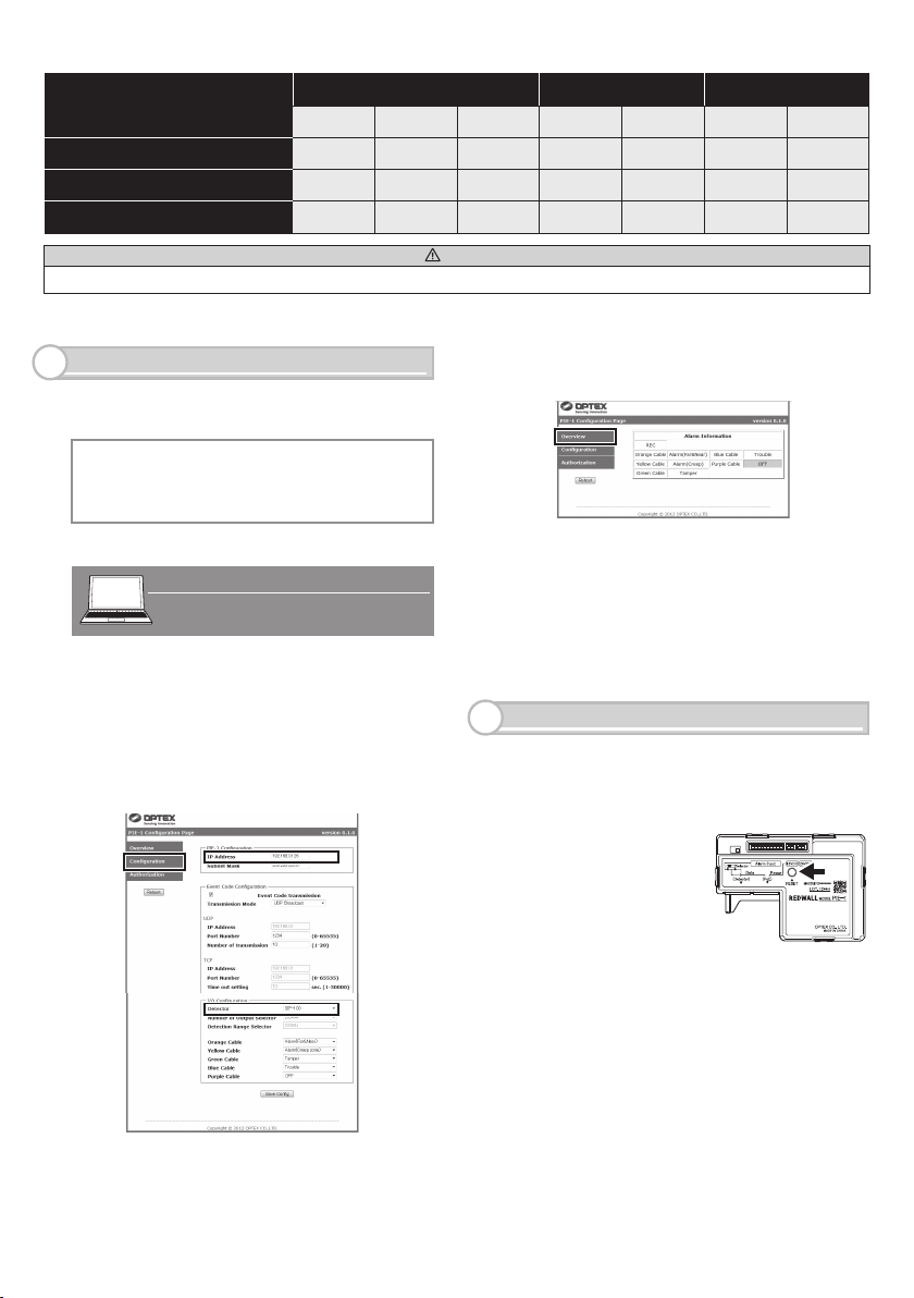
Use web browser
67.5mm x 94.7mm x 33.0mm (2.66” x 3.73” x 1.30”)
270g (8.8 oz:Including all parts) Main unit : 90g(3.2 oz)
IPv4, ARP, UDP, TCP, ICMP, HTTP
Power supply
Unit : mm (inch)
Power output
Signal input
Place of use
Alarm output
Operating temperature
Operating humidity
Operation LED
(Normal)
Operation LED
(When communicating)
Function setting
Dimension
Weight
Supported protocols
Accessories
SPECIFICATIONS
6
DIMENSIONS
7
Alarm 10-pin cable (26cm), Alarm 6-pin cable
(10cm), Alarm 4-pin cable (10cm), Power 2-pin
cable (26cm), Power 2-pin cable (10cm), SIP
mounting plate for Gang Box, Gasket sheet for
Gang Box, No. 6-32 UNC screw (5/8 inch) x 6
*Required power less than 12.95W, can use the PoE Hub.
Required power less than 25.5W, can use the PoE Plus Hub.
*Specifications may be modified without prior notice.
*
(1) Using a screwdriver, remove the cover from the RLS main unit.
(1) Plug the power
2-pin cable to the
RLS main unit.
(2) Plug the CAT5
cable to Ethernet
connector of the
RLS main unit.
(1) Plug the power 2-pin
cable to PIE-1.Use the
24VDC connector.
(2) Set the Selector switch of
PIE-1 to the right.
(3) Lead a CAT5e cable from
the switching hub into the
RLS main unit through a
hole on its bottom.
(4) Plug the CAT5e cable to the Ethernet connector
for PoE of PIE-1.
(5) Plug the CAT5 cable, already connected to the
RLS main unit (Step 2(2)), to the Ethernet
connector for detector of PIE-1.
(1) Connect the power
cables.
(2) Place PIE-1 into
the cover.
Step 1
Step 3Step 2 Step 4
(1) Mount the cover
onto the RLS main
unit.
Step 5
CONNECT PIE-1 TO THE RLS UNIT
5
Note>>
When use
REDSCAN series,
use CAT5e or
greater cable
between the PIE-1
unit and the PoE
Hub.
*Required power
less than 25.5W,
can use the PoE
Plus Hub.
Note>> Use a switch or hub conforming to IEEE802at type2.
(1)
(1)
(1)
(2)
(2)
(2)
(5) (4)

Other Optex Media Converter manuals

Optex LINK-BT1 C User manual

Optex

Optex LINK-BT1 C User manual

Optex Smartline Series User manual

Optex

Optex Smartline Series User manual

Popular Media Converter manuals by other brands

arcutronix EDX100 user guide

arcutronix

arcutronix EDX100 user guide

CTC Union IMC-1000C Quick installation guide

CTC Union

CTC Union IMC-1000C Quick installation guide

Timewave DSP-D300 manual

Timewave

Timewave DSP-D300 manual

Rosemount 333 HART Tri-Loop product manual

Rosemount

Rosemount 333 HART Tri-Loop product manual

Danfoss VLT AutomationDrive FC 300 operating instructions

Danfoss

Danfoss VLT AutomationDrive FC 300 operating instructions

SKYDANCE D4-XE quick start guide

SKYDANCE

SKYDANCE D4-XE quick start guide

Aetina MSB-DP24H user manual

Aetina

Aetina MSB-DP24H user manual

Fostex 3045 owner's manual

Fostex

Fostex 3045 owner's manual

Wintop 10/100M user manual

Wintop

Wintop 10/100M user manual

Speaka Professional SP-5587128 operating instructions

Speaka Professional

Speaka Professional SP-5587128 operating instructions

Lika HSC59 quick start guide

Lika

Lika HSC59 quick start guide

dunkermotoren AMETEK ServoTube 11 Module user guide

dunkermotoren

dunkermotoren AMETEK ServoTube 11 Module user guide

MediaSonic MS9100 installation guide

MediaSonic

MediaSonic MS9100 installation guide

Link HD & SDI Frame Synchronizer HFS-975 Specification sheet

Link

Link HD & SDI Frame Synchronizer HFS-975 Specification sheet

Crystalio VPS-2300 user guide

Crystalio

Crystalio VPS-2300 user guide

LINK-MI LM-DA03 user manual

LINK-MI

LINK-MI LM-DA03 user manual

Magewell Pro Convert AES67 user manual

Magewell

Magewell Pro Convert AES67 user manual

BÄSSGEN QUATRIX manual

BÄSSGEN

BÄSSGEN QUATRIX manual

manuals.online logo
manuals.online logoBrands
  • About & Mission
  • Contact us
  • Privacy Policy
  • Terms and Conditions

Copyright 2025 Manuals.Online. All Rights Reserved.