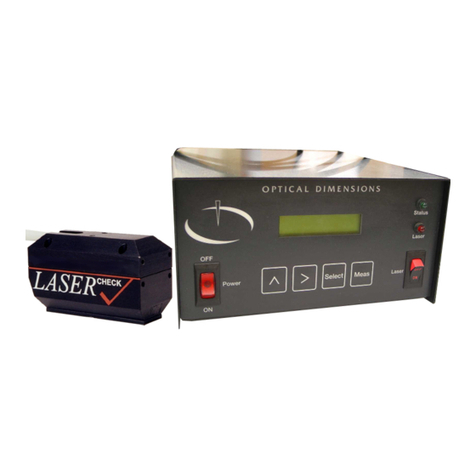
Optical dimensions Lasercheck 6212C User manual

OPTICAL DIMENSIONS™
2973 Harbor Blvd, #665, Costa Mesa, CA 92626
Phone: (831) 287-0495
i n f o @ o p t i c a - l d i m e n s i o n s . c o m
w w w . o p t i c a l - d i m e n s i o n s . c o m
™
Operations and Specification Manual for the
Lasercheck 6212C System
Manual Revision 15.22 Rev 07-19
© Optical Dimensions
and Optical D i m e n s i o n s are Registered Trademarks of Optical
Dimensions. The information in this document is provided as an aid in the
Assembly, Diagnostics, and Operation of the Lasercheck Gage, Components, and Accessories
and is not to be used otherwise or reproduced without written consent of Optical Dimensions.
The Lasercheck gage is patented technology protected under US Patent Number 5,608,527.
LASER
CHECK

OPTICAL DIMENSIONS™
2973 Harbor Blvd, #665, Costa Mesa, CA 92626
Phone: (831) 287-0495
i n f o @ o p t i c a - l d i m e n s i o n s . c o m
w w w . o p t i c a l - d i m e n s i o n s . c o m
™
Contents
Operations and Specification Manual for the .......................................................................................................................i
Lasercheck 6212C System .....................................................................................................................................................i
Manual Revision 15.22 Rev 07-19 ............................................................................................................................................ i
© Optical Dimensions ..............................................................................................................................................................i
PERFORMANCE SPECIFICATIONS..........................................................................................................................................1
Other Features.........................................................................................................................................................................1
SAFETY.................................................................................................................................................................................2
Electrical ..................................................................................................................................................................................2
Laser ........................................................................................................................................................................................2
WARRANTY OVERVIEW .......................................................................................................................................................3
LIMITATION OF WARRANTY ....................................................................................................................................................3
Contact Optical Dimensions customer service for shipping instructions: ................................................................................3
MAINTENANCE ....................................................................................................................................................................4
Cleaning the Windows.............................................................................................................................................................4
Assistance................................................................................................................................................................................4
INTRODUCTION TO LASERCHECK .........................................................................................................................................5
Overview..................................................................................................................................................................................5
Setting up the Instrument....................................................................................................................................................6
Unpacking Lasercheck.............................................................................................................................................................6
Basic Connections....................................................................................................................................................................7
J1 and J2 Communication Connections ..............................................................................................................................7
J3 and J4 Power Connections..............................................................................................................................................8
J7 IO (Input / Output) Connections.....................................................................................................................................8
Basic Operation ...................................................................................................................................................................9
Software Setup ........................................................................................................................................................................9
To Install Lasercheck Software from Windows...................................................................................................................9

OPTICAL DIMENSIONS™
2973 Harbor Blvd, #665, Costa Mesa, CA 92626
Phone: (831) 287-0495
i n f o @ o p t i c a - l d i m e n s i o n s . c o m
w w w . o p t i c a l - d i m e n s i o n s . c o m
™
Running the System using Lasercheck Windows Software.................................................................................................9
Comm. port Baud rate....................................................................................................................................................9
Turn on Lasercheck Windows Software .......................................................................................................................10
Set Comm Port on computer........................................................................................................................................10
Review or Create Lasercheck Setup Files on computer................................................................................................11
Perform Measurements ...............................................................................................................................................12
Physical Mounting .................................................................................................................................................................15
Manual Operation.............................................................................................................................................................15
Automated Operation.......................................................................................................................................................15
Numerous Continuous Measurements ........................................................................................................................16
Individual Parts / Parts Inspection................................................................................................................................17
Positioning Prox Sensors on Conveyor for Automated Inspection ..........................................................................17
Setup and Alignment.............................................................................................................................................................18
Message Type 15 ..............................................................................................................................................................18
Sample Setup and Alignment Aid from Message Type 15............................................................................................18
Performing Roughness Measurements .................................................................................................................................20
Message Type 02 ..............................................................................................................................................................20
Rough and Smooth Ra Value ........................................................................................................................................20
Common Error Codes ...................................................................................................................................................20
Max Detector................................................................................................................................................................20
Recommended Tests and Diagnostics ..............................................................................................................................20
Negative Ra Value.........................................................................................................................................................20
Low sum_voltages and “lv” Error Code ........................................................................................................................20
Appendix A –Lasercheck Alignment Principles and Procedures.........................................................................................22
How Does Lasercheck Work? ................................................................................................................................................22
Alignment ..............................................................................................................................................................................23
Vertical..............................................................................................................................................................................23
Vertical Alignment Base plate ......................................................................................................................................24
Horizontal .........................................................................................................................................................................25
Cylindrical Surface Measurement Alignment Fixture...................................................................................................26
Bore ID Surface Measurement Alignment Fixture........................................................................................................27
Directional / Rotational.....................................................................................................................................................27
Custom Shapes and Fixturing ................................................................................................................................................28
3-Dimensional Shapes.......................................................................................................................................................28
Small Surfaces...................................................................................................................................................................29
Checking Alignment Using the Lasercheck Diagnostics Option...........................................................................................30
1) Prepare Software to Receive Alignment Measurement...........................................................................................30

OPTICAL DIMENSIONS™
2973 Harbor Blvd, #665, Costa Mesa, CA 92626
Phone: (831) 287-0495
i n f o @ o p t i c a - l d i m e n s i o n s . c o m
w w w . o p t i c a l - d i m e n s i o n s . c o m
™
2) Prepare Sample and Fixture .....................................................................................................................................30
3) Perform Measurement.............................................................................................................................................30
4) Save Measurement Data for Input to Lasercheck Align Graph.xls Spreadsheet ......................................................31
5) Graphing the Lasercheck Data Measurements in Excel Spreadsheet ......................................................................31
5) Determining Alignment using the Lasercheck Alignment Graph Excel Spreadsheet ...............................................32
Vertical Alignment....................................................................................................................................................32
Horizontal Alignment ...............................................................................................................................................32
Notes to Using the Lasercheck Diagnostics Option for Alignment...............................................................................33
Vertical Alignment....................................................................................................................................................33
Horizontal Alignment ...............................................................................................................................................34
Recommended Alignment Diagnostics..................................................................................................................................34
Verifying Alignment Procedures .......................................................................................................................................34
Set Head Close to Correct Position...............................................................................................................................34
Align Horizontally .........................................................................................................................................................34
Align Vertically..............................................................................................................................................................34
Verify Alignment...........................................................................................................................................................35
Appendix B –Mounting/Fixturing Lasercheck....................................................................................................................36
Existing Mounting Holes on Lasercheck Sensor.....................................................................................................................37
Appendix C - Calibration Procedures..................................................................................................................................38
Theory - Measurement and Calibration ................................................................................................................................38
Measurement of Roughness.............................................................................................................................................38
Requirement for Calibration of Lasercheck to Specific Machining Operation..................................................................39
Base Calibration ....................................................................................................................................................................40
Overview of Calibration Process............................................................................................................................................40
Appendix D –Communication Protocol .............................................................................................................................41
Message Types: .....................................................................................................................................................................42
@02 Request Ra Value......................................................................................................................................................42
Response Details: .........................................................................................................................................................42
@03 Request Ra Value......................................................................................................................................................43
Response Details: .........................................................................................................................................................44
@04#<cr-lf> Specular Values Request ..............................................................................................................................45
@05 Request Ra Value......................................................................................................................................................45
Response Details: .........................................................................................................................................................46
@07<cr-lf> Set/Query Failed Part Operation...................................................................................................................46
Set xx subfunctions.......................................................................................................................................................47
@10#<cr-lf> Laser on Voltages: used to request just laser on voltages. Only for testing purposes................................47
@11#<cr-lf> Convert Light & subtract Dark, correct and send processed voltages .........................................................47

OPTICAL DIMENSIONS™
2973 Harbor Blvd, #665, Costa Mesa, CA 92626
Phone: (831) 287-0495
i n f o @ o p t i c a - l d i m e n s i o n s . c o m
w w w . o p t i c a l - d i m e n s i o n s . c o m
™
@15<cr-lf> Combine Cmd 11, 02, and 04 .........................................................................................................................48
@20,xx#<cr-lf>, Set/Query baud rate...............................................................................................................................48
@21#<cr-lf>, Query Revision Number..............................................................................................................................48
@22,xx,vvv#<cr-lf> Set/Query Configuration Values........................................................................................................49
Set Values .....................................................................................................................................................................49
Query Values ................................................................................................................................................................49
@23,xxxxx#<cr-lf>, Set/Query Head Serial Number .........................................................................................................50
@26,b,xxx.xxV#<cr-lf>, Set/Query resistor values............................................................................................................50
@29,xx,vv.vv#<cr-lf> Set/Query Ra Calibration Values ....................................................................................................51
Appendix E –Wiring and Dimensions American and Metric Versions ................................................................................52

6212C Manual Version 15_22 Rev 07-19.docx
Page 1 of 53
PERFORMANCE SPECIFICATIONS
Measurement / Detection Method
Angle resolved laser scattering
Measurement speed
Single measurement in < 0.5 seconds
Measurement range
0.5 µinch to 40 µinch / 0.0125 µm to 1.0 µm
Repeatability
± 3.0% of measured value
Spot size (area-measured)
5 mm X 1 mm
Environmental considerations (temperature / humidity):
Operating
-10º C to +55º C / 10% to 90% RH
Storage
-40º C to +80º C / 1% to 99% RH
Power requirements
7 to 18 VDC
Other Features
Factory Calibrated to Ra Ground Surface Standards
Works on any material/color (rubber, glass, steel, etc.)
ASCII format Serial Communication via RS232 Interface
Ability for external triggering / remote control

6212C Manual Version 15_22 Rev 07-19.docx
Page 2 of 53
SAFETY
Electrical
Lasercheck has been designed as a sealed and enclosed system. Voltages to operate the measurement sensor
are low (0 to +5 Volts) to minimize shock hazard.
Laser
The laser used in Lasercheck is a class II laser device. Class II lasers are not considered hazardous to the skin but
are considered a “chronic viewing hazard”. Users should not stare directly into the beam or directly into the
beam reflected off a smooth specular surface. The ends of the Lasercheck measurement sensor have “Caution”
and “Avoid Exposure” labels to remind the operator to avoid exposure to the radiation. The sensor also has
“Identification” and “Certification” labels. The Lasercheck control unit also has "Identification” and
“Certification” labels. Reproductions of these labels are shown below.
Caution –use of controls or adjustments or performance or procedures other than those specified herein may
result in hazardous radiation exposure.
The measurement sensor emits a red visible (650-nm) laser beam pulsing at a 10 to 50 Hz. Each “pulse” contains
as much as 90 microjoules of energy. Pulses can be as short as a 5 millisecond interval, with 20 microsecond rise
and fall times. Maximum “peak” power can be as high as 2.0 milliwatts. Average maximum power being
emitted from the laser can be as high as 900 microwatts. Once the beam strikes the measurement surface, the
laser energy is reflected back into the Lasercheck detection system. However, multiple reflections and stray
light may exit from between the sensor and measurement surface and care should be taken to avoid direct eye
exposure to the radiation.
Typical Laser Identification and Warning Labels
Mfg Date:
Serial #
Complies with 21 CFR
1040.10 and 1040.11
U.S. Patent No. 5,608,527
Model 6212
TM
CAUTION
DO NOT STARE INTO BEAM
LASER RADIATION
CLASS II LASER PRODUCT
650 nm –0.9 mW MAXIMUM
AVERAGE OUTPUT
AVOID EXPOSURE
Laser Radiation Emitted
From This Aperture

6212C Manual Version 15_22 Rev 07-19.docx
Page 3 of 53
WARRANTY OVERVIEW
Optical Dimensions certifies that the Lasercheck surface roughness measurement system meets specifications.
The Lasercheck system has a warranty period of one (1) year from date of first usage. This warranty is against
defects in material and workmanship. During the warranty period, Optical Dimensions will, at its option, either
repair or replace products, which prove to be defective. For detailed warranty information, refer to second page
of this manual.
LIMITATION OF WARRANTY
This warranty will not apply to defects resulting from improper or inadequate maintenance by Buyer (please
refer to Maintenance section), unauthorized modification or misuse, operation outside the environmental
specifications, improper site preparation or site maintenance, fire, flood earth movement or collapse. Optical
Dimensions shall not be liable for any direct, indirect, special, incidental or consequential damages, whether
based on contract, tort, or any other legal theory.
For warranty service or repair, the Lasercheck system must be returned to Optical Dimensions, after prior
Return Material Authorization Number (RMA #) has been obtained. Buyer shall prepay shipping charges to
Optical Dimensions. The return shipment should be labeled with the RMA #.
Contact Optical Dimensions customer service for shipping instructions:
OPTICAL DIMENSIONS
2973 Harbor Blvd, #665
Costa Mesa, CA 92626
Phone: 831-287-0495
Email: info@optical-dimensions.com

6212C Manual Version 15_22 Rev 07-19.docx
Page 4 of 53
MAINTENANCE
Lasercheck has been designed and assembled by skilled and experienced engineers and technicians. All
components used in the system operate well within their rated specifications to ensure long life and reliability of
the Lasercheck system. Electronics, lasers, and detectors are all solid-state devices and should not need to be
serviced or maintained by the user.
The controller housing is made from impact-resistant ABS and is colored black. The housing is not waterproof,
but it can be subjected to moderate rain or splash without harm.
The laser head is made of machined aluminum and plastic and all electronics and optics are secured and sealed
within the head. The head is rugged enough to withstand handling that might be normally encountered in
manufacturing shop floor gage operation. The head is also water resistant and can be subjected to moderate
rain or splash without harm.
Boards and electronics used in the system are static sensitive and easily damaged by mishandling. The
Lasercheck housing and electronics are well grounded. The head is sealed at all seams and holes to protect
components from external contaminants. The user should not open the measurement head. If opened by non-
authorized personnel, the warranty provided by Optical Dimensions will be void.
Cleaning the Windows
The internal optics and electronics are cleaned during assembly and kept within the sealed sensor. The internal
windows at the bottom of the Lasercheck sensor cover and protect the internal sensors and laser source. They
will be exposed to outside contaminants and in very dirty environments should be cleaned at least weekly.
The windows are rugged, but care needs to be taken to not scratch them during operation or cleaning. They
should only be cleaned with ethanol, methanol, or a glass cleaner and a soft, clean paper towel, tissue, or Q-tip.
Assistance
Contact your nearest Optical Dimensions office.

6212C Manual Version 15_22 Rev 07-19.docx
Page 5 of 53
INTRODUCTION TO LASERCHECK
Overview
Lasercheck is designed to perform high speed, repeatable, non-contact measurements of surface roughness. A
built in visible laser diode emits a laser beam from the bottom of the gage illuminating the surface beneath it.
After striking the surface, the laser light is reflected and scattered back into the Lasercheck detection system.
The overall intensity and distribution of the reflected and scattered light is measured, digitized by Lasercheck
electronics, and then Ra roughness is calculated for the illuminated area. This Ra value and other measurement
parameters are then available to be read from a serial connection on the electronics board. User software
requests the measurement value from that serial connection via serial cabling to that connector.
Lasercheck has been designed for a nominal height standoff from the measurement surface. Minor motions and
vibrations within that tolerance range will have minimal effect on measurement results. The Lasercheck head is
delivered with flat fixture footplate that sets the standoff when the head is set on a flat or cylindrical surface.
For other shaped surfaces, a custom footplate or fixture may be required to set the correct alignment and / or
standoff distance. Please see the section on LASERCHECK ALIGNMENT PRINCIPLES AND PROCEDURES.
Lasercheck can be configured so that surfaces may be positioned below the gage allowing measurements with
no contacting of the surface.

6212C Manual Version 15_22 Rev 07-19.docx
Page 6 of 53
Setting up the Instrument
Unpacking Lasercheck
All components of Lasercheck have been inspected and tested individually and as a system before shipping. You
should find the following items with your system:
1) Lasercheck measurement head.
2) Standoff (0.100”) plate (typically attached to measurement head)
3) Lasercheck control board
4) Wire harnesses, bare at one end, connector for serial and power to board at other end
5) CD or USB Memory Stick with Lasercheck Software Calibration & Setup Files, Plus Manual
6) Alignment feet for cylindrical surface measurement (optional).
Measurement Head Control Board

6212C Manual Version 15_22 Rev 07-19.docx
Page 7 of 53
Basic Connections
The control board has a DB15 connector at the top which mates to the connector end of the measurement head
cable. The cable should be secured with the thumbscrews on the cable.
The control board has several 6-position connectors labeled J1 through J7. Connections for basic functions are
described below. Users can build connecting cables using compatible Hirose DF3-6S-2C Housings with Hirose
DF3-2428SCF Tin Plated Crimp Sockets.
J1 and J2 Communication Connections
The control board has 2 communication connectors –J1 (5 volt buffered serial) for connection to a similar wired
portable controller or J2 (standard RS232) for connection to a standard PC serial comm. port. Enable J2 by
connecting SELECT (pin 4) to GND (pin 6). Note that both communication connectors provide identical
communication. They differ only in wiring. When J2 is enabled, J1 becomes disabled.
Pin
J1
J2
1
RX
-----
2
-----
TX
3
TX
RX
4
-----
Select
5
-----
SER GND
6
GND
GND

6212C Manual Version 15_22 Rev 07-19.docx
Page 8 of 53
J3 and J4 Power Connections
The control board also has 2 power connectors, J3 and J4, which are powered by 7 to 18 volts DC at 100 mA. Pin
2 and Pin 3 both should be powered. Pin 2 is the main power to the board. Pin 3 powers a transistor switch
providing other functions and 5 VDC to the board. Provide power to either connector, the second connector can
be used as a tap to power external devices. See Appendix E for wiring examples.
Pin
J3 & J4
1
Ground
2
7 to 18 VDC
3
7 to 18 VDC
4
--------------
5
--------------
6
Ground
One connector can be used to provide power and the second can be used as a pass through to power other
devices from the same power source.
J7 IO (Input / Output) Connections
The control board has an IO connector at location J7. The board can be configured to control measurements by
closing Input Pin1 (INPUT 1) or Pin2 (INPUT2) to Pin 6 (ground). These are normally open. When command 03 is
sent to the serial port, the measurement software will begin measurements as soon as Pin 1 and Pin 6 are
closed. See Communications Protocol appendix for further functions.
Pin 4 and 5 indicate measurements in preset tolerance or out of tolerance (Failed Part Signal). These are
normally open when measurements are in tolerance and will momentarily close after a measurement sequence
if out of tolerance measurements are recorded.
Pin
J7
1
Input 1
2
Input 2
3
Input 3
4
Fail Part Signal
5
Fail Part Ground
6
Trigger Ground

6212C Manual Version 15_22 Rev 07-19.docx
Page 9 of 53
Basic Operation
Once the cables are attached and measurement head is mounted and aligned, you are ready to perform a
measurement. Lasercheck is run by specific requests (see the “Message Types” section under “Communication
Protocol” in this manual) to the serial connection pins on the control board. The control board responds to these
specific requests with measurement results to the same serial connection pins. Following is an abbreviated
description for setup and alignment of a Lasercheck 6212C system and performance of a typical measurement.
Software Setup
The control board has software pre-loaded that initializes electronics, monitors the laser, reads detector signals,
and calculates the alignment and surface roughness.
A CD or USB memory stick with a windows software program, calibration & setup files, plus the manual is
provided. This software is installed on a separate computer.
To Install Lasercheck Software from Windows
1) Insert Lasercheck CD or USB memory stick into the appropriate drive.
2) Click on the Start button. From the Start menu, choose Run.
3) Click on Browse button.
4) Select “appropriate drive letter:”
5) Double click on 6212C setup.exe.
1)6)Finally, click on Finish button.
Running the System using Lasercheck Windows Software
Comm. port Baud rate
Connect comm. port connector J2 to an available comm. port on your computer. The defaul board comm. rate is
9600 (this is the only baud rate compatible with the included Lasercheck Windows software). If desired, use a
secondary communications program and the following command to check:
Sending the following command checks the baud rate:
@20#<cr-lf>
You should see the following response:
@20,96,#<cr-lf>
This indicates the baud rate has been correctly set at 9600. Sending the following command sets the baud rate
to 9600 if it were ever changed and needed to be reset:
@20,96#<cr-lf>
Please see “Appendix A – Communication Protocol” for more details.

6212C Manual Version 15_22 Rev 07-19.docx
Page 10 of 53
Turn on Lasercheck Windows Software
The LaserCheckVersion5.exe program was designed for advanced Lasercheck systems. It operates in a limited
function with the 6212C system allowing initial testing. It will be installed in “C:\Program Files (x86)\Lasercheck
6212C\Lasercheck Program”folder. Running the program will bring up the main screen as follows:
Set Comm Port on computer
Select the “Setup” button. The following dialog box will appear:
Type in the password “4956” and the following setup screen will appear:

6212C Manual Version 15_22 Rev 07-19.docx
Page 11 of 53
Select “Setup\Comm Port” and the following dialog box will appear:
Select the appropriate comm. port on your computer and select “OK”.
Review or Create Lasercheck Setup Files on computer
Select “Setup\Setup” and the following dialog box will appear:

6212C Manual Version 15_22 Rev 07-19.docx
Page 12 of 53
When Lasercheck software is first installed on your computer, one or two sample setup files (*.STP) are loaded
on your computer and will appear under the “C:\ProgramData\Lasercheck 6212C Files\Setup” directory.
Navigate to this directory. You can open, review, edit, create new setup files and save them to this directory.
Perform Measurements
When returned to the “setup screen”, select “Main”. This will return you to the main screen. From there push
the “Perform Measurements” button. Selecting the “Perform Measurements” push-button from the main
window creates the “Open” dialog box.
When Lasercheck software is first installed on your computer, one or two sample setup files (*.STP) are loaded
on your computer and will appear under the “C:\ProgramData\Lasercheck 6212C Files\Setup” directory.

6212C Manual Version 15_22 Rev 07-19.docx
Page 13 of 53
Navigate to this directory. For use with the 6212C Lasercheck system, select the “manual.stp” file. The following
dialog box will appear:
If it is not the correct setup file select the “Cancel” push-button. This will return you to the “Main Measurement
Window” where you can repeat the procedure of selecting a setup file. If the correct setup file appears, select
the “OK” push-button. You will be presented with a Measurement Window:

6212C Manual Version 15_22 Rev 07-19.docx
Page 14 of 53
Under the “Measure” selection, the following options appear:
Measure, Continuous, Monitor options will function and provide graphical, or digital measurements from the
Lasercheck system. For a more detailed description of this software please refer to included archive “Lasercheck
Windows Software Manual V1_6_1”. Test measurements can be saved to “C:\ProgramData\Lasercheck 6212C
Files\Data” directory for review in the Review Data module found in the main startup screen.
Please note that the windows software was designed around a previously designed and now archived version of
the model 6212A Lasercheck system. It is being provided as a test platform, but it is not fully functional and fully
tested for use with the model 6212C system.
Table of contents
Other Optical dimensions Measuring Instrument manuals
Popular Measuring Instrument manuals by other brands

TANEL Electronics
TANEL Electronics WIM-90 user manual

Velleman
Velleman DVR8T3 Quick installation guide

INVT
INVT WIFI200 Installation instruction

Schenck process
Schenck process Intecont Satus operating manual

EMKO
EMKO ESM-9920 manual

HACH LANGE
HACH LANGE QuikChem 8500 2 Series Maintenance and troubleshooting