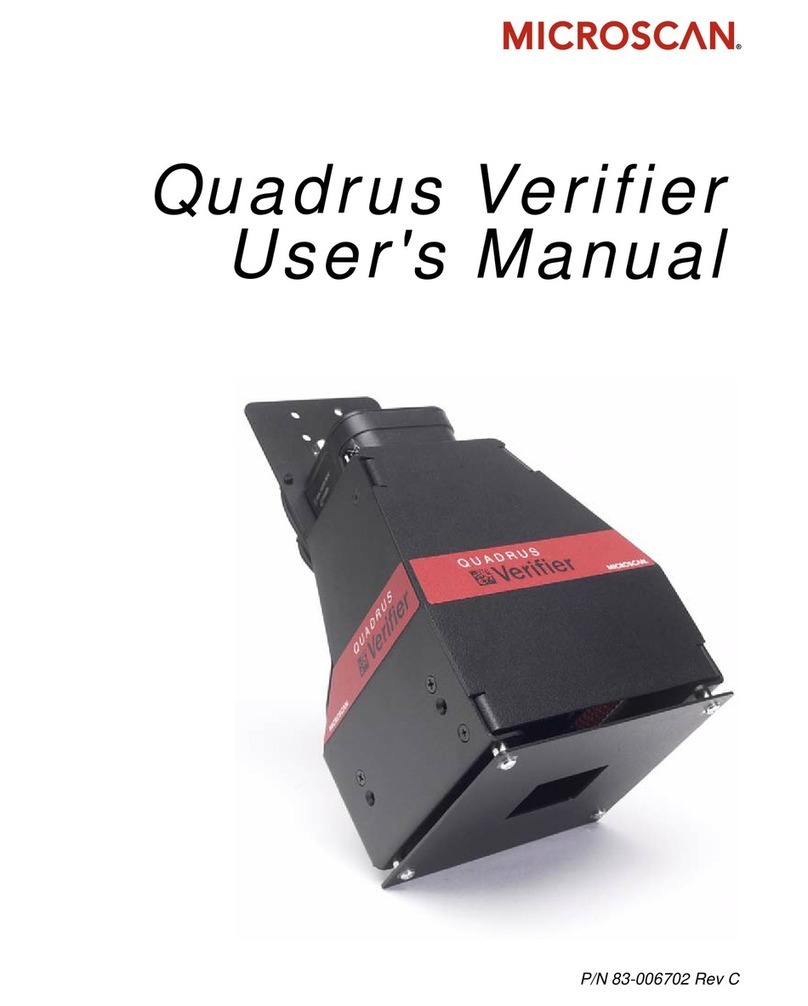
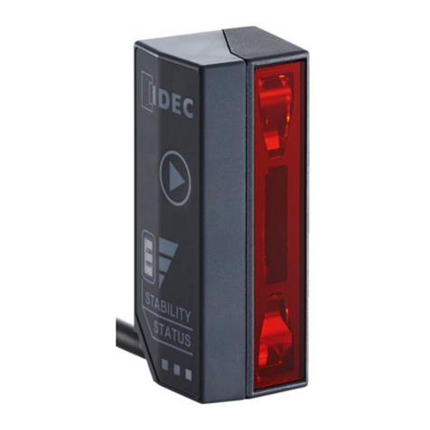
Opticon MDI-4 00/N210 Series User manual

2D Scan Engine
MDI-4x00 /N210Image Capture
This document describes image capture procedures
for the imager scan engines MDI-4x00 and N-210
Image Capture Manual
MDI-4x00 N-210

MDI-4x00 / N210 Image Capture
Image Capture Manual
All information subject to change without notice.
Document History
Model Number:
MDI-4x00/N210
Specification Number:
TBD
Edition:
First
Original Spec Number:
TBD
Date:
20 october 2022
Copyright 2022 Opticon. All rights reserved.
This manual may not, in whole or in part, be copied, photocopied, reproduced, translated or converted to any electronic or
machine readable form without prior written consent of Opticon.
Limited Warranty and Disclaimers
PLEASE READ THIS MANUAL CAREFULLY BEFORE INSTALLING OR
USING THE PRODUCT.
Serial Number
A serial number appears on all Opticon products. This official registration number is directly related to the device
purchased. Do not remove the serial number from your Opticon device. Removing the serial number voids the warranty.
Warranty
Unless otherwise agreed in a written contract, all Opticon products are warranted against defects in materials and
workmanship for two years after purchase. Opticon will repair or, at its option, replace products that are defective in
materials or workmanship with proper use during the warranty period. Opticon is not liable for damages caused by
modifications made by a customer. In such cases, standard repair charges will apply. If a product is returned under
warranty and no defect is found, standard repair charges will apply. Opticon assumes no liability for any direct, indirect,
consequential or incidental damages arising out of use or inability to use both the hardware and software, even if Opticon
has been informed about the possibility of such damages.
Packaging
The packing materials are recyclable. We recommend that you save all packing material to use should you need to
transport your scanner or send it for service. Damage caused by improper packaging during shipment is not covered by
the warranty.
Trademarks
Trademarks used are the property of their respective owners.
Opticon Inc. and Opticon Sensors Europe B.V. are wholly owned subsidiaries of OPTOELECTRONICS Co., Ltd., 12-17,
Tsukagoshi 4-chome, Warabi-shi, Saitama, Japan 335-0002. TEL +81-(0) 48-446-1183; FAX +81-(0) 48-446-1184
SUPPORT
USA
Europe
Phone: 800-636-0090
Email: [email protected]
Web: www.opticonusa.com
Web: www.opticon.com

MDI-4x00 / N210 Image Capture
Image Capture Manual
Revision History
Specification No. : TBD
Product name : MDI-4x00/N210
Edition
Date
Page
Section
Description of Changes
1st
2022/10/20
-
-
Initial release
2nd
2022/11/23
front
-
Added MDI-4100 picture and corrected product name
12
-
Removed reference to non exiting SDK

MDI-4x00 / N210 Image Capture
Image Capture Manual
Table of contents
Page
1. Abstract.....................................................................................................................................1
2. Configuration Commands........................................................................................................1
2.1. Configuring with Commands..............................................................................................1
2.1.1. Command Format......................................................................................................................1
2.1.2. Command Usage Precautions...................................................................................................1
3. Image Capture Mode ................................................................................................................2
3.1. Functional Overview..........................................................................................................2
3.1.1. Show Image Processing Settings..............................................................................................2
3.1.2. Change Image Processing Settings..........................................................................................3
3.1.3. Capture Image (DE8) ................................................................................................................6
3.2. Operation Flow..................................................................................................................9
3.3. Output Protocol ...............................................................................................................10
3.3.1. Image Information Format.......................................................................................................10
3.3.2. Calculation of the checksum....................................................................................................10
3.3.3. Output Image...........................................................................................................................12
3.4. Special Instruction...........................................................................................................12

MDI-4x00 / N210 Image Capture
Image Capture Manual
1
1. Abstract
This document describes image capture procedures for the imager scan engines MDI-4x00 and N-210.
2. Configuration Commands
2.1. Configuring with Commands
By sending the commands via the (USB) serial interface, you can configure the function settings for the
scan engine. These commands are also use to control and enter image capture mode. The default
command format is as shown below.
2.1.1. Command Format
The command format, from header to terminator, is defined as below, and the commands are
executed in packets.
Command Header *2
Command ID *1
Command Terminator *2
<ESC>
(1BH)
none
1 ~ 2 digits (ASCII)
<CR>
(ODH)
[(5BH)
3 digits (ASCII)
](5DH)
4 digits (ASCII)
*1 It is possible to send multiple command IDs between a single header and terminator, except for a single
command (1-digit) IDs.
*2 A combination of command header <STX>(02H) and terminator <ETX>(03H) is also possible.
Input examples:
1-digit command : <Esc>△<CR>
2-digit command : <Esc>△△<CR>
3-digit command : <Esc>[△△△<CR>
4-digit command : <Esc>]△△△△<CR>
2 and 3 digits command : <Esc>△△[△△△<CR>
2.1.2. Command Usage Precautions
When sending multiple commands in a sequence, the subsequent command is not received while the
previous command is still being executed. Since the RTS output will be in busy state while a
command is executed when the Handshake is set to BUSY/READY or MODEM, it is recommended to
refer to this signal for the right timing.
Any settings configured by commands are not retained in the non-volatile memory. Therefore, these
will be lost when the scan engine power is turned off. When the power comes back on, the scan
engine will be in the configuration state saved in the non-volatile memory. In order to save the settings
with commands, send “Z2” to save all the parameters in non-volatile memory.
Command packet maximum buffer size is 1000 characters.
If more characters than maximum limit are sent, lack of a part of command, etc. occurs and the
execution will not be performed correctly.

MDI-4x00 / N210 Image Capture
Image Capture Manual
2
3. Image Capture Mode
This chapter describes the details of the image capture mode.
The scan engine has an image capture mode in which it can process and transmit the image.
3.1. Functional Overview
The following commands can be used for image capture mode. The transmission of the image is
supported by serial (UART) and USB-COM interfaces only. Image processing settings contain settings
of raw image cropping, subsampling and bit depth change.
Command
Description
Remark
DE6
Show image processing settings
DE7
Change image processing settings
DE8
Capture image
3.1.1. Show Image Processing Settings
Use the “DE6” command to output the current image processing settings in the following format.
[Format]
1
T
r
i
m
(
2
,
3
,
4
,
5
)
S
u
b
(
6
,
7
)
B
p
8
J
q
9
F
f
10
T
r
11
rR
e
12
13
[Field]
No.
Field
Size
[byte]
Effective
range
Details
1
Start Character
1
0x3B
‘;’
2
Trimming Left
4
0 ~ 639
The top left and bottom right coordinates of the
image part that will be transmitted.
3
Trimming Top
4
0 ~ 479
4
Trimming Right
4
0 ~ 639
5
Trimming Bottom
4
0 ~ 479
6
Sub Sampling Horizontal
1
1, 2, 4
Set subsampling horizontal
7
Sub Sampling Vertical
1
1, 2, 4
Set subsampling vertical
8
Bit per Pixel
2
1, 4, 8, 10
Bits per pixel (depth)
9
Jpeg Quality
3
5 ~ 100
Quality of JPEG compression
10
File Format
4
1, 3
Output format 1: JPEG , 3: BMP
11
Transfer Type
4
Transmission mode
PART: Divided
ALL: Batch
12
Color Reverse
1
0, 1, 2
Reverse black and white
0: Non-inverted
1: Inverted
2: In status quo
13
End Character
1
0x0D
CR
[Output example]
;Trim( 0, 0, 639, 479) Sub(1,1) Bp 8 Jq 65 FfBMP TrPART Re2

MDI-4x00 / N210 Image Capture
Image Capture Manual
3
3.1.2. Change Image Processing Settings
Use “DE7” command to change the various settings of image processing. Input Q0 ~ Q9 commands
six times after the “DE7” command for various configurations.
Command
Description
Default
DE7
Qa
Qb
Qc
Qd
Qe
Qf
Set image processing
Q1
Q0
Qc
Qd
Qe
Qf
Set leftmost value for cropping
1000c + 100d + 10e + f = 0 ~ 751
0
Q1
Q1
Qc
Qd
Qe
Qf
Set top edge value for cropping
1000c + 100d + 10e + f = 0 ~ 479
0
Q1
Q2
Qc
Qd
Qe
Qf
Set rightmost value for cropping
1000c + 100d + 10e + f = 0 ~ 751
639
Q1
Q3
Qc
Qd
Qe
Qf
Set bottom edge value for cropping
1000c + 100d + 10e + f = 0 ~ 479
479
Q2
Q0
Q0
Q0
Q0
Qf
Set horizontal subsampling
f = 1, 2, 4
1
Q2
Q1
Q0
Q0
Q0
Qf
Set vertical subsampling
f = 1, 2, 4
1
Q3
Q0
Q0
Q0
Q0
Qf
Set bit depth (bits per pixel)
f = 0: 8 bits (256 values)
f = 1: 4 bits (16 values)
f = 2: 1 bits (2 values)
f = 3: 10 bits (1024 values, raw data)
0
Q4
Q0
Q0
Qd
Qe
Qf
Set JPEG quality
100d + 10e + f = 5 ~ 100
75
Q5
Q0
Q0
Q0
Q0
Qf
Output format
f = 1: JPEG
f = 3: BMP
3
Q6
Q0
Q0
Q0
Q0
Qf
Transmission mode
f = 0: PART
f = 1: ALL
0
Q8
Q0
Q0
Q0
Q0
Qf
Reverse black and white
f = 0: Non-inverted
f = 1: Inverted
f = 2: In status quo
2
Example of command transmission 1: Set coordinate (left 100, top 100, right 500, bottom 300) for
image cropping.
<ESC>[DE7Q1Q0Q0Q1Q0Q0[DE7Q1Q1Q0Q1Q0Q0[DE7Q1Q2Q0Q5Q0Q0[DE7Q1Q3Q0Q3Q0Q0
<CR>
Example of command transmission 2: Set horizontal subsampling 1/2, vertical subsampling 1/4.
<ESC>[DE7Q2Q0Q0Q0Q0Q2[DE7Q2Q1Q0Q0Q0Q4<CR>
Example of command transmission 3: Set transmission mode to All and bit depth to 4 bits.
<ESC>[DE7Q6Q0Q0Q0Q0Q1[DE7Q3Q0Q0Q0Q0Q1<CR>

MDI-4x00 / N210 Image Capture
Image Capture Manual
4
■Cropping
The removal of the outer parts of the original image (light-blue area) in order to retrieve only the
necessary part (yellow area).
(0,0)
(751, 479)
(Ltrim, Ttrim)
(Rtrim, Btrim)
■Subsampling
Thinning out pixel data in row and column directions to compress the data size.
In the setting of horizontal 2, the data is thinned out by removing one column from each two columns
as shown in the figure below. The amount of information per line (in the horizontal direction) will then
be 1/2.
In the setting of vertical 4, the data is thinned out by removing three rows from each four rows as
shown in the figure below. The amount of information per line (in the vertical direction) will then be 1/4.

MDI-4x00 / N210 Image Capture
Image Capture Manual
5
■Bit depth
Bit depth (bits per pixel) can be configured. When bit depth is set, the amount of information
decreases, but the color gradation that can be displayed also decreases.
When the amount of information of 10 bits (raw data) is 1, that of 8 bits, 4 bits and 1bit are 1/2, 1/4
and 1/16 respectively.
Bit depth Raw data: 16 bits (2 bytes) per pixel, use upper 10 bits of 2 bytes
10 bit
8 bit Extract upper 8 bits from 16 bits, 8 bits per pixel (1 byte per pixel)
4bit Extract upper 4 bits, 4 bits per pixel (1 byte per 2 pixels)
1bit Extract upper 1 bit only, 1 bit per pixel (1 byte per 8 pixels)
■JPEG quality
Quality of JPEG conversion is configured. When lower quality is set, the amount of information
decreases, but the image quality also decreases.
■Output format
Output format of JPEG or BMP (bitmap). When JPEG is configured, lossy compression is used and
the image is transmitted in standard JPEG format. In BMP mode, only the data (uncompressed color
saturation values) is transmitted; the bitmap header is omitted.

MDI-4x00 / N210 Image Capture
Image Capture Manual
6
3.1.3. Capture Image (DE8)
With the “DE8”command, the scan engine can go to Image Capture mode to take an image.
After capturing an image or the timeout expiration without capturing, Image Capture mode turns off
and the scan engine then returns to normal operation.
When the scan engine receives this command, it starts to wait for a trigger. The next trigger then
initiates the image capture (no decoding). Immediately after the image is captured, image data is
output as described later in “Output protocol”.
There are two additional parameters, ‘selecting capture mode’and ‘timeout setting’, and those are
send in the following formats. Each parameter is specified with “Q0”~ ”Q9”and the data lengths are
fixed. Timeout setting may not be required depending on the configured Capture mode.
Command
Description
Effective value
DE8
Qa
Qb
Qc
Qd
Enter image capture mode
m
Select capture mode
m = a
0, 1, 2, 3
n
Set timeout [seconds]
n = 100b + 10c + d
0 ~ 999
Example of command transmission: Commands in conjunction mode
<ESC>[DE8Q0<CR>
Example of command transmission: Trigger Capture (2) timeout 15 seconds
<ESC>[DE8Q2Q0Q1Q5<CR>
[m: Select capture mode]
m
Capture mode
Description
Remark
0
Commands in
conjunction
Capture image immediately after receiving
command.
n (timeout setting is
not needed)
1
Trigger capture (1)
Emit aiming immediately after receiving
command. Capture image when the trigger
is pressed.
2
Trigger capture (2)
Wait for trigger press after receiving
command. Emit aiming as long as the trigger
is kept pressed. Capture image when the
trigger is released.
3
Trigger capture (3)
Wait for trigger after receiving command.
Emit aiming LED after 1st trigger. Capture
image after 2nd trigger.

MDI-4x00 / N210 Image Capture
Image Capture Manual
7
Timing chart for each capture mode are described below.
All signals in the following figures are Active Low, and Capture includes Output.
m=0 : Commands in conjunction mode
Image Capture
Aiming
Trigger
Image Capture
Mode
m=1 : Trigger Capture (1)
Image Capture
Aiming
Trigger
Image Capture
Mode
m=2 : Trigger Capture (2)
Image Capture
Aiming
Trigger
Image Capture
Mode
m=3 : Trigger Capture (3)
Image Capture
Aiming
Trigger
Image Capture
Mode

MDI-4x00 / N210 Image Capture
Image Capture Manual
8
[n: Timeout setting]
Timeout of ‘Image Capture mode’can be set in units of seconds. The effective values are 0 (000) ~
999. For ‘Commands in Conjunction mode (m = 0)’, the timeout value is ignored. The timeout period is
measured from command reception to capturing. When n=0, there is no timeout and the scan engine
will wait indefinitely for a trigger input. When n > 0, this value specifies the timeout period in seconds.
n
Timeout period
Remark
0
None
Wait indefinitely for a trigger
1 –999
Specified periods [second]
When there is no trigger input during timeout period ‘t’, image capture mode is turned off after the ‘t’
expires. Normal decoding will then be performed by subsequent trigger inputs.
In Trigger Capture (2) mode, the trigger needs to be released during the period of ‘t’to take a picture.
If it is not released, the aiming stops after ‘t’expires and Image Capture mode is turned off. If the
trigger is released, no operation is performed.
Image Capture
Aiming
Trigger
Image Capture
Mode t
In Trigger Capture (3) mode, the trigger needs to be pressed twice during the period of ‘t’to take a
picture. Aiming will turn on after the first trigger and it will be turned off after ‘t’expires. Normal
decoding will be performed with the second trigger in that case.
Image Capture
Aiming
Trigger
Image Capture
Mode t

MDI-4x00 / N210 Image Capture
Image Capture Manual
9
3.2. Operation Flow
The following figure shows the flow of image capture operation.
Trigger
pressed
in time?
Send “DE8”
command
Yes
No End image
capture mode
Enter image
capture mode
Capture image
Transmission
Send
ImageInformation
[Information]
PART
Send
ImageInformation
[Information]
+
[Data]
ALL
Receive
response
Resend
NAK
ACK
Receive
response
Resend
NAK
Resend
NAK
ENQ
Retry
transmission Repeat till
last line
Send
ImageInformation
[Data] line by line
Receive
response
ACK
Transmission
complete
ETB: Transmission
complete
CAN: Stop
transmission
ETB: Transmission
complete
CAN: Stop
transmission

MDI-4x00 / N210 Image Capture
Image Capture Manual
10
3.3. Output Protocol
Protocol used for output is described below.
3.3.1. Image Information Format
[Function]
This is used for image output. The image information (Information) and the image itself (Data) may be
contained in the image output.
[Format]
Start Char
rec No
Length
(A)
Information, Data (*)
Check Sum
End Char
0x21
0x0D
* When Transmission mode is ALL, Information is transmitted, followed by Data (entire image).
[Field]
Field
Size
[byte]
Details
Start Character
1
‘!’ (0x21)
rec No
2
Default value is 0.
When packets in the same format are sent continuously, this field is
incremented sequentially.
Length
4
The size of (A)
(A)
*
Information
Information of image
Data
Image itself
PART transmission mode: send line by line
ALL transmission mode: send an entire image
Check Sum
2
Calculated according to the method described below.
End Character
1
<CR> (0x0D)
* Refer to next page for each format.
3.3.2. Calculation of the checksum
Description
The checksum is the 16 bit sum of the data elements with index i (0,1,2,….) weighted by (i+1).
Calculation method
Start with a checksum of 0; then, for each data element with index 0, 1, 2, 3, and so on, multiply the
value of the data element by its index+1, and add the result to the checksum, keeping only the 16
least significant bits.
As a formula
Checksum=( ∑
i=0
length−1xi∗(i+1))mod216

MDI-4x00 / N210 Image Capture
Image Capture Manual
11
a) Details of Information Field
The Information field comprises the following subfields.
[Subfield]
No.
Subfield
Size
[byte]
Effective range
Details
1
Identifier
1
00h ~ FFh
Shows field version
2
Image Size
4
Size of output image
3
Image Number
2
0 ~ 9
Image identification number in memory
4
Image Width
2
1 ~ 640
Width of processed image [pixel]
5
Image Height
2
1 ~ 480
Height of processed image [pixel]
6
Trimmed Left
2
0 ~ 639
Leftmost value of processed image
7
Trimmed Top
2
0 ~ 479
Top edge value of processed image
8
Trimmed Right
2
0 ~ 639
Rightmost value of processed image
9
Trimmed Bottom
2
0 ~ 479
Bottom edge value of processed image
10
Sub sampling Horizontal (SW)
1
1, 2, 4
Subsampling value in horizontal direction for
output
11
Sub sampling Vertical (SW)
1
1, 2, 4
Subsampling value in vertical direction for output
12
Maximum Brightness
2
0 ~ 1023
Maximal brightness of processed image (1024-
level)
13
Bit per Pixel (BPP)
1
1, 4, 8, 10
Bit depth per pixel
14
File format
1
1, 3
File format 1: JPEG, 3: BMP
15
Shot Left
2
0 ~ 751
Leftmost coordinate of raw image
16
Shot Top
2
0 ~ 479
Top edge coordinate of raw image
17
Shot Right
2
0 ~ 751
Rightmost coordinate of raw image
18
Shot Bottom
2
0 ~ 479
Bottom edge coordinate of raw image
19
Binning Horizontal (HW)
1
1
Subsampling value in horizontal direction for
capture
20
Binning Vertical (HW)
1
1
Subsampling value in vertical direction for
capture
21
Amplification
2
0 ~ 1500
Gain
22
Exposure Time
4
50 ~ 500000
Exposure time
23
Brightness Index Value
2
0 ~ 1023
Brightness index value (1024-level)
24
Total Transfer Count
2
0 ~ 65535
Number of image information transmissions,
including this packet
25
Reserved
211 (*)
0
(For expansion)
* The total size used excluding Reserved is subtracted from 256.
b) Details of Data Field
The Data field comprises the following subfield.
[Subfield]
No.
Subfield
Size
[byte]
Effective
range
Details
1
Image Data
*
*
Output image data
[Part transmission] line by line (horizontal width)
[All transmission] entire image
* Those vary depending on the file format type and BPP setting. In the case of JPEG format, the horizontal width
of the original image is transmitted (which is different from the real line information because of compression).

MDI-4x00 / N210 Image Capture
Image Capture Manual
12
3.3.3. Output Image
The Image Information format is used for the image output. The way to output an image varies
depending on the transmission modes. The output images in each transmission mode are as shown
below.
1. PART transmission
The image information (information) is sent in the first packet, followed by the image itself (Data).
Packet 0
Start Char
rec No = 0
Length = 256
Information
Check Sum
End Char
Packet 1
Start Char
rec No = 1
Length
Data
Check Sum
End Char
.
.
.
Packet n
Start Char
rec No = n
Length
Data
Check Sum
End Char
2. ALL transmission
The image information (information) and the image itself (Data) are all send in the first packet.
Packet 0
Start Char
rec No = 0
Length
Information
Data
Check Sum
End Char
3.4. Special Instruction
・Bar codes and 2D codes cannot be read during image capture mode.
・An image which was used for reading a bar code or 2D code is not output.
Table of contents
Other Opticon Scanner Accessories manuals