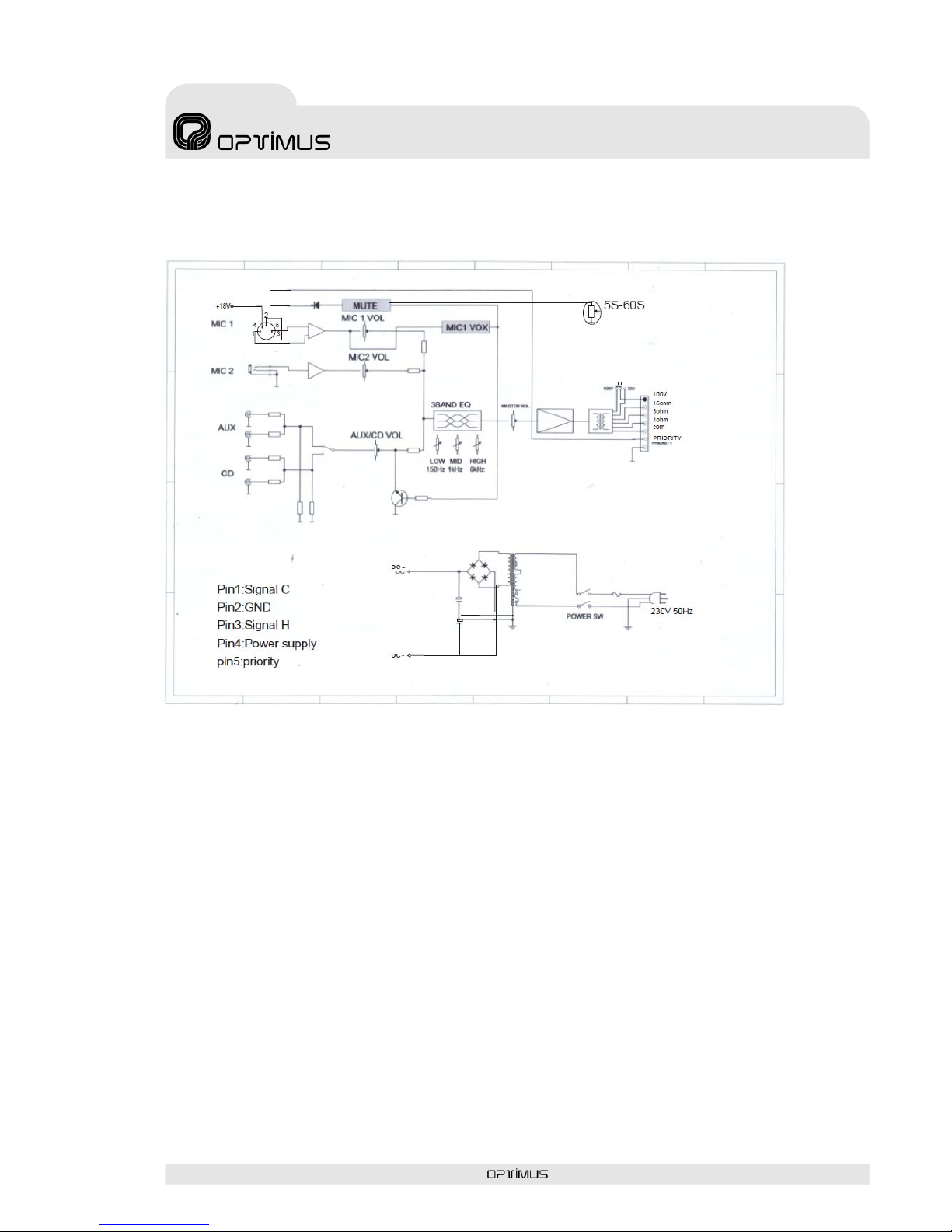
Optimus Am-120 User manual

AMPLIFICADOR
AMPLIFIER
AM-120
Manual de instalación y funcionamiento v1.0
Installation and operating instructions v1.0

AM-120 Versión 1.0 Página 1 de 8
A
M-120 Amplificador
INSTRUCCIONES DE SEGURIDAD:
IMPORTANTE:
Los códigos de color de los cables de red son los siguientes:
Si los colores de los cables de red de este aparato no se corresponden con las marcas de sus
terminales de conexión, debe procederse como sigue:
Conectar el cable de color verde y amarillo al terminal marcado con la letra E o con el símbolo
de tierra. Conectar el cable de color azul al terminal negro o marcado con la letra N. Conectar el
cable de color marrón al terminal rojo o marcado con la letra L.
INSTALACIÓN GENERAL
NO PASAR los cables de micrófono cerca de cables telefónicos, de datos o de línea de 100 V.
NO PASAR los cables de línea de 100 V cerca telefónicos, de datos o de baja tensión.
NO SOBREPASAR el 90% de la potencia de salida de los amplificadores cuando se utiliza la
línea de 100 V para avisos.
NO SOBREPASAR el 70% de la potencia de salida de los amplificadores cuando se utiliza la
línea de 100 V para música ambiental a alto volumen.
NO UTILIZAR altavoces exponenciales para música ambiental, excepto si éstos han sido
especialmente diseñados para esta función.
EVITAR empalmes en los cables de micrófono. Si es inevitable, utilizar exclusivamente conectores
blindados de buena calidad, como los XLR.
Utilizar SIEMPRE para distancias largas, micrófonos balanceados de baja impedancia o aislados
de la masa conectados a entradas balanceadas.
Utilizar SIEMPRE un cable doble aislante de calidad equivalente a los de la red de baja tensión
para las conexiones de los altavoces.
ASEGURARSE de que todos los altavoces estén en fase.
ASEGURARSE de que no existe ningún cortocircuito en la línea de altavoces antes de conectarla
al amplificador.
Verde y amarillo Tierra (E)
Azul Neutro (N)
Marrón Positivo (L)

AM-120 Versión 1.0 Página 2 de 8
A
M-120 Amplificador
ÍNDICE
1. PANEL FRONTAL.....................................................................................................................3
2. PANEL POSTERIOR.................................................................................................................3
3. DIAGRAMA DE BLOQUES ......................................................................................................4
4. CONEXIONES...........................................................................................................................5
4.1. Conexión a la red eléctrica....................................................................................................5
4.2. Entradas de audio ..................................................................................................................5
4.2.1. MIC 1 .................................................................................................................................5
4.2.2. MIC 2 .................................................................................................................................5
4.2.3. Entrada AUX / CD.............................................................................................................5
4.3. Terminales de prioridad manual ...........................................................................................6
4.4. Conexión de los altavoces ....................................................................................................6
4.4.1. Línea de 100 V ..................................................................................................................6
4.4.2. Línea de 70 V (Seleccionable desde PCB).....................................................................6
4.4.3. Baja impedancia (4 Ω, 8 Ω, 16 Ω)....................................................................................6
5. ESPECIFICACIONES TÉCNICAS ............................................................................................7
6. CERTIFICADO DE GARANTÍA ................................................................................................8

AM-120 Versión 1.0 Página 3 de 8
A
M-120 Amplificador
1. PANEL FRONTAL
2. PANEL POSTERIOR
4. Control de ecualización
5. Control de volumen MASTER
6. Interruptor de alimentación
7. Led de alimentación
1. Control de volumen MIC 1
2. Control de volumen MIC 2
3. Control de volumen AUX / CD
1. Conector alimentación CA
2. Portafusibles
3. Tornillo de conexión a masa
4. Terminales de prioridad manual
5. Terminales de salida a altavoces
6. Entrada auxiliar (2 x RCA)
7. Entrada de CD (2 x RCA)
8. Interruptor de selección AUX / CD
9. Entrada MIC 2 (Jack Mono 1/4”)
10. Entrada MIC 1 (DIN / Balanceado)

AM-120 Versión 1.0 Página 4 de 8
A
M-120 Amplificador
3. DIAGRAMA DE BLOQUES

AM-120 Versión 1.0 Página 5 de 8
A
M-120 Amplificador
4. CONEXIONES
4.1. Conexión a la red eléctrica
El transformador suministrado está diseñado para usar una toma de 230 V de corriente alterna.
4.2. Entradas de audio
4.2.1. MIC 1
Conector DIN estándar para señal de micro balanceada situado en la parte posterior del equipo. El
cableado se expone a continuación:
Pin1: Señal (+)
Pin2: GND
Pin3: Señal (-)
Pin4: +18 Vcc
Pin5: Priority
Gire el control frontal correspondiente en el sentido horario u antihorario para aumentar o disminuir
respectivamente el volumen de esta entrada.
4.2.2. MIC 2
Conector jack mono de 1/4" para señal de micro no balanceada situado en la parte posterior del
equipo. El cableado se expone a continuación:
Cuerpo: GND
Punta: Señal
Gire el control frontal correspondiente en el sentido horario u antihorario para aumentar o disminuir
respectivamente el volumen de esta entrada.
4.2.3. Entrada AUX / CD
Este equipo está provisto de una entrada auxiliar la cual puede ser usada para conectar fuentes
de sonido tales como sintonizadores de radio, reproductores de CD, casete…
Los conectores son de tipo RCA estándar y están enlazados internamente, permitiendo así el uso
de señales estéreo sin necesidad de utilizar un cable especial, de todos modos se recomienda
consultar con el fabricante de la fuente de sonido para asegurar que no se producirá ningún daño
en la misma si sus canales de salida son unidos en paralelo.
Cuerpo: GND
Punta: Señal

AM-120 Versión 1.0 Página 6 de 8
A
M-120 Amplificador
Gire el control frontal correspondiente en el sentido horario u antihorario para aumentar o disminuir
respectivamente el volumen de esta entrada.
4.3. Terminales de prioridad manual
El cierre de este contacto silenciará las entradas MIC 2 y AUX/CD.
4.4. Conexión de los altavoces
Este equipo está provisto de diferentes salidas de línea de altavoces tales como 100 V, 70 V y
baja impedancia. Solo es posible usar una de estas salidas a la vez, la conexión a más de una
salida simultáneamente puede resultar en daños internos al amplificador.
4.4.1. Línea de 100 V
Este tipo de altavoces son más comúnmente usados en Europa para instalaciones de megafonía.
Cuando el amplificador trabaje en su nivel de salida nominal, estos terminales de salida
proporcionaran una tensión de 100 V RMS. Use únicamente altavoces para línea de 100 V en esta
salida. Todos los altavoces se deben cablear en paralelo y la suma de potencias de los mismos no
debe exceder la potencia de salida del amplificador. Es recomendable, en el caso de usar fuentes
musicales, no cargar el amplificador a más de un 70% de su potencia máxima.
4.4.2. Línea de 70 V (Seleccionable desde PCB)
Este sistema es común en EEUU, trabaja exactamente con los mismos principios que la línea de
100 V excepto que la tensión nominal en los terminales de salida es de 70 V RMS.
4.4.3. Baja impedancia (4 Ω, 8 Ω, 16 Ω)
Esta salida permite la conexión de altavoces estándar de baja impedancia. La impedancia de
carga mínima es 4 Ω. Cuando se conecte más de un altavoz, asegúrese que estén cableados de
tal forma que la impedancia total tenga un valor entre 4 Ωy 16 Ω.

AM-120 Versión 1.0 Página 7 de 8
A
M-120 Amplificador
5. ESPECIFICACIONES TÉCNICAS
Modelo AM-120
Potencia de salida (RMS) 120 W
Alimentación 230 Vca 50 Hz
THD a potencia máxima < 2% 1 kHz
Salidas de altavoces 4 Ω, 8 Ω, 16 Ω, 70 V y 100 V
Respuesta en frecuencia 100 Hz ~ 20 kHz (± 3 dB)
Entrada de micrófono prioridad 1.2 mV, 600 ΩBalanceado
Entrada de micrófono 2 1,8 mV, 600 Ω
Entrada auxiliar 300 mV, 50 kΩ
Entrada de CD 1.1 V 50 kΩ
SNR entradas micrófono > 60 dB
SNR entradas AUX/CD > 70 dB
Ecualizador 150Hz, 1KHz, 6KHz ± 10 dB
Dimensiones (alto x ancho x fondo) 90 x 430 x 270 mm
Peso 10,5 kg

AM-120 Versión 1.0 Página 8 de 8
A
M-120 Amplificador
6. CERTIFICADO DE GARANTÍA
1. La empresa OPTIMUS S.A. garantiza que sus productos se encuentran libres
de defectos en materiales y de mano de obra en el momento de su entrega
original al comprador.
2. La empresa OPTIMUS S.A. concede a sus productos, conforme a las
condiciones aquí descritas, una garantía de dos (2) años a partir de la fecha de
adquisición del producto por el comprador. Si, dentro de este plazo de garantía,
se producen defectos que no sean debidos a razones mencionadas bajo el punto
2, la empresa OPTIMUS S.A. remplazará o reparará el aparato utilizando piezas
de recambio equivalentes, nuevas o reconstruidas, según criterio propio. Si se
aplican piezas de recambio que constituyen una mejora del aparato, la empresa
OPTIMUS S.A. se reserva el derecho de cargar el coste adicional de estos
componentes al cliente.
3. No se concederán prestaciones de garantía distintas a las citadas.
4. Para la utilización de los derechos de garantía será requisito indispensable
presentar la factura de compra original o el certificado de garantía.
2. DISPOSICIONES DE GARANTÍA
1. Si el producto tuviera que ser modificado o adaptado para cumplir con los
requisitos locales en cuanto a técnica o seguridad, si no se trata del país para el
cual el producto fue concebido y fabricado originalmente, ello no se considera
como defecto de material o de fabricación. Por lo demás, la garantía no
comprende la realización de estas modificaciones o adaptaciones,
independientemente de si éstas hayan sido ejecutadas debidamente o no.
OPTIMUS S.A. tampoco asumirá costes en el marco de la garantía por este tipo
de modificaciones.
2. La garantía no dará derecho a inspección o mantenimiento gratuito o
reparación del aparato, particularmente si los defectos son debidos a uso
inapropiado. Los derechos de garantía tampoco abarcan defectos en piezas de
desgaste que sean debidos a un desgaste normal. Piezas de desgaste son, en
particular, potenciómetros, interruptores/teclas, y piezas similares.
3. La garantía no abarca los defectos en el equipo causados por:
¾Abuso o uso incorrecto del aparato para fines distintos a los previstos, en
incumplimiento de las instrucciones de servicio y de mantenimiento
especificadas en el Manual y/o Instrucciones Técnicas del equipo.
¾Conexión o uso del producto de una manera que no corresponda a los
requisitos técnicos o de seguridad del país en el cual se utiliza el aparato.
¾Instalación en condiciones distintas a los indicados en el Manual y/o
Instrucciones Técnicas.
¾Deficiencia o interrupciones tensión eléctrica o defectos de instalación que
impliquen uso en condiciones anormales.
¾Daños ocasionados por otros equipos interconectados al producto.
¾El uso o instalación de Software (programas), interfaces, partes o
suministros no proporcionados y/o autorizados por OPTIMUS S.A.
¾La no utilización de los embalajes originales para su transporte.
¾Daños causados por fuerza mayor u otras causas no imputables a
OPTIMUS S.A.
4. No están cubiertos por esta garantía los siguientes elementos:
¾Todas las superficies de plástico y todas las piezas expuestas al exterior
que hayan sido rayadas o dañadas debido al uso normal o anormal.
¾Las roturas, golpes, daños por caídas o ralladuras causadas por traslados
de cualquier naturaleza.
¾Defectos de daños derivados de pruebas, uso, mantenimiento, instalación
y ajustes inapropiados, o derivados de cualquier alteración o modificación
de cualquier tipo no realizada por en Servicio Autorizado por OPTIMUS
S.A. en cumplimiento de esta garantía.
¾Los daños personales o a la propiedad que pudieran causar el uso
indebido del equipo, incluyendo la falta de mantenimiento.
5. La garantía carecerá de validez cuando se observe:
¾Enmiendas o tachaduras en los datos del certificado de garantía o factura
de compra.
¾Falta de factura original o falta de fecha en la misma.
¾Falta de número de serie o lote en el equipo.
6. La garantía no cubre los desplazamientos por asistencias técnicas a excepción
de los motivados por incidencias ocurridas durante los tres primeros meses.
7. En el caso de ordenadores PC, la garantía no cubrirá la eliminación de virus
informáticos, restauración de programas por este motivo o la reinstalación del
disco provocada por el borrado del mismo.
8. Los derechos de garantía se anulan si el producto ha sido reparado o abierto
por un personal no autorizado OPTIMUS S.A. o por el propio cliente.
9. Si la empresa OPTIMUS S.A. estableciera al comprador del aparato que los
daños presentados no dan derecho a la reclamación de la garantía, los costes de
las prestaciones de revisión por parte de la empresa OPTIMUS S.A. correrán a
cargo del cliente.
10. Los productos sin derechos de garantía sólo se repararán contra pago de los
gastos por el cliente. En caso de ausencia de derechos de garantía, OPTIMUS
S.A. informará al cliente al respecto. Si, en un plazo de 6 semanas a partir de
esta comunicación, no recibimos ninguna orden de reparación escrita
confirmando la aceptación de los gastos, OPTIMUS S.A. devolverá el aparato en
cuestión al cliente. En este caso, los gastos de transporte y embalaje se
facturarán por separado y se cobrarán contra reembolso. En caso de expedición
de una orden de reparación, confirmando la asunción de los gastos, los gastos
de transporte y de embalaje se facturarán adicionalmente, igualmente por
separado.
11. En caso de necesidad de traslado al Centro de Servicio Autorizado, el
transporte será realizado por el responsable de la garantía, y serán a su cargo
los gastos de flete y seguro.
12. En caso de falla, OPTIMUS S.A. asegura al comprador la reparación y/o
reposición de partes para su correcto funcionamiento en un plazo no mayor a 30
días. No obstante, se deja aclarado que el plazo usual no supera los 30 días.
13. Todas las piezas o productos sustituidos al amparo de los servicios en
garantía pasarán a ser propiedad de OPTIMUS S.A.
3. TRANSFERENCIA DE LA GARANTÍA
La garantía se concede únicamente para el comprador original (cliente principal)
y es intransferible. Con excepción de la empresa OPTIMUS S.A., ningún tercero
(comerciantes, etc.) está autorizado a conceder garantía adicionales en nombre
de la empresa OPTIMUS S.A.
4. RECLAMACIONES POR DAÑOS Y PERJUICIOS
En caso de que OPTIMUS S.A. no pueda proporcionar un servicio de garantía
adecuado, el comprador no tendrá ningún derecho a reclamar indemnización
alguna por daños y perjuicios consecuentes. La responsabilidad de la empresa
OPTIMUS S.A. se limita en todo caso al precio de facturación del producto
5. RELACIÓN CON OTROS DERECHOS DE GARANTÍA Y CON EL DERECHO
NACIONAL
1. Mediante esta garantía no se afecta a los derechos del comprador frente al
vendedor deducidos del contrato de compraventa concluido.
2. Las presentes condiciones de garantía de la empresa OPTIMUS S.A. son
válidas siempre que no contradigan el derecho nacional correspondiente en
relación con las disposiciones de garantía.
3. OPTIMUS S.A. asegura que este producto cumple con las normas de
seguridad vigentes en el país.
ESTA DECLARACIÓN DE GARANTÍA LIMITADA ES LA GARANTÍA
EXCLUSIVA OFRECIDA POR OPTIMUS S.A. SE EXCLUYE TODA OTRA
GARANTÍA EXPLÍCITA O IMPLÍCITA, INCLUIDAS LAS GARANTÍAS DE
COMERCIALIDAD Y APTITUD A UN FIN DETERMINADO. (EXCEPTO
CUANDO DICHAS GARANTÍAS SEAN REQUERIDAS POR UNA LEY
APLICABLE). NINGUNA GARANTÍA, YA SEA EXPLÍCITA O IMPLÍCITA, SE
APLICARÁ TRAS LA FINALIZACIÓN DEL PERIODO DE GARANTÍA.
OPTIMUS S.A.
Servicio Post Venta
C/ Barcelona 101
17003 - GIRONA
Tel. 902 151 96 / 972 203 300
Fax. 972 21 84 13

AM-120 Version 1.0 Page 1of 8
A
M-120 Amplifier
SAFETY INSTRUCTIONS:
IMPORTANT:
The wires in the mains lead are coloured in accordance with the following code:
If the colours of the wires in the mains lead of this apparatus do not correspond with the colour
markings identifying the terminals in your plug, proceed as follows:
The wire which is coloured green and yellow must be connected to the terminal which is marked
by the letter E, or by the safety earth symbol or coloured green and yellow. The wire which is
coloured blue must be connected to the terminal which is marked with the letter N or coloured
black. The wire which is coloured brown must be connected to the terminal which is marked with
the letter L or coloured red.
GENERAL INSTALLATION
DO NOT run microphone cables near mains, data, telephone or 100V line cables.
DO NOT run 100V line cables near data, telephone or other low voltage cables.
DO NOT exceed 90% of the amplifier’s output power when using 100V line (speech only).
DO NOT exceed 70% of the amplifier’s output power when using 100V line (high level background
music).
DO NOT use horn loudspeakers for background music unless the loudspeaker has been
specifically designed for this purpose.
AVOID jointing the microphone cable, when this is unavoidable make sure a good screened
connector is used, e.g. XLR.
ALWAYS use a balanced or floating low impedance microphone terminating into a balanced input
on long microphone cable runs.
ALWAYS use a mains grade double insulated cable for the loudspeaker cable runs.
ENSURE that all loudspeakers are in-phase.
ENSURE that there are no short circuits on the loudspeaker line before connecting to the amplifier.
Green and Yellow Earth (E)
Blue Neutral (N)
Brown Live (L)

AM-120 Version 1.0 Page 2of 8
A
M-120 Amplifier
INDEX
1. FRONT PANEL.............................................................................................................3
2. REAR PANEL...............................................................................................................3
3. BLOCK DIAGRAM........................................................................................................4
4. CONNECTIONS............................................................................................................5
4.1. AC mains connection .......................................................................................................... 5
4.2. Audio inputs ......................................................................................................................... 5
4.2.1. MIC 1 ............................................................................................................................................. 5
4.2.2. MIC 2 ............................................................................................................................................. 5
4.2.3. AUX / CD input ........................................................................................................................... 5
4.3. Manual priority contact........................................................................................................ 6
4.4. Loudspeakers connection................................................................................................... 6
4.4.1. 100 V line ..................................................................................................................................... 6
4.4.2. 70 V line (inner PCB selectable) ............................................................................................ 6
4.4.3. Low impedance (4 Ω, 8 Ω16 Ω)............................................................................................. 6
5. TECHNICAL SPECIFICATIONS.....................................................................................7
6. GUARANTEE CERTIFICATE.........................................................................................8

AM-120 Version 1.0 Page 3of 8
A
M-120 Amplifier
1. FRONT PANEL
2. REAR PANEL
1. MIC 1 volume control
2. MIC 2 volume control
3. AUX / CD volume control
4. Equalization control
5. MASTER volume control
6. Power switch
7. Power indicator
1. AC Power plug
2. AC fuse holder
3. Ground connection screw
4. Manual priority contacts
5. Loudspeakers output connectors
6. Aux input (2 x RCA)
7. CD input (2 x RCA)
8. Selector switch AUX / CD
9. MIC 2 input (Jack Mono 1/4”)
10. MIC 1 input (DIN / Balanced)

AM-120 Version 1.0 Page 4of 8
A
M-120 Amplifier
3. BLOCK DIAGRAM

AM-120 Version 1.0 Page 5of 8
A
M-120 Amplifier
4. CONNECTIONS
4.1. AC mains connection
Supplied transformer has been designed to be used at 230 Vac
4.2. Audio inputs
4.2.1. MIC 1
Standard DIN connector for balanced mic signal placed at amplifier rear panel. Its pin out is as
follow:
Pin1: Signal (+)
Pin2: GND
Pin3: Signal (-)
Pin4: +18 Vcc
Pin5: Priority
Turn the correspondent front control knob clockwise or counter-clockwise to increase or decrease
the volume of this input.
4.2.2. MIC 2
1/4" Jack mono connector for unbalanced mic signal placed at amplifier rear panel. Its pin out is as
follow:
Slave: GND
Tip: Signal
Turn the correspondent front control knob clockwise or counter-clockwise to increase or decrease
the volume of this input.
4.2.3. AUX / CD input
This equipment has an aux input that can be used to connect audio sources such as tuners, CD
players, cassette players…
Connectors are standard RCA internally linked, making possible the use of stereo signal without
any special cable, anyway it’s recommended to ask audio source manufacturer to ensure that the
equipment won’t be damaged if the output channels are connected in parallel.
Ring: GND
Tip: Signal

AM-120 Version 1.0 Page 6of 8
A
M-120 Amplifier
Turn the correspondent front control knob clockwise or counter-clockwise to increase or decrease
the volume of this input.
4.3. Manual priority contact
Closing this contact, inputs MIC2 and AUX/CD will be muted.
4.4. Loudspeakers connection
This equipment has different loudspeakers outputs such as 100 V, 70 V and low impedance. It’s
only possible to use one output at the same time, connecting more than one may damage internal
parts of the amplifier.
4.4.1. 100 V line
These loudspeakers are most commonly used in Europe for PA distribution. When the amplifier is
at full output 100 V RMS will be present at the output terminals. Only use 100 V line loudspeakers
with this output. All loudspeakers are wired in parallel and the sum of their power must not exceed
the rated output power of the amplifier. It is advisable not to load the amplifier at more than 70% of
its rated output power when using music sources.
4.4.2. 70 V line (inner PCB selectable)
This system is common in the USA, it operates on the same principles as 100 V line except that at
rated output power amplifier has 70 V RMS on its output terminals.
The switch from 100 to 70 V has to be carried out inside the amplifier by changing the connection
of output transformer taps.
4.4.3. Low impedance (4 Ω, 8 Ω16 Ω)
This output allows connection of standard low impedance loudspeakers, the minimum load
impedance is 4 Ω. When two or more loudspeakers are used ensure that they are wired in such a
way that load impedance remains between 4 Ωand 16 Ω.

AM-120 Version 1.0 Page 7of 8
A
M-120 Amplifier
5. TECHNICAL SPECIFICATIONS
Model AM-120
Output power (RMS) 120 W
AC mains power 230 Vac 50 Hz
THD at max power < 2% 1kHz
Loudspeakers output 4 Ω, 8 Ω, 16 Ω, 70 V & 100 V
Frequency response 100 Hz ~ 20 KHz (± 3 dB)
Priority mic input 1.2 mV, 600 ΩBalanced
Mic input 1.8 mV, 600 Ω
Aux input 300 mV, 50 kΩ
CD input 1.1 V 50 kΩ
Mic input SNR > 60 dB
AUX/CD input SNR > 70 dB
Equalizer 150Hz, 1KHz, 6KHz ± 10 dB
Dimensions (H x W x D) mm 90 x 270 x 260
Weight 10,5 kg

AM-120 Version 1.0 Page 8of 8
A
M-120 Amplifier
6. GUARANTEE CERTIFICATE
1. OPTIMUS S.A. guarantees that its products are free from material and
manufacturing defects when they are first delivered to the purchaser.
2. In accordance with the conditions outlined here, OPTIMUS S.A. guarantees
its products for two (2) years from the date on which the purchaser acquires
the product. If, within this guarantee period, defects appear which are not due
to factors outlined in section 2, OPTIMUS S.A. shall replace or repair the unit
using equivalent, new or reconstructed replacement parts, as it deems fit. If
replacement parts are applied which improve the unit, OPTIMUS S.A. reserves
the right to charge the client for the additional cost of these components.
3. No guarantee benefits shall be provided other than those cited here.
4. In order to claim the guarantee rights, it shall be an essential requirement to
present the original purchase invoice or the guarantee certificate.
2. GUARANTEE PROVISIONS
1. In the event that the product had to be modified or adapted to comply with
local requirements concerning technical specifications or safety, and if the
country in question is not the country for which the product was originally
designed and manufactured, defects are not considered to be material or
manufacturing defects. Furthermore, the guarantee does not cover the
execution of these modifications or adaptations, regardless of whether or not
they have been carried out correctly.
Nor shall OPTIMUS S.A. be responsible for any costs under this guarantee for
these types of modifications.
2. The guarantee shall not entitle the purchaser to inspection or free
maintenance or repair of the unit, particularly if the defects are due to
inappropriate use. Nor do the guarantee rights cover defects in wearing parts
that become worn as a result of normal wear and tear. Wearing parts are, in
particular, potentiometers, switches/keys, and similar parts.
3. The guarantee does not cover defects in the equipment unit caused by:
Abuse or incorrect use of the unit for purposes other than those for which it is
intended, in non-compliance with the service and maintenance instructions
specified in the Manual and/or Technical Instructions for the unit.
Connection or use of the product in a manner that does not correspond to the
technical or safety requirements of the country in which the unit is used.
Installation in conditions other than those indicated in the Manual and/or
Technical Instructions.
Deficiency or interruptions in the electricity supply or installation defects which
imply use in abnormal conditions.
Damage caused by other equipment units that are connected to the product.
The use or installation of Software (programmes), interfaces, parts or supplies
not provided and/or not authorised by OPTIMUS S.A.
Failure to use the original packaging for transportation.
Damage caused by force majeure or other causes not attributable to
OPTIMUS S.A.
4. The following elements are not covered by this guarantee:
All plastic surfaces and all parts exposed to outdoor conditions which have
been scratched or damaged as a result of normal or abnormal use.
Breakages, knocks, damage due to a fall or scratches caused by moving the
unit in any way.
Damage caused by tests, use, maintenance, installation or inappropriate
adjustments, or as a result of any alteration or modification of any kind not
carried out by a Service Authorised by OPTIMUS S.A. in compliance with this
guarantee.
Damage to persons or property that might be caused by the improper use of
the equipment, including lack of maintenance.
5. The guarantee shall not be valid whenever the following is observed:
Amendments or corrections made to the details of the guarantee certificate or
purchase invoice.
Failure to produce the original invoice or the absence of a date on this.
Absence of the serial or batch number on the equipment.
6. In the case of personal computers, the guarantee will not cover the
elimination of computer viruses, the restoration of programmes damaged by
these or the reinstallation of the disk following its deletion.
7. The rights of this guarantee are invalidated if the product has been repaired
or opened by staff unauthorised by OPTIMUS S.A. or by the client himself.
8. If OPTIMUS S.A. were to establish before the purchaser that the damage
affecting the unit does not entitle a claim to be made under the guarantee, the
costs of checking the equipment incurred by OPTIMUS S.A. shall be borne by
the client.
9. Products not covered by the guarantee shall only be repaired once payment
has been effected by the client. In the event that the guarantee rights do not
apply, OPTIMUS S.A. shall duly inform the client. If, within a period of 6 weeks
from this communication, no written repair order is received from the client
confirming acceptance of the costs, OPTIMUS S.A. shall return the unit in
question to the client. In this case, the transport and packaging costs shall be
invoiced separately and payment shall be made on delivery. In the event that a
repair order is sent by the client, confirming that he assumes the costs of
repair, the transport and packaging costs shall be invoiced additionally, and
also separately.
10. If the equipment needs to be transferred to the Authorised Service Centre,
transportation shall be effected by the responsible party according to the
guarantee, who will also bear the freight and insurance costs.
11. In the event of a defect, OPTIMUS S.A. guarantees that the repair and/or
replacement of parts so that the unit operates correctly will be made within a
period of no more than 30 days. Nevertheless, OPTIMUS S.A. would like to
clarify that the normal period does not exceed 30 days.
12. All parts or products replaced as part of the guarantee services shall
become the property of OPTIMUS S.A.
3. TRANSFER OF GUARANTEE
The guarantee is solely awarded to the original purchaser (principal client) and
is not transferable. With the exception of OPTIMUS S.A., no third party
(dealers, etc.) is authorised to award additional guarantees on behalf of
OPTIMUS S.A.
4. CLAIMS FOR DAMAGE
In the event that OPTIMUS S.A. cannot provide a suitable guarantee service,
the purchaser shall not be entitled to claim any indemnity for damages arising.
The responsibility held by OPTIMUS S.A. is limited in all cases to the invoicing
price of the product.
5. RELATION WITH OTHER GUARANTEE RIGHTS AND NATIONAL LAW
1. This guarantee does not affect the rights of the purchaser with respect to
the vendor arising from the contract of sale accomplished.
2. These conditions of the guarantee provided by OPTIMUS S.A. are valid as
long as they do not contradict the corresponding national law on guarantee
provisions.
3. OPTIMUS S.A. guarantees that this product complies with the safety
regulations in force in the country.
THIS LIMITED GUARANTEE DECLARATION IS THE EXCLUSIVE
GUARANTEE OFFERED BY OPTIMUS S.A. ALL OTHER EXPLICIT OR
IMPLICIT GUARANTEES ARE EXCLUDED, AND THIS ALSO APPLIES TO
GUARANTEES OF MARKETABILITY AND SUITABILITY FOR A
PARTICULAR PURPOSE. (EXCEPT WHEN THESE GUARANTEES ARE
REQUIRED BY AN APPLICABLE LAW). NO GUARANTEE, EITHER
EXPLICIT OR IMPLICIT, SHALL BE APPLIED ONCE THE GUARANTEE
PERIOD HAS EXPIRED.
OPTIMUS S.A. After-Sales Service C/ Barcelona 101
17003 - GIRONA
Tel.: 902 151 96 / 972 203 300
Fax: 972 21 84 13
1999/44/CE
Table of contents
Languages:
Other Optimus Amplifier manuals

Optimus
Optimus A-240MZ User manual

Optimus
Optimus AM-120Z Manual

Optimus
Optimus UP-127M4 User manual

Optimus
Optimus A-5240Z6N User manual

Optimus
Optimus UP-1000U3 User manual

Optimus
Optimus DA-500D4 User manual

Optimus
Optimus AXD-30 User manual

Optimus
Optimus C-810PAL User manual

Optimus
Optimus XL-50 User manual

Optimus
Optimus AXF-240 User manual

Optimus
Optimus A-065M User manual

Optimus
Optimus AXD-30 User manual

Optimus
Optimus M50 User manual

Optimus
Optimus A-5230M2 User manual

Optimus
Optimus C-810PRJ User manual

Optimus
Optimus XL-150 User manual

Optimus
Optimus UP120M4 User manual

Optimus
Optimus MP-120D1 User manual

Optimus
Optimus AM-30U User manual

Optimus
Optimus MT-1500 User manual