Optocon FOTEMP1 User manual

FOTEMP1
USER MANUAL

TABLE OF CONTENT
SAFETY 04
INTRODUCTION 06
PRODUCT SPECIFICATIONS 08
QUICK START 10
GETTING STARTED 13
SENSOR CONNECTION 15
SENSOR HANDLING 17
SENSOR / CONNECTOR CLEANING 19
SOFTWARE INSTALLATION 20
ONE POINT CALIBRATION 21
SERIAL COMMUNICATION 22
VIEWING TEMPERATURE DATA 23
ANALOG OUTPUT / LED 24
LOGGING 25
SAVING / PRINTING 27

USER MANUALFOTEMP1 3
GENERAL
The ber optical thermometer described in the
operating instructions has been designed and
manufactured using state-of-the-art techno-
logy.
All components are subject to stringent quality
and environmental criteria during production.
These operating instructions contain important
information on handling the instrument. Wor-
king safely requires that all safety instructions
and work instructions are observed.
Observe the relevant local accident prevention
regulations and general safety regulations for
the instrument‘s range of use.
The operating instructions are part of the
product and must be kept in the immediate
vicinity of the instrument and readily accessible
to skilled personnel at any time.
Skilled personnel must have carefully read and
understood the operating instructions prior to
beginning any work.
The manufacturer‘s liability is void in the case
of any demage caused by using the product
contrary to its intended use, non-compliance
with these operating instructions, assignement
of insuciently qualied skilled personnel or
unauthorised modications to the instrument.
The general terms and conditions contained in
the sales documentation shall apply.
Subject to technical modications.
Further information: Internet-adress:
www.optocon.de

USER MANUALFOTEMP1 4
SAFETY
This manual contains important information to
ensure personal safety and to prevent damage.
Explanation of symbols:
Information: points out useful tips, recom-
mendations and information for ecient and
trouble-free operation.
Caution: indicates a potentially dangerous
situation that can result in light injuries or
damage to equipment or the environment, if
not avoided.
Warning: indicates a potentially dangerous
situation that can result in injury or death, if not
avoided.
Skilled personnel
Skilled personnel are understood to be per-
sonnel who, based on their technical training,
knowledge of measurement and control tech-
nology and their experience and knowledge of
country-specic regulations, current standards
and directives, are capable of carrying out the
work described and independently recognizing
potential hazards.
Intended use
The instrument has been designed and built
solely for the intended use described here, and
may only be used accordingly. The technical
specications contained in these operating
instructions must be observed.

USER MANUALFOTEMP1 5
UNPACKING, INSPECTION, SERVICE
When unpacking and inspecting your system
components, you need to do the following:
1. Check all materials against the enclosed
packing list.
2. Carefully unpack and inspect all components
for visible damage.
3. Save all packing materials, until you have
inspected all components and nd that there
is no obvious or hidden damage.
4. Before shipment, each instrument is assem-
bled, calibrated, and tested. If you note any
damage or suspect damage, immediately
contact us.
Contact Optocon AG in case of a malfunction or
service request.
Technical support can be contacted by tele-
phone Monday-Friday between 8:30 to 17:00
o‘clock: +49 (351) 3101957
or email: info@optocon.de
Send RMA shipments to:
Optocon AG, Pohlandstraße 17, 01309 Dresden,
Germany
Disposal
Inoperable instruments must be disposed of in
compliance with local regulations for electronic
materials.

USER MANUALFOTEMP1 6
INTRODUCTION
The ber optic thermometer FOTEMP1 is ideal
for the use in EMI, RFI, microwave and high
voltage environments. It combines innovative
design with user-friendly functionality. The new
ber-optic thermometer FOTEMP1 combines
innovative design with user-friendly functiona-
lity. The modern design makes the temperature
measurement even easier and oers complete
immunity to RFI, EMI, NMR and microwave
radiation.
The FOTEMP1 has an innovative appearance:
It has a larger screen and a modern keyboard
which makes the data acquisition and control of
the device even easier. The user-friendly display
supports high-precision measurements, while
the color LCD display oers excellent readout
of the measurement values even in low light
conditions. The menu
supports two languages,
German and English.
With its compact design,
it ts perfectly into any
environments. Various
interfaces, analog and relay
outputs make the device very
versatile. The extensive software„Fotemp Assis-
tent“ allows a detailed evaluation via PC with
direct export of data to an Excel spreadsheet.
The FOTEMP1 has a measuring range from
-200°C to +300°C. It measures with the usual
Optocon accuracy of ± 0.2°C. The ber optic
thermometer oers complete immunity to RFI,
EMI and microwave radiation, making it ideal
for environments where the use of conventi-
onal temperature measuring instruments is
excluded due to extreme conditions.
It is compatible with all our ber optic tempera-
ture sensors and is ideal for any applications in
the laboratory and in industry.

USER MANUALFOTEMP1 7
The outer jacket of the ber optic temperature
sensors is made out of teon, at the sensor tip a
GaAscrystal (gallium arsenide) is attached. The
probe sensor is completely non-conductive.
Optocon’s ber optic sensors oer complete
immunity to RF and microwave radiation with
high temperature operating capability, intrinsic
safety, and non-invasive use. The probes are
also designed to withstand harsh and corrosive
environments.
Starting at a light wave length of 850nm GaAs
becomes optical translucent. Since the position
of the band gap is temperature dependent, it
shifts about 0.4nm/Kelvin.
The measurement device contains a light sour-
ce and a device for the spectral detection of the
band gap. This guaranties fast, repeatable and
reproducible measurements.
Via the analog outputs and thanks to its
accompanying software“FOTEMP-Assistant”,
measurement results can be easily controlled
and monitored.
Over the entire life of the system calibration is
not required to remain within the specications.
USER MANUALFOTEMP1 8
PRODUCTS SPECIFICATIONS
Number of channels 1
Power supply 100-240VAC / 50-60Hz
Power consumption > 10VA
Measuring range - 200°C to +300°C
Accuracy +/- 0.2 °C
Resolution 0,1 °C
Sampling rate/Channel 250ms
Analog output 0-10V or 4-20mA
Interface RS-232 or RS-485 or USB
Relay output 1
Data logging Log sequenz via software
Display 7,1cm (2,8“) LCD-TFT color display
Connector type ST
Form factor IP54
Storage temperature -20°C to +70°C
Operating temperature -20°C to +60°C
Weight 1,2 kg
Dimensions 205 x 267 x 81 mm
Material ABS/PC in RAL9003
Software FOTEMP-Assistent

USER MANUALFOTEMP1 9
PRODUCT SPECIFICATIONS
Data export Via interfaces
Warranty 2 years
Probes All ber optic temperature probes from Optocon AG can be
connected
Calibration
To ensure an accurate temperature measure-
ment in critical areas, we oer a comprehensive
calibration service for our ber optic tempera-
ture measurement instruments. Through our
modern labs and our qualied sta we can gua-
rantee you a very accurate and fast calibration.
Within a few days you get your unit back and
can start your ber optic measurement projects.
For each calibrated measurement instrument
by us, a full certicate of test results is supplied.
Your ber optical thermometer Icomes
factory calibrated. An annual re-calibration is
not necessary, except for internal company
regulations. All calibrations are performed at
our factory. For each calibrated measurement
instrument by us, a full certicate of test results
is supplied.
Your account manager is available Monday to
Friday 8:30 to 17:00 clock personally by phone
+49 (351) 3101957. In addition, you are wel-
come to send an email message to tell us your
concern. We will get in touch with you as soon
as possible.
Our delivery address:
Optocon AG
Pohlandstraße 17
01309 Dresden, Germany
Telefon: +49 (0)351 310 1957
Fax: +49 (0)351 311 1951
E-mail: info@optocon.de
USER MANUALFOTEMP1 10
QUICK START
This quick reference guide gives you an
overview for quick usage. However, it can not
replace extensive literature with important
information and safety warnings.
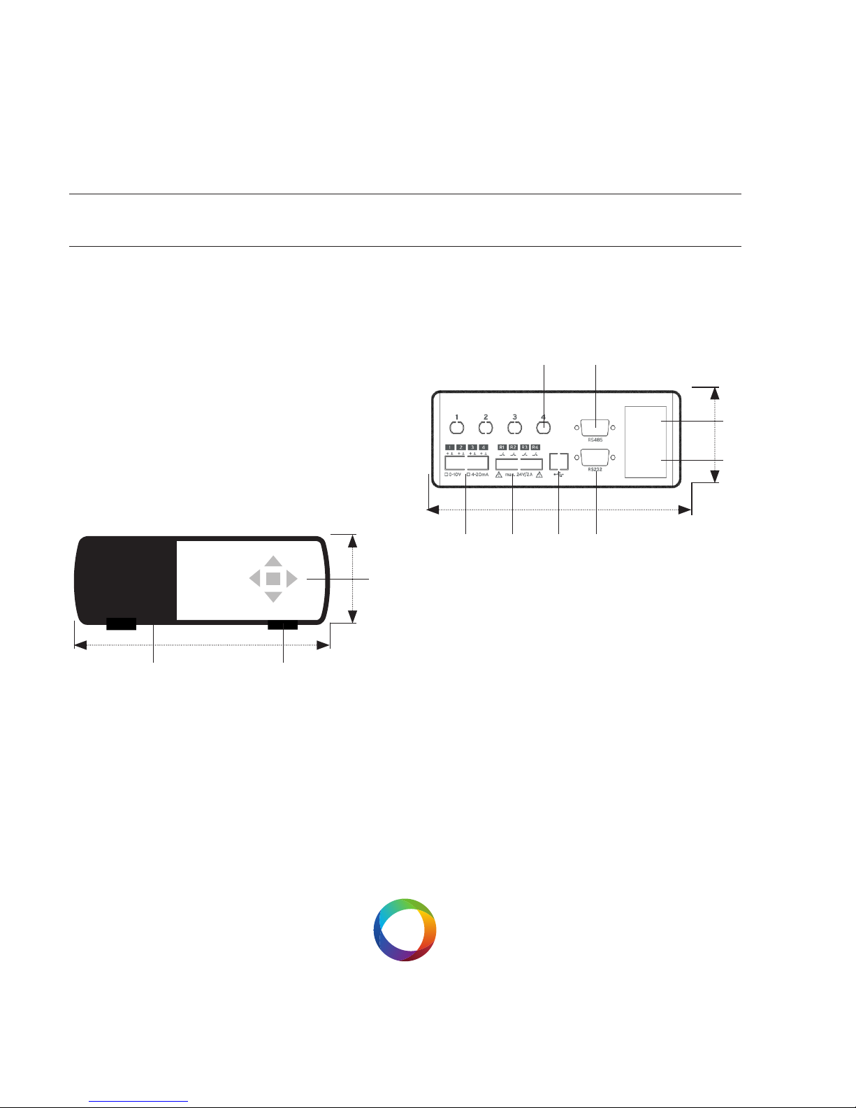
Front panel
The following gure shows the thermometer
front panel:
The following presents an easy overview and
description of the user interfaces and instruc-
tions on how to use the thermometer.
Back panel
The following gure shows the thermometer
back panel:
1) Keypad
For FOTEMP usage a 5 piece keypad is available.
All functions, such as relay settings, one-point
calibration can be performed both via the key-
pads and using the software„Fotemp-Assistent“.
The middle key gives access to the system
menus. To navigate in the menu use the keys
LI and RE
205 MM
81 MM
1
2
3
205 MM
81 MM
45
6
7
891011
Table of contents


