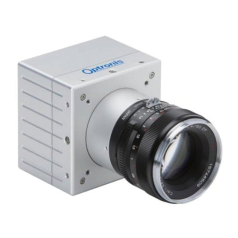
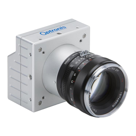
Optronis CP70-004-M/C-19000 User manual

Optronis CoaXPress Cameras
CamPerform CP70 Series
User Manual
CP70-004-M/C-19000
Document Reference
1876-SU-01-E
Release Date
17/08/2018

-2-
About this manual
Thank you for using an Optronis product.
The purpose of this document is to provide a description of Optronis CP70-004-M/C-19000 camera.
Please read this manual thoroughly before operating your new camera for the first time. Please follow all
instructions and observe warnings.
This document is subject to change without notice and corresponds to the last camera firmware version.
You can check product page download area to be sure you are using:
•Last Datasheet version
•Last Manual version
•Last Firmware version
•Last Firmware Update software version
•Last CAD data version
https://optronis.com/en/products/camperform-cp70-004-mc-19000/
Support
We hope that this manual can answer your questions, but should you have any further questions or if you
wish to claim a service or warranty case, please contact your local dealer or refer to the Optronis support.
You can contact our support by using our website or by email at the following address:
support@optronis.com . To process your request efficiently please prepare following information:
•Camera Model name: CPX0-XX-M/C-XX. (See label at the bottom side of the camera).
•Serial-Number: 1xxx-ST-XXX. (See label at the bottom side of the camera).
•Frame Grabber Model
•Cable type (BNC or Din 1.0/2.3, adapter types…)
•Operating System (Windows 7/10/32bit/64bit …)
•Short description of the problem
Contacts
To contact us, please use the information below.
Address
OPTRONIS GMBH
Ludwigstr. 2
D-77694 Kehl
Germany
Tel.: +49 (0) 78 51/91 26-0 / Fax: +49 (0) 78 51/91 26-10
Website
http://optronis.com/en/
Contact Form
http://optronis.com/en/kontakt/
General Inquiries
info@optronis.com
Sales
sales@optronis.com
Support
support@optronis.com

-3-
Table of Contents
1General............................................................................................................................................................ 6
1.1 Declaration of Conformity.......................................................................................................................6
1.2 RoHS Compliance ....................................................................................................................................7
1.3 Standards ................................................................................................................................................7
1.4 Remarks...................................................................................................................................................7
1.5 Scope of Delivery.....................................................................................................................................7
2Getting Started................................................................................................................................................ 8
2.1 General Precautions................................................................................................................................8
2.1.1 Environmental Conditions .................................................................................................................8
2.1.2 Camera Handling................................................................................................................................8
2.2 Setting Up System ...................................................................................................................................9
2.2.1 Typical System Configuration ............................................................................................................ 9
2.2.2 Set Up Lenses.....................................................................................................................................9
2.2.3 Optical Considerations.....................................................................................................................10
3Camera Overview .......................................................................................................................................... 11
3.1 Model Description.................................................................................................................................11
3.1.1 Model Name and Options................................................................................................................11
3.2 Technical Data.......................................................................................................................................12
3.2.1 General Info .....................................................................................................................................12
3.2.2 Spectral Response............................................................................................................................13
3.2.3 Glass Filter........................................................................................................................................14
3.2.4 Mechanical Drawings - Dimensions and Mounting Points ..............................................................15
4Camera Main Features.................................................................................................................................. 16
4.1 Frame Format........................................................................................................................................16
4.1.1 Supported Pixel Formats..................................................................................................................16
4.1.2 Single ROI.........................................................................................................................................16
4.2 Available CXP Configurations ................................................................................................................18
4.3 Acquisition Control - Frame Generation and Synchronization ............................................................. 18
4.4 Frame Rate and Exposure .....................................................................................................................19
4.4.1 Synchronization timings...................................................................................................................20
4.4.2 Max & Min FPS.................................................................................................................................21
4.4.3 Max & Min Exposure Time...............................................................................................................21
4.5 Sync Out Output....................................................................................................................................21
4.6 Image Enhancement .............................................................................................................................22
-4-
4.6.1 Gain..................................................................................................................................................22
4.7 Counter Information .............................................................................................................................22
4.8 Save User Configuration to Flash ..........................................................................................................23
5Camera Hardware Interface.......................................................................................................................... 24
5.1 Connectors and LED ..............................................................................................................................24
5.1.1 Identify Connectors and LED Positions ............................................................................................ 24
5.1.2 Powering Camera.............................................................................................................................24
5.1.3 CoaXPress Connectors .....................................................................................................................25
5.1.4 Auxiliary Connector..........................................................................................................................26
5.1.5 CoaXPress Status LEDs .....................................................................................................................28
6Camera Control Interface.............................................................................................................................. 29
6.1 GenICam XML Interface ........................................................................................................................29
6.1.1 CoaXPress GenICam Compliant Interface........................................................................................29
6.1.2 XML Entry Access Mode...................................................................................................................29
6.1.3 XML Entry Types Description........................................................................................................... 29
6.1.4 XML Entry Allowed Values...............................................................................................................29
6.1.5 XML Masked Values.........................................................................................................................30
6.1.6 Acquisition/Live Stop Required........................................................................................................30
6.2 XML Main Entries - Features Description..............................................................................................31
7Firmware Update .......................................................................................................................................... 34
8Revisions........................................................................................................................................................ 35
8.1 Manual Revision....................................................................................................................................35
8.2 Firmware Revision.................................................................................................................................35

-5-
Table of Figures
Figure 1: Typical System .......................................................................................................................................9
Figure 2: Field of View ........................................................................................................................................10
Figure 3: Camera Model Name Decoder ............................................................................................................11
Figure 4: Camera Serial Number Decoder..........................................................................................................11
Figure 5: Camera Spectral Response (monochrome) .........................................................................................13
Figure 6: Camera Spectral Response (color).......................................................................................................13
Figure 7: Glass Filter typical transmittance (1830-SS-10 IR Filter)......................................................................14
Figure 8: CP70 Dimensions (with F-Mount option) ............................................................................................15
Figure 9: Camera Single ROI control ...................................................................................................................17
Figure 10: Sync Timings ......................................................................................................................................20
Figure 11: CP70 HW Identification......................................................................................................................24
Figure 12: CP70 Power Connector......................................................................................................................25
Figure 13: CP70 Auxiliary Connector ..................................................................................................................26
Figure 14: Sync In Input Schematics ...................................................................................................................27
Figure 15: Sync Out Output Schematics .............................................................................................................27
Figure 16: Camera Series Selection ....................................................................................................................34
Figure 17: Software Interface .............................................................................................................................34

-6-
1General
1.1 Declaration of Conformity

-7-
1.2 RoHS Compliance
CamPerform CP70-004-M/C-19000 cameras are Pb free manufactured.
1.3 Standards
The camera has been developed according to following standards:
•CoaXPress Standard Version 1.1.1 - JIIA CXP-001-2015
•GenICam SFNC 2.3
•GenICam PFNC 2.1
1.4 Remarks
The following signs are used in this user manual to highlight some information:
Remarks and additional information.
Attention, warnings.
1.5 Scope of Delivery
The camera is delivered together with:
•Brief Introduction
Available accessories are:
•Lens mount:
C-Mount lens adapter
F-Mount lens adapter
G-Mount lens adapter
M42x1 lens adapter
M42x0.75 lens adapter
Custom mounts on request
•Pigtail cable CP70, CP90
•Power supply CP70, CP90
•Programming cable CP70, CP90

-8-
2Getting Started
2.1 General Precautions
2.1.1 Environmental Conditions
Recommended environmental conditions are:
Temperature range during operation:
< + 40°C / ~ + 104°F (ambient temperature)
> 0°C / ~ + 32°F (ambient temperature)
Humidity:
< 80%
Optronis does not guaranty camera operation beyond above conditions and camera
lifetime might be reduced.
2.1.2 Camera Handling
Please be careful when using camera. Pay attention especially to:
Camera power
Please be careful when powering camera. Use power over
Coaxpress (PoCXP) or delivered external power supply (option).
Temperature and Humidity
Please respect recommended conditions. You may use controlled
airflow or heatsinks to keep camera in better temperature
conditions.
Direct sun light
Please avoid direct-sun light, camera sensor may be damaged.
Dust and Cleaning
The camera is produced in a dust-controlled environment. Please
be careful when changing lens, mount or accessing any part close
to the sensor.
Always unplug the camera before cleaning it. Do not use cleaning
liquids or sprays. Instead, use a dry and soft duster.
Do not open the housing of the camera.
Warranty becomes void if the camera housing is opened.

-9-
2.2 Setting Up System
2.2.1 Typical System Configuration
A typical system with Optronis CoaXPress camera is composed of:
•An Optronis CoaXPress camera
•CoaXPress cables
•An acquisition and control system (a CoaXPress Frame Grabber in a PC)
•A Control Software based on Frame Grabber features
•Optional features (External power supply, External synchronization system, etc…).
Here is an illustration of such a system:
Figure 1: Typical System
2.2.2 Set Up Lenses
Please be careful when installing or removing camera lens. Depending on your lens mount type and lens, pay
attention to following points:
•If your lens has a mounting mark, first align lens-holder and lens mounting marks and then rotate
anti-clockwise to lock the lens. To remove the lens, unlock the lens-holder silver clip and rotate
clockwise until marks are aligned. Then remove the lens.
•If your lens has a screw thread, rotate anti-clockwise to remove it and clockwise to installing it.
•If you are removing the lens from the camera, always use a cap on the camera to avoid dust
infiltration.
Use also caps on both lens sides for the same reason.
•Do not forget to remove the cap of your lens before using the camera.

-10-
2.2.3 Optical Considerations
A typical optical system can be represented as below.
Figure 2: Field of View
Using above notations:
The sensor size depends on frame dimension:
To select a lens, you can use the following formula:
(distancesinmillimeters)
Alternatively, if you already have a lens, you can compute working distance using the following formula:
(distancesinmillimeters)
Examples:
•PixelSize = 0.008mm
•Full resolution 1696 x 1708
•FoW = Object size = 100 mm
•WD = 300 mm
Selected focal length = 50 mm.
Same example but using a 35mm lens.
Object must be set at least at WD = 217 mm.

-11-
3Camera Overview
3.1 Model Description
3.1.1 Model Name and Options
CamPerform camera series decoding information are illustrated here after. Check camera label on the
bottom side to get both:
•Ref.:
Camera Model Name (see Figure 3)
•S/N.:
Camera Serial Number (see Figure 4)
Figure 3: Camera Model Name Decoder
Figure 4: Camera Serial Number Decoder

-12-
3.2 Technical Data
3.2.1 General Info
Feature
Comments
Power Source
External power supply or Power over CoaXPress (PoCXP):
+ 24V +/- 5% DC
< 200mV ripple
Sensor resolution
192 x 192
Frame rate @ max. sensor res
19789 fps
Image sensor
LUX1310 Global Shutter CMOS
Exposure Time
2 µs - 1/Framerate
Active Area
1.27 mm x 1.27 mm
Sensor Diagonal Dimension
1.8 mm
Pixel Size
6.6 µm
A/D Conversion
12Bit, 8 Bit
Dynamic
TBD dB
Sensitivity
25 V/lux*s @525 nm
Saturation capacity (FWC)
17000 e-
SNR
45 dB
DSNU1288
57.5 e-
PRNU1288
1.27%
Non-linearity error
< 0.5% (calibrated <0.2%)
Shutter efficiency
global electronic shutter
Trigger signal
TTL, 3.3 - 5 V, 10 mA, optically isolated
Trigger modes
internal free-run, external, CXP
Video Interface
CoaxPress
CXP6 –4 or 2 links
Uplink
Over CoaxPress
Mounting Screws
4 x M4 (depth 6mm) in front
4 x M2.5 (depth 5mm) at camera rear
2 x M4 (depth 6mm) on each 4 sides (8 in total)
1 x ¼ - 20 UNC (depth 6mm) on center of each 4 sides (4 in total)
Power consumption
Approximately 8.5 Watt
CoaXPress connectors
CoaxPress 4 x 1.0/2.3 DIN
Size
85 mm x 85 mm x 49 (without mount)
Weight
Approximately 400g without lens and mount

-13-
3.2.2 Spectral Response
Figure 5: Camera Spectral Response (monochrome)
Figure 6: Camera Spectral Response (color)

-15-
3.2.4 Mechanical Drawings - Dimensions and Mounting Points
CP70 Mechanical Dimensions (with F-Mount - /FM option)
Figure 8: CP70 Dimensions (with F-Mount option)

-16-
4Camera Main Features
This paragraph describes camera main features and how they can be used. It focuses on principles and
overall understanding of these features. The camera control interface and specific values used to access
these features are detailed in later paragraph”6.2. XML Main Entries - Features Description, page 31”.
As explained later, these features are controlled by an XML file divided in “entries”. XML entries are using this
special text font for better identification in this paragraph.
Please check also”6.2. XML Main Entries - Features Description, page 31”paragraph to have a precise
description of allowed values for each entry.
4.1 Frame Format
4.1.1 Supported Pixel Formats
The camera supports the following pixel formats:
•Mono 8
•Bayer GR8 (Color cameras only)
•Mono 12
•Bayer GR12 (Color cameras only)
Pixel format is controlled by XML entry:
•PixelFormat
4.1.2 Single ROI
The full frame resolution of the camera is:
•192 x 192
The resolution can be reduced in both directions. Resolution is controlled by XML entries:
•Width / WidthMax
•Height / HeightMax
When reducing the resolution, the ROI is centered in both directions by default. ROI position is controlled by
XML entries:
•OffsetX
•OffsetY

-17-
Figure 9: Camera Single ROI control

-18-
4.2 Available CXP Configurations
The CoaXPress standard allows a lot of different configurations (number of cables, transfer rates, …). You may
want to change it to fit your system needs.
This camera is compatible with:
•CXP6_X2 = 2 links at 6Gbbps
•CXP6_X4 = 4 links at 6Gbbps (default configuration)
CXP configuration is controlled by XML entry:
•ConnectionConfig
Using a lower transfer rate allows longer cable length.
4.3 Acquisition Control - Frame Generation and Synchronization
The camera frame acquisition is controlled by using camera XML AcquisitionStart and AcquisitionStop
commands.
The camera frame acquisition can be synchronized by 3 different ways:
•Camera Internal Generator: (AcquisitionMode = “Continuous”)
In this mode, the camera uses its own sync generator and generates frames continuously when
acquisition is started. Frames are generated according to AcquisitionFrameRate value.
Please check next paragraph “4.4. Frame Rate and Exposure, page 19”for more information about
frame rate and exposure control.
•External Synchronization Generator: (AcquisitionMode = “Single Frame”)
In this mode, the camera uses an external signal to generate frames. You must apply a TTL signal the
Sync In input of the camera. Please respect signal limits (current and voltage) and use the Aux. to
BNC adapter or respect Aux. connector pinout (Hardware information in “5.1.4. Auxiliary Connector,
page 26”paragraph).
Please check next paragraph “4.4. Frame Rate and Exposure, page 19”for more information about
frame rate and exposure control.
•Synchronization over CoaXPress by Frame Grabber: (AcquisitionMode = “CoaxPress”)
CoaXPress standard allows Frame Grabber synchronizing camera frame generation using specific
packets called trigger packets sent on “CoaXPress uplink”.
The frame grabber sends 2 kind of trigger packets: rising edge and falling edge trigger packets. It
allows the camera to build a square synchronization signal:
oIts period is the period of the rising edge trigger packets.
oIts pulse width is the time difference between falling edge trigger packets and rising edge
trigger packets.
So, it is very similar as using an external generator but controlled by user acquisition system (usually
a PC + a CoaXPress frame grabber).
Please check next paragraph “4.4. Frame Rate and Exposure, page 19”for more information about
frame rate and exposure control.
Please check your Frame Grabber manual to use its trigger over CoaXPress mode.

-19-
Acquisition is controlled by XML entries:
•AcquisitionStart
•AcquisitionStop
•AcquisitionMode
4.4 Frame Rate and Exposure
•Camera Internal generator: (AcquisitionMode = “Continuous”)
Frame rate: In this mode, frame rate is defined by camera register and can be modified using camera
XML control interface.
Exposure: In this mode, the exposure is defined by camera register and can be modified using
camera XML control interface.
•External Synchronization generator: (AcquisitionMode = “Single Frame”)
Frame rate: In this mode, the frame rate is defined by the external TTL signal period. The allowed
frame rate range is the same as in Internal Synchronization.
Exposure: In this mode, the exposure can be controlled by 2 different sources. The XML “Granularity”
feature allows you to select the control source:
oGranularity = “On”: Same as in the “Continuous” mode, camera register controls the
exposure and can be modified using camera XML control interface.
oGranularity = “Off”: The exposure is controlled by the external TTL signal pulse width.
•Synchronization over CoaXPress by Frame Grabber: (AcquisitionMode = “CoaxPress”)
Frame rate: In this mode, the frame rate is defined by Frame Grabber “Trigger packets” period. The
allowed frame rate range is the same as in Internal Synchronization.
Exposure: In this mode, the exposure can be controlled by 2 different sources. The XML Granularity
feature allows you to select the control source:
oGranularity = “On”: Same as in the “Continuous” mode, camera register controls the
exposure and can be modified using camera XML control interface.
oGranularity = “Off”: The exposure is controlled by the CoaXPress TTL signal pulse width.
Frame rate and exposure are controlled by XML entries:
•AcquisitionFrameRate
•ExposureTime
•Granularity

-20-
4.4.1 Synchronization timings
Figure 10: Sync Timings
@ Internal Synchronization
Timings are controlled by camera. Using XML interface range ensures that timings are respected.
@ External Synchronization
•If Granularity is enabled (“On”):
oT2 is controlled by user external generator signal period
oT1 is controlled by camera
•If Granularity is disabled (“Off”):
oT2 is controlled by user external generator signal period
oT1 is controlled by user external generator pulse width
In both cases, timings must be respected.
@Synchronization over CoaXPress
•If Granularity is enabled (“On”):
oT2 is controlled by CoaXPress frame grabber “signal” period
oT1 is controlled by camera
•If Granularity is disabled (“Off”):
oT2 is controlled by CoaXPress frame grabber “signal” period
oT1 is controlled by CoaXPress frame grabber “signal” pulse width
In both cases, timings must be respected.
Table of contents
Other Optronis Digital Camera manuals

Optronis
Optronis CP80-4-M/C-500 User manual

Optronis
Optronis CamPerform CP80-25-M User manual

Optronis
Optronis CamPerform CoaxPress CP70-1-M-1000 User manual

Optronis
Optronis CP80-3-M/C-540 User manual

Optronis
Optronis CR450x2 User manual

Optronis
Optronis CP70-12-M/C-188 User manual

Optronis
Optronis CP70-16-M/C-148 User manual

Optronis
Optronis CR-S3500 User manual

Optronis
Optronis CamRecord CR Series User manual

Optronis
Optronis CamRecord CL4000CXP User manual